manuals.online logo
Brands
  1. Home
  2. •
  3. Brands
  4. •
  5. ZigBoat
  6. •
  7. Accessories
  8. •
  9. ZigBoat ZB203 User manual

ZigBoat ZB203 User manual

eng
Precautions
• Do not remove the product label as it
contains important information.
• Do not paint the alarm.
min 30 cm
max 50 cm
wall
ceiling
min 50 cm wall
ceiling
Green dot: The sensor is working properly
Red dot: The sensor is not able to reach the
Gateway.
• Please check the battery status;
• Please check that the correct serial number
has been entered
• In case of a weak or a bad signal, change the
location of the ZigBoat™ Heat Alarm Sensor
“OK”: No rapid heat rise detected
“ALARM”: The sensor detects rapid heat rise
or absolute heat levels and will send push
notications if the gateway is connected to
internet.
Mounting
1. Detach the sensor from the mounting base
by twisting counter-clockwise.
2. Use the mounting base ring to mark the
screw holes on the ceiling or on the wall.
WALL PLACEMENT
The Heat Alarm Sensor should be placed
between 30 cm (12”) and 50 cm (20”) from the
ceiling.
CEILING PLACEMENT
The Heat Alarm Sensor should be a minimum
of 50 cm (20’’) from the wall.
Placement
• Place the alarm indoors at a temperature
between 0-50°C (32-122°F).
• The distance between the Heat Alarm
Sensor and walls, ventilation or other
obstacles, should be at least 50 cm (20”).
• Place the Heat Alarm Sensor at least 4
meters (12’) from a replace or stove.
• Place the Heat Alarm Sensorwithin reach for
battery testing and maintenance.
2. To nd the serial number detach the sensor
mount base.
Product description
The sensor is measuring sudden rises of
ambient temperatures. The heat alarm sensor
can be installed where smoke or fumes are
normally present where a normal smoke
detector would give false alarms.
The Heat Alarm Sensor is specically useful
in environments where a traditional optical
smoke sensor can cause false detections. The
Heat Alarm Sensor is designed for installation
in places with risk for smoky, dusty, or humid
environments.
OWNER MANUAL
Heat Alarm Sensor
Version 1.0
3. You can change the devices name by
selecting “Name” (g. 4). Then, press the
button “Add Device”.
4. Insert the battery (1xCR123) noting the
polarity.
5. The Heat Alarm Sensor will now start
searching (up to 15 minutes) for the ZigBoat™
network to join.
6. While searching for the ZigBoat™ network to
join, the LED ashes red.
7. When the LED stops ashing, the Heat
Alarm has successfully joined the ZigBoat™
network.
To check the correct conguration, select the
overview tab of the ZigBoat™ App. (g. 5)
3. Use enclosed screws and plugs to install
the mounting base on the marked position.
4. Attach the sensor by twisting clockwise
until it clicks. If the battery is missing or
inserted incorrectly, it will be impossible to
click the alarm in the mounting base.
code: ZB203
Adding the sensor to the Gateway
NOTE: Make sure Gateway is turned on and
congured correctly for more details see the
Gateway owner manual.
1. Open the ZigBoat™ App, select the Gateway
in the ZB Gateways menu, waiting a few
seconds. then select the menu button on
the top right (g. 1) Select “Device list” (g.
2). Add the sensor by entering the serial
number which is on the sensor’s label (g. 3).
Fig. 1Fig. 2
Fig. 3
Fig. 4
CR123A
PRODUCT
LABEL
Fig. 5
RECOMMENDED LOCATIONS:
• Galley
• Bathroom
NOTE: It is not suggested to use it in engine
rooms
OK
Heat Sensor
Kitchen #1
• Salon
• Cabin
Glomex assumes no responsibility for any
errors, which may appear in this manual.
Furthermore, Glomex reserves the right to alter
the hardware, software, and/or specications
detailed herein at any time without notice, and
All rights reserved.
Distributed by Glomex Srl
via Faentina 165/G
48124 Ravenna
Italy
Other certications
• ZigBee® certied
IN ACCORDANCE WITH THE DIRECTIVES
• Radio Equipment Directive 2014/53/EU
• EMC Directive 2014/30/EU
• RoHS Directive 2011/65/EU
CE certication
The CE mark axed to this product conrms
its compliance with the European Directives
which apply to the product and, in particular,
its compliance with the harmonized standards
and specications.
Disposal
Dispose the product and battery properly at the
end of life. This is electronic waste which should
be recycled.
Battery replacement
CAUTION: When removing cover for battery
change - Electrostatic Discharge (ESD) can
harm electronic components inside
1. To replace the battery, remove the Heat
Alarm Sensor from the mounting base by
twisting counter-clockwise.
CAUTION: RISK OF EXPLOSION IF BATTERIES
ARE REPLACED BY AN INCORRECT TYPE.
DISPOSE OF THE BATTERIES IN ACCORD-
ANCE WITH INSTRUCTIONS.
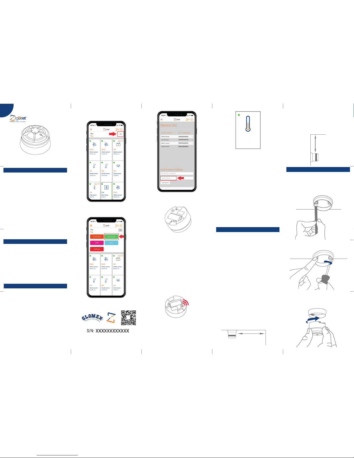
Resetting
Resetting is needed if you want to connect
your Heat Alarm Sensor to another gateway
or if you need to perform a factory reset to
eliminate abnormal behavior.
STEPS FOR RESETTING
1. Remove the sensor from the mounting base
by twisting it counter-clockwise.
2. Press and hold the LED button until it ashes
continuously.
3. Release the button.
4. The resetting process is complete when
the LED starts to ash.
Modes
SEARCHING GATEWAY MODE
Red LED light in the back of the device is
ashing every second (up to 15 minutes).
NORMAL MODE
Front LED is ashing every 45 seconds, means
Fault nding
• If the Heat Alarm Sensor does not work
when the test button is pushed, the
probable cause is a faulty battery. Replace
the battery if it is worn out.
• If the search for a gateway has timed out, a
short press on the LED button will restart it.
that the battery should be replaced.
ALARM MODE
The simultaneous ashing of the front red LED
and sounding of intermittent audible signal.
When heat is detected, the alarm will
sound, press the “button/top” of the Sensor
to acknowledge and stop the siren. After
silencing the alarm, no other alerts will be
detected for 10 minutes allowing for time to
address any issues.
LOW BATTERY MODE
Simultaneous audible signals and front LED
ashes every 45 seconds, means that the
battery should be replaced.
REPLACE DEVICE MODE
If there are no simultaneous audible signals
and the front LED ashes every 45 seconds,
this means that the device should be replaced.
The life expectancy of heat alarm sensors
is generally 10 years, after which point their
sensors begin to lose sensitivity.
Consulta il manuale utente in italiano su:
Consultez le manuel d’utilisation en français
sur:
Siehe das deutsche Benutzerhandbuch auf:
Consulte el manual de usuario en español en:
Testing
• Always test the working order of the Heat
Alarm Sensor after installation or battery
change.
• When pressing the Alarm Sensor button, an
alarm sound should be heard.
• A network alarm test can be performed by
holding down the alarm button for at least
6.5 seconds
2. Replace the battery noting the polarity. The
Heat Alarm uses 1xCR123 battery.
3. Attach the Alarm Sensor in the mounting
base by twisting clockwise until it clicks,
and test the Alarm Sensor.
Warranty
Glomex guarantees the Heat Alarm Sensor
(ZB203) against manufacturing defects for a
period of 2 years from date of purchase.
Warranty can be in the form of repair or
replacement of the unit if manufacturing
defects have been found and are conrmed
by Glomex or one of its aliates. In order to
validate warranty, either the original sales
receipt or a copy must be provided at the time
warranty is requested. Before returning any
items for warranty, please contact the Glomex
Customer Service department to receive a
RMA which should be completed and sent with
the unit to the following address:
GLOMEX S.r.l.
Via Faentina 165/G
48124 Ravenna (Italy)
complete with all the accessories supplied at
the time of purchase for shipment. The serial
number must neither be erased nor made
illegible, otherwise the warranty will be voided.
Glomex does not make any commitment to
update the information contained herein. All
the trademarks listed herein are owned by their
respective owners.

Other ZigBoat Accessories manuals

ZigBoat ZB204 User manual

ZigBoat

ZigBoat ZB204 User manual

ZigBoat ZB206 User manual

ZigBoat

ZigBoat ZB206 User manual

ZigBoat Schuko ZB207 User manual

ZigBoat

ZigBoat Schuko ZB207 User manual

Popular Accessories manuals by other brands

Penveu Penveu quick start guide

Penveu

Penveu Penveu quick start guide

Dekko ECA STO-WAY installation guide

Dekko

Dekko ECA STO-WAY installation guide

Zamel sundi CALIPSO ST-980 user manual

Zamel

Zamel sundi CALIPSO ST-980 user manual

Revolabs Tabletop Dialer 07-TTDIAL-01 user guide

Revolabs

Revolabs Tabletop Dialer 07-TTDIAL-01 user guide

Ronde & Schwarz R&S NRP18S Series user manual

Ronde & Schwarz

Ronde & Schwarz R&S NRP18S Series user manual

Crestron B-G1-FPAR datasheet

Crestron

Crestron B-G1-FPAR datasheet

Clas Ohlson SC329D quick start guide

Clas Ohlson

Clas Ohlson SC329D quick start guide

BD Sensors DM01 operating manual

BD Sensors

BD Sensors DM01 operating manual

IFM Electronic Efectror 200 OGE2 Series operating instructions

IFM Electronic

IFM Electronic Efectror 200 OGE2 Series operating instructions

Dometic RTX1000 installation manual

Dometic

Dometic RTX1000 installation manual

IFM Electronic efector150 operating instructions

IFM Electronic

IFM Electronic efector150 operating instructions

Etymotic BlastPLG EB1 user manual

Etymotic

Etymotic BlastPLG EB1 user manual

Intermatic HA04 supplementary guide

Intermatic

Intermatic HA04 supplementary guide

IFM Electronic efector 300 SU7000 operating instructions

IFM Electronic

IFM Electronic efector 300 SU7000 operating instructions

Sigma UV Sanitizing Wand quick start guide

Sigma

Sigma UV Sanitizing Wand quick start guide

Colugo Bug Net instructions

Colugo

Colugo Bug Net instructions

Keysight Technologies U2040 X-Series Programming guide

Keysight Technologies

Keysight Technologies U2040 X-Series Programming guide

Philips CRP382 brochure

Philips

Philips CRP382 brochure

manuals.online logo
manuals.online logoBrands
  • About & Mission
  • Contact us
  • Privacy Policy
  • Terms and Conditions

Copyright 2025 Manuals.Online. All Rights Reserved.