INSTALLATION AND OPERATING INSTRUCTIONS: Pneumatic gripper, GPP/GPD5000 series
Installation and
operating instructions
GPP/GPD5000 series
DDOC00196
Index g
EN / 8/13/2019
Im Salmenkopf
77866 Rheinau,
Germany
+49 7844 9138 0
+49 7844 9138 80
www.zimmer-group.de
Zimmer GmbH ●Im Salmenkopf 5 ●77866 Rheinau, Germany ●+49 (0) 7844 9138 80 ● +49 7844 9138 80 ●www.zimmer-group.com
6.3 Power supply installation
Power supply bp is located laterally on the housing.
ÖThe exact positions are referenced in the technical data sheet, which you can view online at www.
zimmer-group.com.
ÖRefer to the technical data sheet for alternative power supply positions!
NOTICE:
Close o the unused pneumatic connections with dummy plugs.
Use compressed air in accordance with DIN ISO 8573-1 [4:4:4].
6.4 Installation of accessories
INFORMATION:
If any accessories not marketed or authorized by Zimmer GmbH are used, the function of the gripper cannot be
guaranteed.
The accessories from Zimmer GmbH are specically tted for the individual grippers.
Corresponding optional accessories and those included in the scope of supply can be found at www.zim-
mer-group.com.
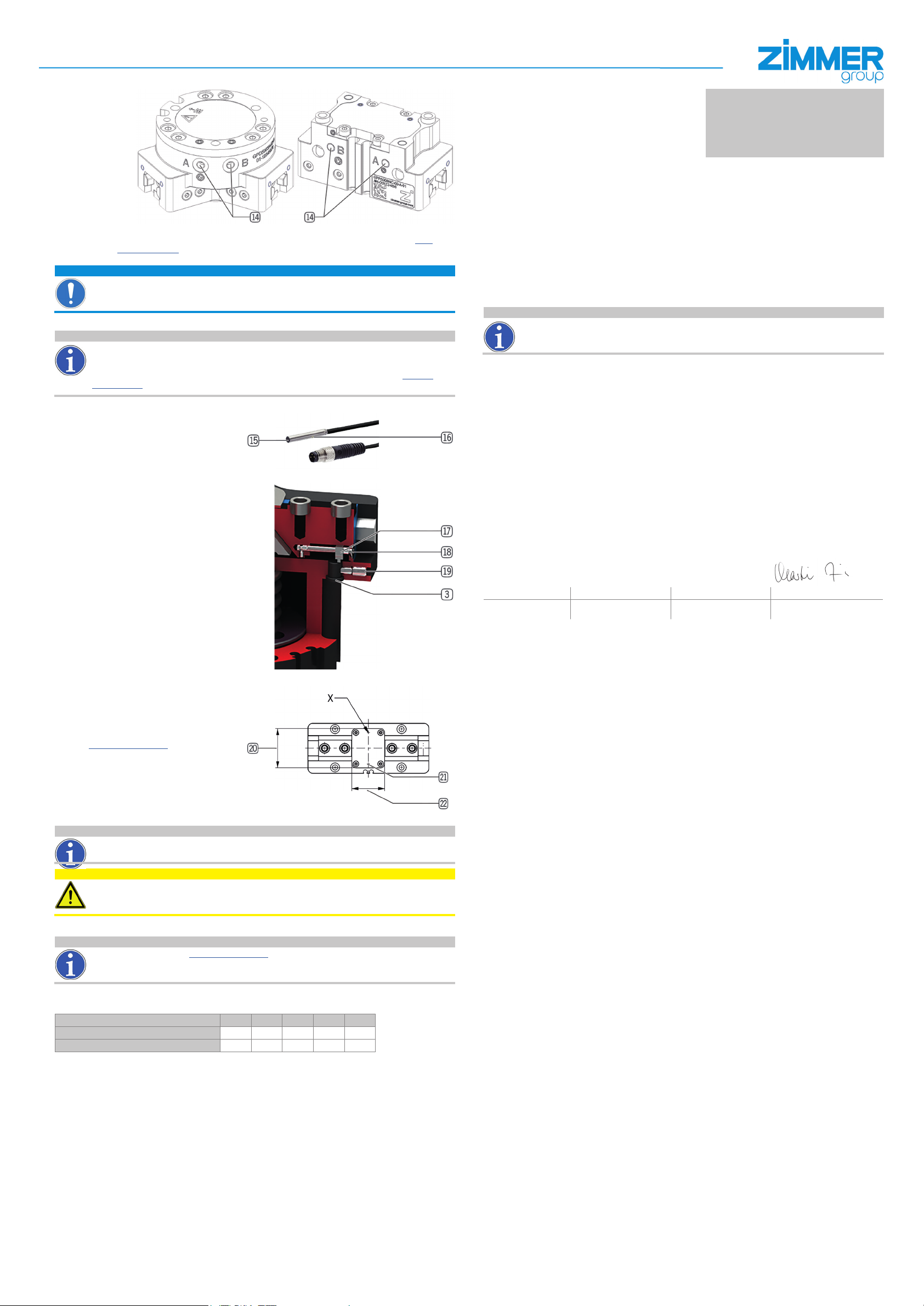
6.6 Installing and adjusting inductive proximity switches
Using the inductive proximity switches, any
desired position of the gripper ngers can be
detected directly at the mechanical system.
Inductive proximity switches can be used in
ascending order starting from sizes GPP/GPD
5006!
The following variants are excluded:
GPP/GPD50-AL-A
The following work steps must be observed when
installing/adjusting inductive proximity switches:
► Insert the inductive proximity switch bq in
designated mounting block 3.
►Slide in as far as it will go and secure with
clamping screw bu.
► Connect the inductive proximity switch bq to
the operating voltage (10 - 30 V DC).
►Bring the gripper jaws into the desired grip-
ping position.
►Adjust the cam switch bs using the setscrew
bt until the function display br illuminates on
the inductive proximity switch.
► The inductive proximity switch bq is ready for
operation.
6.7 Installingacustomer-specicsupport
structure
It is possible to remove the cover plate cm
installed by the manufacturer in order to use a
customer-specic support structure.
The dimensions required for the customer-spe-
cic support structure are referenced in the
technical data sheet found on our website at
Öwww.zimmer-group.com
The dimension cn must under no circum-
stances be exceeded by the customer-specic
support structure. The support structure must
be designed such that it does not impede the
movement of the gripper jaws.
The dimension cl may be exceeded by the
customer-specic support structure.
There are additional blind holes with ts for a customer-specic connection below the cover plate cm.
INFORMATION:
Make sure to observe the following for GPD5000 series grippers:
If the gripper has been mounted using a pressure piece, no additional support structure can be incorporated.
CAUTION:
Non-compliance may result in injuries!
The customer-specic support structure must not collide with other parts of the machine in which the gripper is
installed while the gripper is moving.
7 Technical data
INFORMATION:
Please refer to our website Öwww.zimmer-group.com for technical data.
This data varies within the series depending on the specic design. If you should have further questions about
products or technical data, please contact Zimmer GmbH Customer Service.
8 Maintenance
Maintenance-free operation of the dierent gripper variants is ensured within the following parameters.
Cycles Variant AL 00 20 21 24
15 million maintenance-free cycles (max.) X
30 million maintenance-free cycles (max.) XXXX
The maintenance interval may shorten under the following circumstances:
• Operation with compressed air that does not comply with DIN ISO 8573-1 [4:4:4].
• Dirty environment.
• Improper use and use that does not comply with the power specications.
• Ambient temperature of above 60 °C
Even though the gripper is, as mentioned, maintenance-free, perform a regular visual inspection to check for any damage
or contamination.
We recommend using Zimmer Customer Service for maintenance.
Dismantling and reassembling the gripper without authorization may result in complications, as special installation equip-
ment is required in some cases.
Zimmer GmbH shall not be liable in the event of unauthorized dismantling and reassembling of the gripper or in the event
of any malfunction or damage resulting from this.
9 Transport/storage/preservation
► The transport and storage of the gripper must take place exclusively in the original packaging.
►If the gripper has already been installed on the higher-level machine unit, it must be ensured during transport that no
uncontrolled movements take place. Before commissioning the machine after transport, check all power and commu-
nication connections as well as all mechanical connections.
► If the product is stored for an extended period, the following points are to be observed:
ÖKeep the storage location as dust-free and dry as possible.
ÖAvoid temperature uctuations/observe and adhere to the temperature range.
ÖAvoid wind/drafts/water condensation formation.
ÖStore product packaged.
ÖDuring storage, it must be kept from direct sunlight.
► Visually inspect all of the components.
►Remove all foreign objects.
►Close pneumatic connections using suitable covers.
10 Decommissioning and disposal
INFORMATION:
If the gripper reaches the end of its operational phase, it can be completely disassembled and disposed of
according to material groups. Disconnect the gripper from the power supply completely. When disposing of it,
observe the locally applicable environmental regulations and codes and regulations for disposal.
11 Declaration of Incorporation
In terms of the EU Machinery Directive 2006/42/EC (Annex II 1 B).
Name and address of the manufacturer:
Zimmer GmbH, Im Salmenkopf 5, 77866 Rheinau, Germany +49 7844 9138 0, +49 7844 9138 80,
www.zimmer-group.com
We hereby declare that the incomplete machine described below
Product designation: Gripper, pneumatic
Type designation: GPP/GPD5 series
satises the following basic requirements of the Machinery Directive 2006/42/EC:
No. 1.1.2., No. 1.1.3., No. 1.1.5., No. 1.3.2., No. 1.3.4., No. 1.3.7., No. 1.5.3., No. 1.5.4., No. 1.5.8., No. 1.6.4., No. 1.7.1., No.
1.7.4
We also declare that the specic technical documents were produced in accordance with Annex VII Part B of this Directive.
We undertake to provide the market supervisory bodies with electronic versions of special documents for the incomplete
machine through our documentation department, should they have reason to request them.
The incomplete machine may only be commissioned if it has been ascertained, if applicable, that the machine or
system in which the incomplete machine is to be installed satises the requirements of Directive 2006/42/EC on
Machinery and an EC Declaration of Conformity has been drawn up in accordance with Annex II 1 A.
Authorized representative for the compilation of
relevant technical documents
Kurt Ross See manufacturer's address Rheinau, Germany, 8/1/2019 Martin Zimmer
First name, last name Address Place and date of issuance (Legally binding signature)
Managing Director


