ZKETECH EBC-A01 User manual

ZKETECH
ReleaseDate2017-01-01
Multifunction Electronic Load
(EBC-A01)

http://www.zketech.com
EBC-A01 User Manual
Copyright (C) 2006-2017 ZKETECH
1. Features
1.1 Battery capacity test
This tester is designed for discharging and capacity tests of a wide range of batteries and
battery banks, like LiPo and LiFe batteries (packs) within 10V, low capacity batteries (packs)
within 30V, dry cells (AAA) and button cell batteries.
1.2 Power performance test
This tester supports performance and aging tests of various kinds of low current DC power
supplies.
2. Specifications
1) Power supply: DC 12V, 2A or above
2) Voltage range: 0-30.00V, stepper 0.01V (maximum voltage is 10V during charging)
3) Current range: 0.001-1A, stepper 0.001A
4) Charging mode:
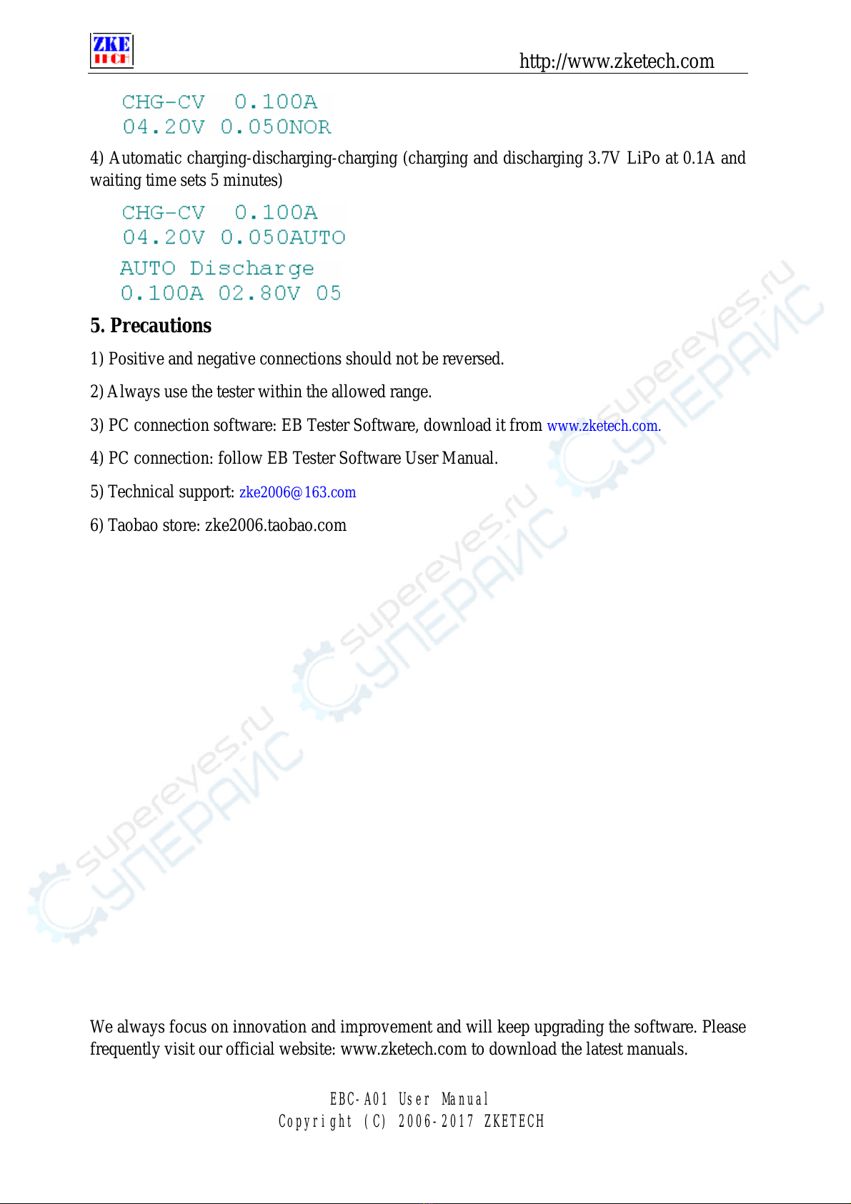
²CHG-CV: charging at a constant current and voltage, applicable only for LiPo and
LiFe)
5) Discharging mode:
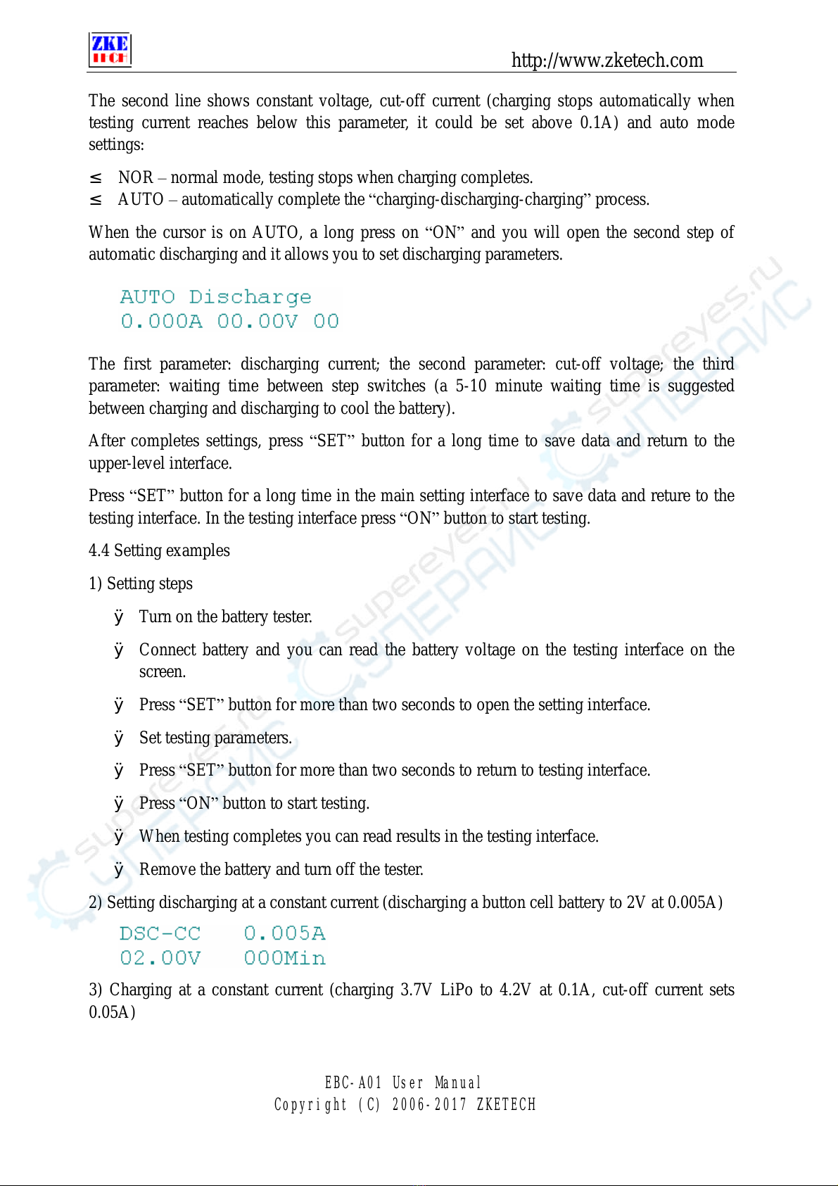
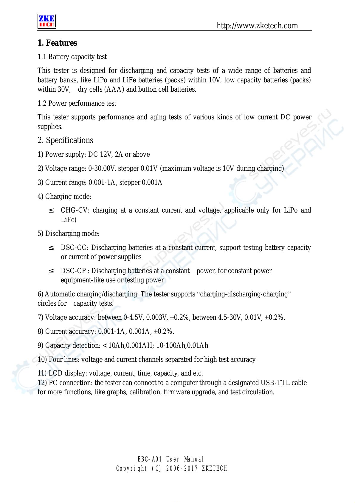
²DSC-CC: Discharging batteries at a constant current, support testing battery capacity
or current of power supplies
²DSC-CP : Discharging batteries at a constant power, for constant power
equipment-like use or testing power
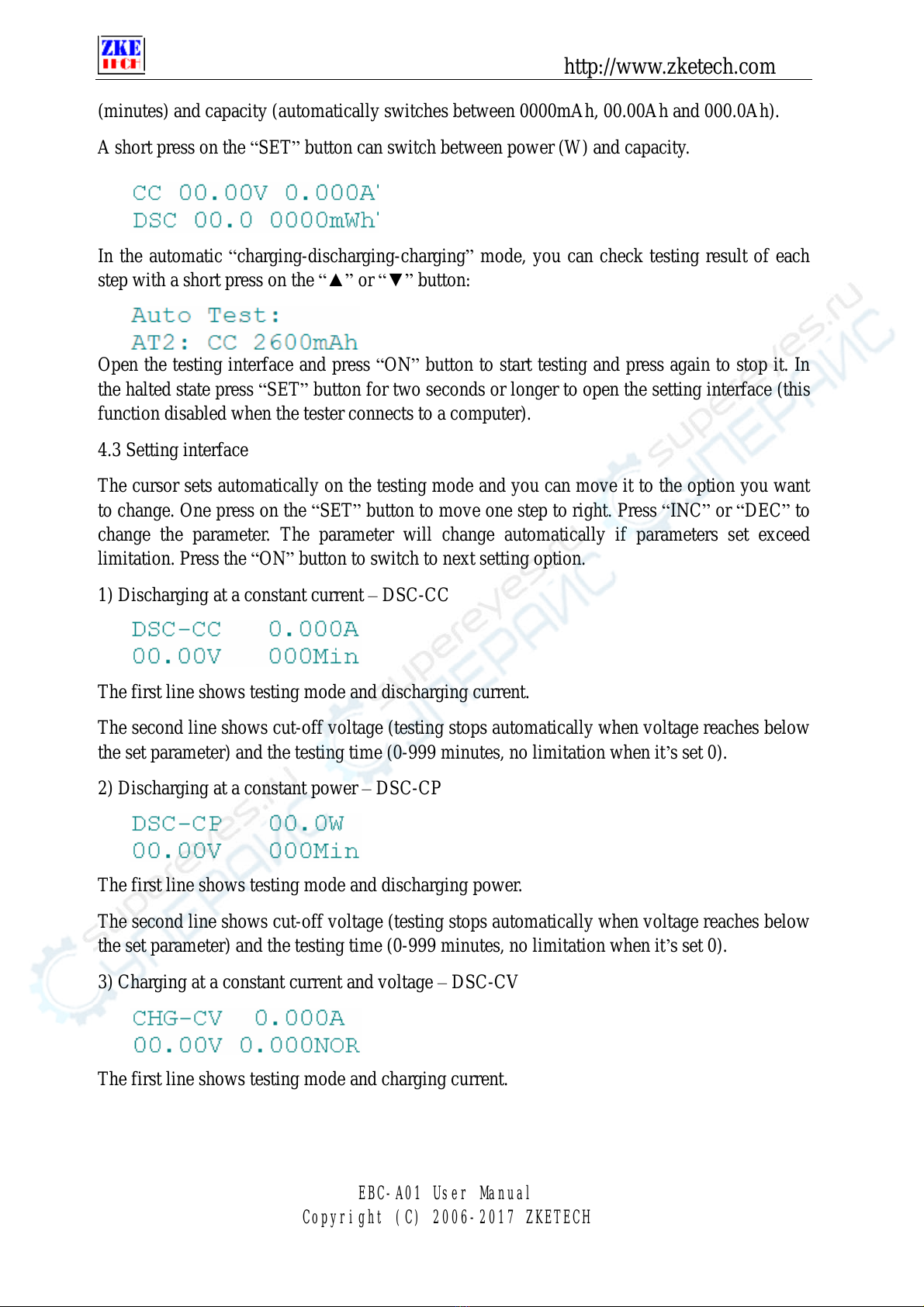
6) Automatic charging/discharging: The tester supports charging-discharging-charging”
circles for capacity tests.
7) Voltage accuracy: between 0-4.5V, 0.003V, ±0.2%, between 4.5-30V, 0.01V, ±0.2%.
8) Current accuracy: 0.001-1A, 0.001A, ±0.2%.
9) Capacity detection: < 10Ah,0.001AH; 10-100Ah,0.01Ah
10) Four lines: voltage and current channels separated for high test accuracy
11) LCD display: voltage, current, time, capacity, and etc.
12) PC connection: the tester can connect to a computer through a designated USB-TTL cable
for more functions, like graphs, calibration, firmware upgrade, and test circulation.

http://www.zketech.com
EBC-A01 User Manual
Copyright (C) 2006-2017 ZKETECH
3. Connecting patterns
3.1 Testing ports
The tester has four banana jacks which connect with A+/V+/V-/A-. A+ and A- ports are
connected with the positive and negative ends of the test objects, working as the current
channel in charging and discharging. V+ and V- ports are connected with the positive and
negative ends of the test objects, working as the voltage channel in voltage tests. This way of
using four individual cables will help eliminate the effect of wires on the test result and
improve the test precision.
3.2 PC connection
The tester can be connected with a computer through a designated USB-TTL cable (with Mini
port).
3.3 Input power:
The tester works on a power supply of DC 12V, 3.5A or above and interface specification of
5.5/2.1 (inside positive and outside negative).
4. Display and setting
4.1 Buttons
ON —start and stop
SET—set up and switch
INC—page up and increase
DEC —page down and decrease
4.2 Testing interface
The first line shows testing mode, voltage and current. Testing modes include:
CC —discharging at a constant current
CP —discharging at a constant power
CV —charging at a constant current and voltage
The second line shows working state (it shows OFF when the tester stops working and it turns
DSC or CHG at working. It reads ATI when you choose automatic
charging-discharging-charging mode, and 1 refers to current working step), working time

http://www.zketech.com
EBC-A01 User Manual
Copyright (C) 2006-2017 ZKETECH
(minutes) and capacity (automatically switches between 0000mAh, 00.00Ah and 000.0Ah).
A short press on the SET”button can switch between power (W) and capacity.
In the automatic charging-discharging-charging”mode, you can check testing result of each
step with a short press on the ▲” or ▼” button:
Open the testing interface and press ON”button to start testing and press again to stop it. In
the halted state press SET”button for two seconds or longer to open the setting interface (this
function disabled when the tester connects to a computer).
4.3 Setting interface
The cursor sets automatically on the testing mode and you can move it to the option you want
to change. One press on the SET”button to move one step to right. Press INC”or DEC”to
change the parameter. The parameter will change automatically if parameters set exceed
limitation. Press the ON”button to switch to next setting option.
1) Discharging at a constant current –DSC-CC
The first line shows testing mode and discharging current.
The second line shows cut-off voltage (testing stops automatically when voltage reaches below
the set parameter) and the testing time (0-999 minutes, no limitation when it’s set 0).
2) Discharging at a constant power –DSC-CP
The first line shows testing mode and discharging power.
The second line shows cut-off voltage (testing stops automatically when voltage reaches below
the set parameter) and the testing time (0-999 minutes, no limitation when it’s set 0).
3) Charging at a constant current and voltage –DSC-CV
The first line shows testing mode and charging current.

http://www.zketech.com
EBC-A01 User Manual
Copyright (C) 2006-2017 ZKETECH
The second line shows constant voltage, cut-off current (charging stops automatically when
testing current reaches below this parameter, it could be set above 0.1A) and auto mode
settings:
²NOR –normal mode, testing stops when charging completes.
²AUTO –automatically complete the charging-discharging-charging”process.
When the cursor is on AUTO, a long press on ON”and you will open the second step of
automatic discharging and it allows you to set discharging parameters.
The first parameter: discharging current; the second parameter: cut-off voltage; the third
parameter: waiting time between step switches (a 5-10 minute waiting time is suggested
between charging and discharging to cool the battery).
After completes settings, press SET”button for a long time to save data and return to the
upper-level interface.
Press SET”button for a long time in the main setting interface to save data and reture to the
testing interface. In the testing interface press ON”button to start testing.
4.4 Setting examples
1) Setting steps
ØTurn on the battery tester.
ØConnect battery and you can read the battery voltage on the testing interface on the
screen.
ØPress SET”button for more than two seconds to open the setting interface.
ØSet testing parameters.
ØPress SET”button for more than two seconds to return to testing interface.
ØPress ON”button to start testing.
ØWhen testing completes you can read results in the testing interface.
ØRemove the battery and turn off the tester.
2) Setting discharging at a constant current (discharging a button cell battery to 2V at 0.005A)
3) Charging at a constant current (charging 3.7V LiPo to 4.2V at 0.1A, cut-off current sets
0.05A)

http://www.zketech.com
EBC-A01 User Manual
Copyright (C) 2006-2017 ZKETECH
4) Automatic charging-discharging-charging (charging and discharging 3.7V LiPo at 0.1A and
waiting time sets 5 minutes)
5. Precautions
1) Positive and negative connections should not be reversed.
2) Always use the tester within the allowed range.
3) PC connection software: EB Tester Software, download it from www.zketech.com.
4) PC connection: follow EB Tester Software User Manual.
5) Technical support: zke2006@163.com
6) Taobao store: zke2006.taobao.com
We always focus on innovation and improvement and will keep upgrading the software. Please
frequently visit our official website: www.zketech.com to download the latest manuals.
Table of contents
Other ZKETECH Test Equipment manuals
Popular Test Equipment manuals by other brands

Reed Instruments
Reed Instruments R2810 instruction manual

PCB Piezotronics
PCB Piezotronics 498A-0016 Installation and operating manual

X-Rite
X-Rite i1Display Pro Plus quick start guide

Bosch
Bosch SCT 815 Unpacking & assembly instructions

RuiDeng
RuiDeng UM34C instructions

Framatome
Framatome HELIOS user manual