manuals.online logo
Brands
  1. Home
  2. •
  3. Brands
  4. •
  5. ZLT
  6. •
  7. IP Phone
  8. •
  9. ZLT X100 PRO User manual

ZLT X100 PRO User manual

ZLT X100 PRO User Manual
V1.0
Thank you for choosing our 5G wireless data terminal products.
In order to enable you to better use the data terminal, please read
this manual carefully, and keep it on standby for future use.
Our company reserves the right to modify the technical
parameters and specifications of this manual, and we will timely
improve the printing errors and discrepancies with the latest data of
this manual. All changes will not be notified in advance, and the
Company reserves the right of final interpretation.
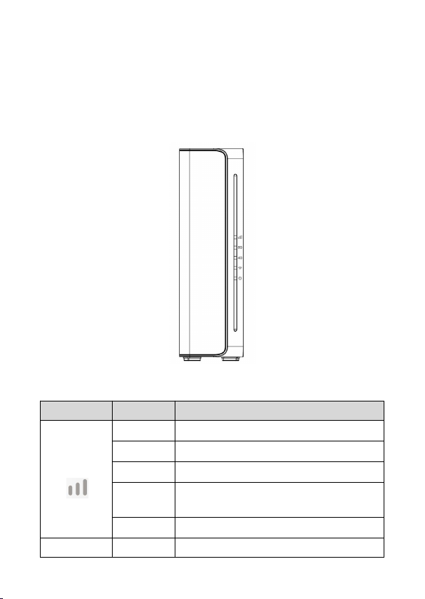
ZLT X100 PRO is a high-performance 5G indoor data terminal,
which supports NR (SA&NSA) and LTE, converts cellular network
data into WiFi and wired network interface data, supports one
gigabit LAN interface, and one telephone interface, and 2.4G+5G
dual band WiFi hotspot (AP). It is applicable to domestic or
commercial scenarios where communication networks and WiFi
hotspots need to be rapidly deployed.
1. Main technical indicators of product
● Wired network port:Support 1000Mbps RJ45 network port
● Power:input : AC 100V~240V, 50Hz~60Hz
output : DC 12V/1.5A
● Operating temperature: 0℃~ +45℃
● Relative humidity: 5%~95%
● Dimensions: L90 x W50 x H163 (mm)
● Weight: about 415g
2. Installation instructions
1) Take out the wireless data terminal and install the SIM card
into the card slot according to the direction marked on the
data terminal.
2) Use a standard RJ45 network cable to connect the LAN port of
the data terminal to the computer.
3) Use the power adapter to connect the external power socket
and the data terminal, and the data terminal will automatically
turn on when power on. After about 1~2 minutes, the data
terminal completes initialization.
4) Place the data terminal on a flat surface.
5) The WiFi function is enabled by default. You can use mobile
phones, tablets and other devices with wireless connection
functions to connect to the data terminal. The default SSID
and WiFi password information for wireless connection can be
obtained from the nameplate at the bottom of the data
terminal.
Attention:
1) Do not install the SIM card with power on.
2) When handling the SIM card, do not touch the metal
contact surface to avoid damage to the card by static
electricity.
3) The operating temperature range of this product is 0~45℃;
please do not operate beyond this temperature range.
4) Please use the adapter specified by this product to prevent
abnormal operation of the machine.
5) This device meets the EU requirements (2014/53/EU
Article 3.1a) on the limitation of exposure of the general
public to electromagnetic fields by way of health
protection. The device complies with RF specifications
when the device is used at 20 cm from your body.
3. About Data Terminal
This data terminal can operate under 4G (LTE) / 5G (NR)
network, allowing you to connect to the Internet through WiFi or
network port.
3.1 Interface Description
Figure 1 Interface Diagram
Interface
Type
Definition
Description
DC
Power
connector
Used to connect the matching power
adapter.
RST
Reset
button
Used to reset the device to factory
settings. working on equipment
In this state: press and hold for 6
seconds, the device will restore the
factory settings.
TYPE-C
Debug
interface
Used for device debug log output.
LAN
LAN port
It is used to connect to the network
port of a computer or other
equipment.
SIM Card
SIM card
interface
Used to insert SIM card.
TEL
Telephone
interface
Connect to the phone for call function
Note: The debugging interface cannot be used for power supply,
please use the factory matching power adapter for power
supply.
3.2 Indicator Light
Figure 2 Indicator lights
Indicator
State
Description
Signal
Green
Good signal quality
Blue
Medium signal quality
Red
Poor signal quality
Red light
flashing
SIM card not detected
Light off
No signals
4G
Blue
4G registered network
Light off
4G unregistered network
5G
Blue
5G registered network
Light off
5G unregistered network
WiFi
Blue
WiFi open
Light off
WiFi not open
POWER
Blue
The external power is normal, and the
data terminal is turned on
Light off
The external power is abnormal, and
the data terminal is shut down
4. Access To The Internet
The data terminal supports RJ45 standard network cable or
WiFi connection to the computer without any driver. Support
Windows XP, Windows 7, Windows 8, MAC OS, Linux, Android and
other operating systems.
4.1 Data Terminal Preparation
Before accessing the internet, please check the following
options:
● Whether the SIM card is valid and has been correctly inserted
into the data terminal, and whether it can be recognized normally.
● The power light is on.
● The signal indicator light is on, showing green, and showing blue
or red when the signal is weak.
● The 4G or 5G indicator lights up and turns Blue.
4.2 Connect Computer
The data terminal and computer can be connected through a
standard RJ45 network cable or WiFi. When connecting via WiFi,
please refer to the nameplate on the bottom of the data terminal
for SSID and WiFi password information. The SSID and WiFi
password of each data terminal are unique. Regardless of the
connection method, ensure that the computer's IP address
acquisition method is set to "obtain an IP address automatically".
4.3 Log in to the data terminal
After the computer obtains the IP address, enter user name and
password found at the bottom of the device to access the data
terminal configuration page, which is the web management page.
The factory default user name and password for the data terminal
can also be obtained from the information provided at the bottom
of the device.
5. Configure Data Terminal
When configuring the data terminal, please make sure that the
data terminal is working normally and the computer is connected to
the data terminal. Then log in to the web management page to
configure. Please carefully configure some parameters on the web
management page according to the operator's recommendations.
Improper configuration may result in inability to access the Internet.
Primary
menu
Secondary
menu
Operational instructions
System Status
WAN
Information
You can check WAN wireless
information,network
parameters,signal strength,APN
information and neighborhood
information.
DHCP
Information
View the DHCP status and list of
connected devices on the LAN
side.
2.4G WiFi
Information
View 2.4G WiFi network
information and user
information.
5G WiFi
Information
View 5G WiFi network
information and user
information.
Device
Information
View device running status,
memory usage, etc.
Internet
Function
Network
Setting
Set the network mode and
configure network:flight
mode,data switch and data
roaming.
APN Settings
Set the access name when
dialing. This item needs to be
set according to the
requirements of the operator.
Changing it may cause the
terminal to not work normally.
SIM Function
Set a PIN code.
Traffic Setting
Enable traffic restriction.
Network
Acceleration
Enable network acceleration
and edit special port exclusion
list.
WiFi Settings
2.4G WiFi
Settings
You can turn on/off the WiFi
function, view/change WiFi
SSID, password, encryption
method, etc. Users can modify
the SSID, password and
encryption method of the data
terminal WiFi here.
2.4G WiFi
Advance
Settings
You can set the WiFi TX power,
channel, WiFi mode,bandwidth,
and maximum number of
connected users.
5G WiFi
Settings
You can turn on/off the WiFi
function, view/change WiFi
SSID, password, encryption
method, etc. Users can modify
the SSID, password and
encryption method of the data
terminal WiFi here.
5G WiFi
Advance
Settings
You can set the WiFi TX power,
channel, WiFi mode,bandwidth,
and maximum number of
connected users.
Device
Settings
DHCP
Settings
Set IP address management on
the LAN side.
Route
Settings
Design parameters such as
static routing.
VPN Settings
Enable and configure the VPN.
Firewall
DMZ
Enable DMZ.
Port
Forwarding
Set port forwarding.
Filtering
Rules
Port filtering: set the port
number to be filtered.
IP address filtering: set the IP
address to be filtered.
MAC address filtering: set the
MAC address to be filtered.
URL Filter
Set the website addresses that
need to be filtered.
IP MAC
Binding
Set binding IP and MAC
address.
DDOS
Protection
Enable DDOS protection.
Management
System
Settings
Modify password: modify the
password for logging in to the
terminal configuration page.
Time setting: set the terminal
system time.
Restore factory settings: restore
the terminal to factory settings.
Intelligent
Setting
Intelligent Restart: customize
the restart time.
System Log
System debugging information
for professionals to view.
System
Upgrade
Upgrading system.
Network
Tools
ping,trace function.
Reboot
Terminal can be restarted.
FCC Statement
This equipment has been tested and found to comply
with the limits for a Class B digital device, pursuant to
part 15 of the FCC Rules. These limits are designed to
provide reasonable protection against harmful
interference in a residential installation. This
equipment generates, uses and can radiate radio
frequency energy and, if not installed and used in
accordance with the instructions, may cause harmful
interference to radio communications. However, there
is no guarantee that interference will not occur in a
particular installation. If this equipment does cause
harmful interference to radio or television reception,
which can be determined by turning the equipment off
and on, the user is encouraged to try to correct the
interference by one or more of the following measures:
—Reorient or relocate the receiving antenna.
—Increase the separation between the equipment and
receiver.
—Connect the equipment into an outlet on a circuit
different from that to which the receiver is connected.
—Consult the dealer or an experienced radio/TV
technician for help.
FCC Radiation Exposure Statement
This device complies with FCC radiation exposure
limits set forth for an uncontrolled environment and it
also complies with Part 15 of the FCC RF Rules. This
equipment must be installed and operated in
accordance with provided instructions and the
antenna(s) used for this transmitter must be installed
to provide a separation distance of at least 20 cm from
all persons and must not be co-located or operating in
conjunction with any other antenna or transmitter.
End-users and installers must be provided with
antenna installation instructions and consider
removing the no-collocation statement.
This device complies with Part 15 of the FCC Rules.
Operation is subject to the following two conditions:
(1) this device may not cause harmful interference,
and
(2) this device must accept any interference received,
including interference that may cause undesired
operation.
Caution!
Any changes or modifications not expressly approved
by the party responsible for compliance could void the
user's authority to operate the equipment.

Popular IP Phone manuals by other brands

Cisco 7925G - Unified Wireless IP Phone VoIP user guide

Cisco

Cisco 7925G - Unified Wireless IP Phone VoIP user guide

Mitel 6867i Premium Training guide

Mitel

Mitel 6867i Premium Training guide

2N StarPoint 500 Entry user manual

2N

2N StarPoint 500 Entry user manual

Avaya J129 user manual

Avaya

Avaya J129 user manual

Huawei 7920 Product description

Huawei

Huawei 7920 Product description

Avaya 1403 user manual

Avaya

Avaya 1403 user manual

Grandstream Networks GXP2130 Series user guide

Grandstream Networks

Grandstream Networks GXP2130 Series user guide

Grandstream Networks GRP2602 Quick installation guide

Grandstream Networks

Grandstream Networks GRP2602 Quick installation guide

Mitel MiVoice Office 5370 Quick user guide

Mitel

Mitel MiVoice Office 5370 Quick user guide

Toshiba Strata CS user guide

Toshiba

Toshiba Strata CS user guide

Aastra 6863i quick start guide

Aastra

Aastra 6863i quick start guide

Enustech ImFONE CP user manual

Enustech

Enustech ImFONE CP user manual

SAGEMCOM SIXT4 user guide

SAGEMCOM

SAGEMCOM SIXT4 user guide

Cisco Cisco 7940 reference guide

Cisco

Cisco Cisco 7940 reference guide

Aastra 6730I user guide

Aastra

Aastra 6730I user guide

D-Link DPH-540 Specifications

D-Link

D-Link DPH-540 Specifications

Aastra VentureIP 480i Specifications

Aastra

Aastra VentureIP 480i Specifications

Cisco i2002 quick reference

Cisco

Cisco i2002 quick reference

manuals.online logo
manuals.online logoBrands
  • About & Mission
  • Contact us
  • Privacy Policy
  • Terms and Conditions

Copyright 2025 Manuals.Online. All Rights Reserved.