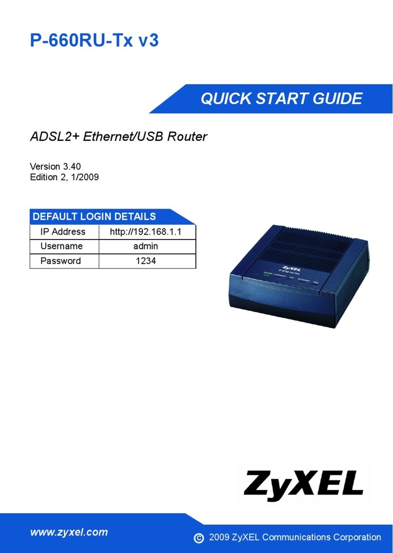
Prestige 650 Series User’s Guide
Table of Contents vii
4.3 DNS Server Address Assignment ..............................................................................................4-2
4.4 LAN TCP/IP ..............................................................................................................................4-2
4.5 Configuring LAN .......................................................................................................................4-4
Chapter 5 Wireless LAN Setup...................................................................................................................5-1
5.1 Wireless LAN Overview............................................................................................................5-1
5.2 Levels of Security ......................................................................................................................5-3
5.3 Data Encryption with WEP........................................................................................................5-4
5.4 Inserting a PCMCIA Wireless LAN Card..................................................................................5-4
5.5 Configuring Wireless LAN ........................................................................................................5-4
5.6 Configuring MAC Filter.............................................................................................................5-7
5.7 802.1x Overview ........................................................................................................................5-9
5.8 Introduction to RADIUS ............................................................................................................5-9
5.9 Configuring 802.1x ..................................................................................................................5-11
5.10 Configuring Local User Authentication ...................................................................................5-13
5.11 Configuring RADIUS ..............................................................................................................5-15
Chapter 6 WAN Setup .................................................................................................................................6-1
6.1 WAN Overview .........................................................................................................................6-1
6.2 PPPoE Encapsulation .................................................................................................................6-1
6.3 PPTP Encapsulation ...................................................................................................................6-1
6.4 Traffic Shaping...........................................................................................................................6-2
6.5 Configuring WAN Setup............................................................................................................6-2
NAT, Dynamic DNS and Time Zone........................................................................................................... III
Chapter 7 Network Address Translation (NAT)........................................................................................7-1
7.1 NAT Overview...........................................................................................................................7-1
7.2 SUA (Single User Account) Versus NAT..................................................................................7-4
7.3 SUA Server ................................................................................................................................7-5
7.4 Selecting the NAT Mode............................................................................................................7-7
7.5 Configuring SUA Server............................................................................................................7-8
7.6 Configuring Address Mapping.................................................................................................7-10
7.7 Editing an Address Mapping Rule ...........................................................................................7-12
Chapter 8 Dynamic DNS Setup...................................................................................................................8-1
8.1 Dynamic DNS ............................................................................................................................8-1
8.2 Configuring Dynamic DNS........................................................................................................8-1
Chapter 9 Time and Date Setup..................................................................................................................9-1
9.1 Configuring Time Zone..............................................................................................................9-1
Remote Management and UPnP................................................................................................................. IV
Chapter 10 Remote Management Configuration ....................................................................................10-1
10.1 Remote Management Overview...............................................................................................10-1
10.2 Telnet .......................................................................................................................................10-2
10.3 FTP...........................................................................................................................................10-2
10.4 Web ..........................................................................................................................................10-2
