3M XT-1 Service manual

3M™ Wireless Communication System Model XT-1
Headset Service Procedures – Using assemblies
TechnicalBulletin - #140
Thedocumentbelow
Lists the 3M™WirelessCommunicationSystem ModelXT-1 headsetassembliesavailable for servicing(with 3M OEM SKUs)
Describesthe standard procedurefor conductingbreak-fix and maintenancetasks on the 3M™WirelessCommunication
SystemModelXT-1 headsetusing readily availableassembliesfrom 3M
Only 3M OEM parts (SKU‘s listed below) should be used for servicing. These proceduresshould be conducted in a repair center
facility.
.
3M™ Wireless Communication System Model XT-1 Headset Service Parts – Assemblies
3M™ Wireless Communication System Model XT-1 Headset Standard Break-Fix Service Procedures
1. Replacingthe Ear Cup and/or Ear Pad and/or Head Pad and/or MicrophoneWindscreen.
2. Replacingthe Inner Case Assembly, OuterCase Assembly,and Boom MicrophoneAssembly.
3. ReplacingBattery Latch Parts, Battery Latch Spring, or BatteryHolder PWA.
4. Replacingthe Headband Assembly.
5. Replacingthe Indicator LED Lens and the Programming StationIR Lens.

Replacing the Ear Cup and/or Ear Pad and/or Head Pad and/or Microphone Windscreen
Replacing the Ear Cup and/or Ear Pad
ToolsRequired:None
3M OEM Parts and SKUs:
Procedure:
1. To replacethe ear cup or ear pad, use your fingers to twist and pull the ear cup
and ear pad together,from the speaker on the headset case.
2. Gently separate the ear pad from the ear cup.
Replace the damagedear pad and/or ear cup with a new one and reassemble.
3. Align the assembledear cup and ear pad with the headset speaker,then
twist and press into place.
Replacing the Head Pad:
ToolsRequired:None
3M OEM Parts and SKUs:
Procedure:
1. To replacethe head pad,use your fingers to peel the oldpad away from the battery case.
Clean off all adhesive residueremaining on the surface.
2. Removethe protectivebacking from a new self-adhesive head pad and
press into place on the insidesurfaceof the batterycase.
Replace Microphone Windscreen on the headset
ToolsRequired:None
3M OEM Parts and SKUs:
Procedure:
1. Removethe old microphonewindscreen from the headset.
2. Installthe replacementmicrophonewindscreenfrom the manager’skit by stretching the opening
of new windscreen and slideover Microphone.
Ear Pad
Ear Cup
Headset Speaker
Head Pad
FIGURE 1
FIGURE 2-a
FIGURE 2-b
Microphone Windscreen

Speaker Wiring
Connector
FIGURE 6
Replacingthe Inner Case Assembly, Outer Case Assembly, and Boom Microphone Assembly
Replacing the Inner Case Assembly
ToolsRequired:
1- Small size Phillipsscrewdriver
1- External retainingring removal tool
3M OEM Parts and SKUs:
Procedure:
1. Make sure power is off and remove the battery from the headsetas illustrated in Fig 3.
2. Removethe ear pad by usingyour fingersto pull the ear pad from the ear cup.
Then grasp the headsetfirmly in one hand, and pull the ear cup off the speaker
with the fingers of the otherhand. See Fig 4.
3. To disassemblethe electronics side of the headsetbeginby removingthe three
screws shown in the illustrationin Fig 5.
4. Carefully separatethe inner and outer halvesof the case assembly.
Support the InnerCase so the speakercable is not strained.
5. Removethe speakerwiringconnectorfromthe main circuitboard. See Fig 6.
6. To install the newreplacementInner Case, connect the speakerwiring connector
on the speaker wires to the connectoron the main circuit board.
7. Make sure the LED Lens is still in place. Otherwise,followthe procedure
Replacing the Indicator LED Lens to re-install the LED Lens.
8. Bring the two halves together and replace the screws as shown in Fig 5.
9. Reinstallthe battery(Fig 7) and checkoperationof the headset prior to returning
it to regular operation.
Important Note:
Be careful to avoid pinching wires between case halves when
reassembling the electronics case. Damaged wiring may cause the
headset to fail during use.
Important Note:
It is important to disconnect the speaker from the main circuit
board as soon as the inner and outer case are separated to avoid
stress on the wires inside the sealed enclosure. Replace the entire
inner case assembly if the wires are broken at the speaker.
FIGURE 3
FIGURE 4
FIGURE 7
FIGURE 5

Replacing Boom Microphone Assembly
ToolsRequired:
1- Small size Phillipsscrewdriver
1- External retainingring removal tool
3M OEM Parts and SKUs:
Procedure:
1. Repeat steps1-4 from the previousprocedureReplacing Inner Case Assembly.
2. DisconnectMicrophone Boom Assembly wires by pullingthe connectoroff
the main circuit board. See Fig 8.
3. Locateand removethe retainingring using the retaining ring tool. See illustration.
4. Removethe clip, nylonwasher and boom microphone assembly.
5. Install replacementboom microphoneby performing steps1-3 in reverse order.
6. Reinstallthe batteryandcheck operation of the headsetprior to
returning it to regular operation.
Replacing Outer Case Assembly
ToolsRequired:
1- Small size Phillipsscrewdriver
3M OEM Parts and SKUs:
Procedure:
1. Replacethe OuterCase Assembly as follows:
a. Removethe boom microphoneassembly as describedin the previous
procedure andinstall it in the new replacementouter case.
b. Connectthe connector on the boom microphonewires to the
connectoron the main circuit board.
c. Reassemblethe inner and outer case halvesby bringing the two halves
together and replacethe screws as shownin Fig 9.
2. Make sure the LED Lens is still in place. Otherwise,followthe procedure
Replacing the Indicator LED Lens to re-install the LED Lens.
3. Reinstallthe battery(Fig 10) and checkoperation of the headset priorto
returning it to regular operation.
Important Note:
Make sure you set the retaining ring tool adjustment screw to
limit how far the retaining ring is expanded. Unless this is done,
the retaining ring will stretch out of shape to a point where it will
not stay in its groove.
Microphone
Assembly Connector
Retaining Ring
Clip
Nylon Washer
FIGURE 8
Boom Microphone Assembly
FIGURE 9
FIGURE 10
PC Board

Replacing Battery Latch Parts (Battery Button, Battery Latch, or Battery Latch Spring)
and /or Battery Holder PWA (Printed Wiring Assembly)
Replacing Battery Latch Parts
ToolsRequired:
1- Number 0 Phillips Screwdriver
1- Tweezers
1- Small size Phillipsscrewdriver
3M OEM Parts and SKUs:
Procedures:
1. Make sure power is off and remove the battery from the headset.See Fig 16.
2. Disassemblethe battery housing sideof the headsetby removing
screws as shown in the illustration.See Fig 17.
3. Carefully separatethe two halves of the housing.See Fig 18-a.
4. Holdingthe battery half of the housing in one hand,carefully separate
the Battery Latch from the Battery LatchButton. See Fig 18-b.
NOTE: It may be necessary to compressthe two retainer posts on
the Battery LatchButton to release the Battery Latch.
5. Removeand set asidethe two piecesthat makeup the button/latchassembly.
6. Locatethe springin the housing and remove it using a tweezersor
equivalenttool, to grasp and lift the spring up and away from the housing.See Fig 19.
7. Replaceany broken Battery Latchparts (Battery Button, Latch,or Spring)
and reassembleonto the battery housing performingsteps 1-6 in
reverse order.
FIGURE 16
FIGURE 17
FIGURE 18-a
Battery Latch Battery Latch Spring
Battery Latch Button
FIGURE 19
Battery half
of housing
Battery
Cover
FIGURE 18-b

Replacing Battery Holder PWA (Printed Wiring Assembly)
ToolsRequired:
1- Number 0 Phillips Screwdriver
1- Solderingiron
1- Small size Phillipsscrewdriver
3MTM ¼’’ PolyimideFilm Tape (SKU# 70-0160-3918-5)
3M OEM Parts and SKUs:
Procedure:
1. Make sure power is off and remove the battery from the headset.See Fig 16.
2. Disassemblethe battery housing sideof the headsetby removing
screws as shown in the illustration.See Fig 17.
3. Carefully separatethe two halves of the housing.See Fig 18.
4. Carefully pull the Battery Holder PWA off the mountingposts.See Fig 20.
5. Use a solderingiron to removethe two wiresfrom the PWA, Fig 21-a
Remove the defectivePWA from the housing and discard.
6. Install a replacementBattery Holder PWA by solderingthe red wire to
the (+) connectionpoint and the black wire to the (-) connection point.See Fig 21-b.
7. Make sure the wires are centered to the headband and
wind around the guide posts as illustratedin Fig 22.
NOTE: Use a small piece of doublesidedtape (illustratedin
Blue in Fig 22) on the end of the metal headbandto
ensure the wire is centered.
Doing this avoidsany possibilityof the wires getting
pinched when reassemblingthe Battery Cover.
8. Apply a strip of 3MTM ¼’’ PolyimideFilm Tape to make
sure the wires are held in place as shownin Fig 22.
9. Reassemblethe battery cover and replace the screws. See Fig 23.
Mounting Posts
FIGURE 20
FIGURE 21-a
+
_
Battery Holder PWA
FIGURE 23
Soldering Iron
Battery half
of housing
Battery
Cover
FIGURE 21-b
FIGURE 22
3MTM 1/4’’ Polyimide
Film Tape
Headband
Guide Posts
Double Sided Tape

Replacing the Headband Assembly
ToolsRequired:
1- Small size PhillipsScrewdriver
1- Tweezers
1- Solderingiron
3MTM ¼’’ PolyimideFilm Tape (SKU# 70-0160-3918-5)
3M OEM Parts and SKUs:
Procedure:
Replacingthe Headband Assemblyrequiresyou to disassemble
both the ElectronicsSide and the Battery Housing Side of the headset.See Fig 24.
Battery Housing Side:
You may followthe first 5 stepsoutlinedin the procedureReplacing Battery
PWA (Printed Wiring Assembly). Or, alternatively, followthe steps outlined below.
1. Make sure the power is off and remove the battery from the headset.See Fig 25.
2. Disassemblethe battery housing sideof the headsetby removing
screws and carefullyseparating the two halves of the housing.See Fig 26.
3. Carefully pull the Battery Holder PWA off the mountingposts,and
use a soldering iron to remove the two wires from the PWA. See Fig 27.
4. Install a replacementheadband assemblyby solderingthe Red wire
to the (+) connectionpoint on the Battery Holder PWA, and the black wire
to the (-) connectionpoint. See Fig 28.
5. Repositionthe Battery Holder PWA on the mountingposts of the
battery halfof the housing.
6. Make sure the wires are centered to the headband and
wind around the guide posts as illustratedin Fig 29.
NOTE: Use a small piece of doublesided tape (illustratedin Blue in Fig 29)
on the end of the metal headbandto ensure the wire is centered.
Doing this avoidsany possibilityof the wires getting pinchedwhen
reassemblingthe Battery Cover.
7. Apply a strip of 3MTM ¼’’ PolyimideFilm Tape to make
sure the wires are held in place as shownin Fig 29.
8. Reassemblethe battery cover and replace the screws.
FIGURE 25
Electronics Side Battery Housing Side
FIGURE 24
Battery half
of housing
Battery
Cover
FIGURE 26
Mounting
Posts
FIGURE 27
Battery Holder PWA
FIGURE 29
3MTM 1/4’’ Polyimide Film Tape
Headband
+
_
FIGURE 28
Guide Posts
Double Sided Tape

ElectronicsSide:
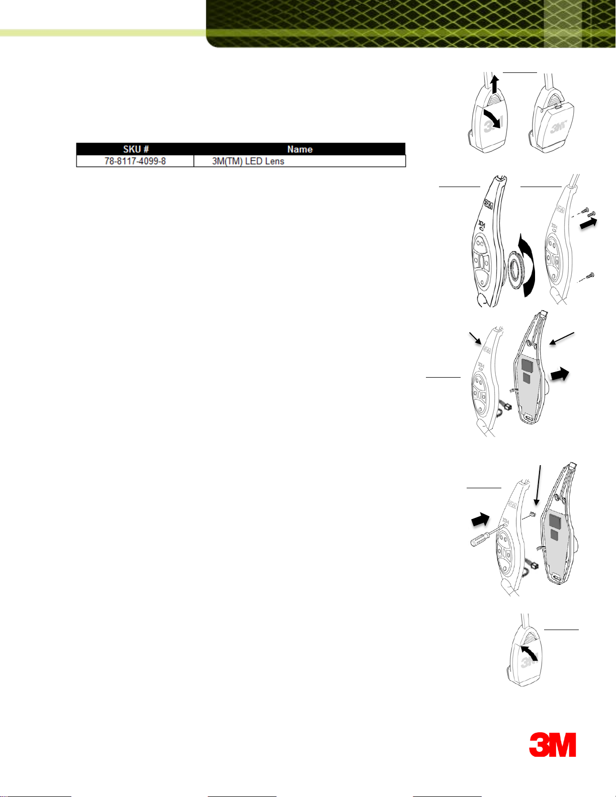
1. Removethe ear pad, ear cup, and the three screws fromthe inner case of the headset.
.
2. Separatethe case halves, ever so slightly.Carefullyraisethe inner case just over
the On-Off buttonand slide down slightly to separate.See Fig 31-a.
Support the innercase so the speakerwires are not strained.
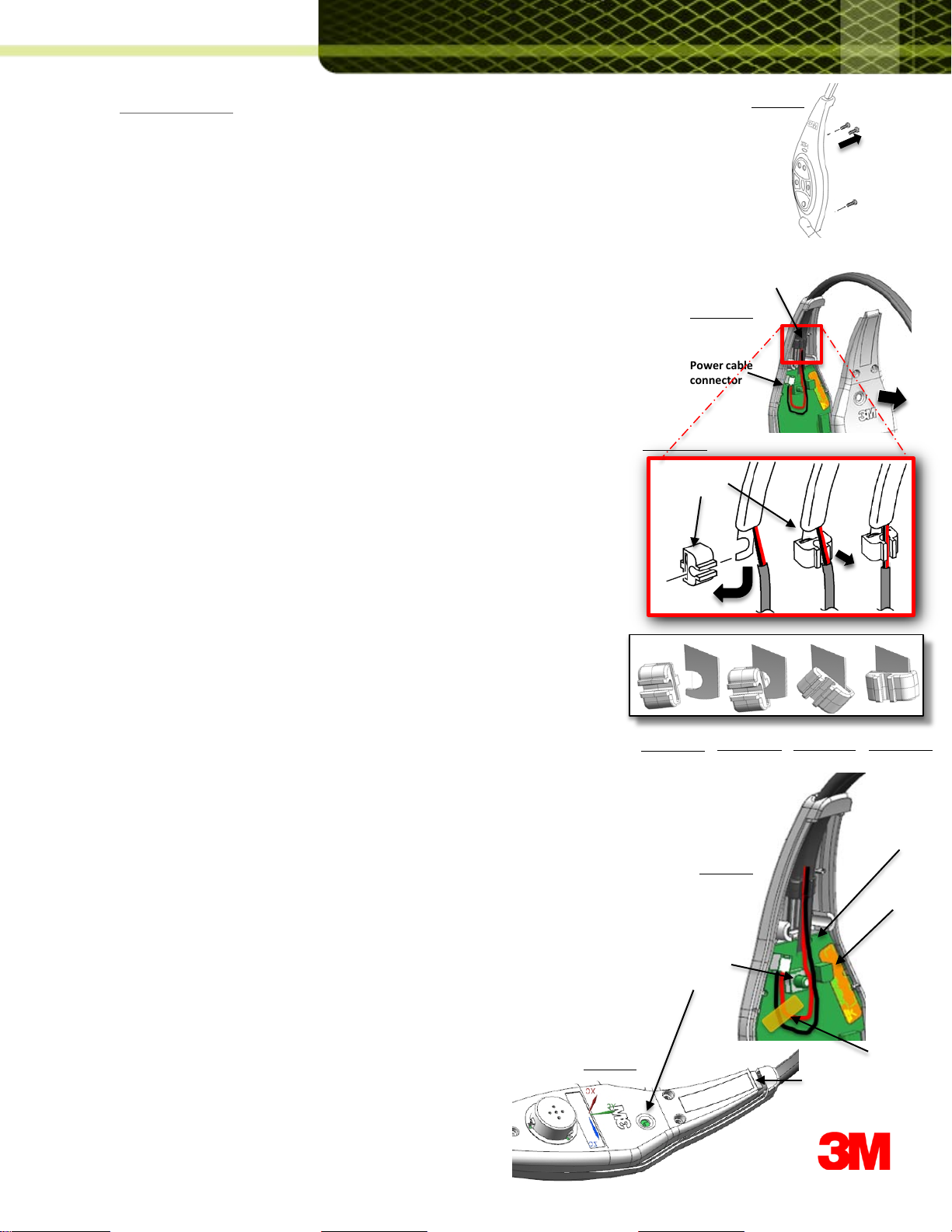
4. Disconnectthe headband's power wiring connectorlocatedat the
top of the main circuit board. See Fig 31-a.
5. Locatethe headbandclip positioned just underthe headbandentry
opening on the outer case assembly.
6.Carefullypull the power wire cable out of the top grooveof the headbandclip.
See Fig 31-b.
7. Removethe headbandclip from the headband end by rotatingit 90 degrees
and pulling it free of the headband.See Fig 31-b and Figs 32-a,b,cand d.
8. Pull the headbandassembly (including the wiring cable) free of the outer case.
9. Insert the power cable from the replacementHeadband throughthe top of the
outer case.
Hold replacementHeadband Clip with the open wire groove facing up.
Hold the Clip so the curved portioninside the slot of the Clip faces next to the
curved sectionof the Headband end. See Fig 32-a.
Rotate the Clip 90 degreesas youslide it into the curvedsectionof
the Headbandendas shown in illustration.See Fig 32-b,32-c and 32-d.
10.Carefullypress the power wires, one on top of the other, into the
top wire groove of the Clip.
Be sure to press the wires completelydown into the wire groove.
11.Plugin the power cableconnector.
Route the power cablebetween the On-Off buttonand the large
capacitor on the PWA. See Fig 33.
NOTE: The power cable MUST routedown the center of the PWA or
the Headbandwill not extendproperly.
12.Applya strip of 3MTM ¼’’PolyimideFilm Tape to make sure the wires are
held in place as shown in Fig 29.
13. Makesure the LED Lens is still in place.Otherwise,follow the procedure
Replacing the IndicatorLED Lens to re-install the LED Lens.
14.Assemblethe case halves by insertingthe tab at the top of the inner case
through the slot at the top of the outer case and carefullylower it over
the On-Off buttonand snapit shut at the bottom. See Fig 34.
Care must be taken not to pinch anywires.
15.Replacethree case screws, ear cup, andpad.
FIGURE 31-a
FIGURE 30
Power cable
connector
Headband
Clip
FIGURE 32-a FIGURE 32-b FIGURE 32-c
Center of
the PWA
Large
capacitor
On-Off
button
Tab on top of the
inner case
FIGURE 33
FIGURE 34
3MTM 1/4’’
Polyimide Film
Tape
FIGURE 32-d
FIGURE 31-b
Headband
Clip

Replacing the Indicator LED Lens:
ToolsRequired:
1- Small size PhillipsScrewdriver
3M OEM Parts and SKUs:
Procedure:
1. Make sure the power is off and remove the battery from the headset.See Fig 11
2. Removethe ear pad by usingyour fingersto pull the ear pad from the ear cup.
Then grasp the headsetfirmly in one hand, and pull the ear cup off the speaker
with the fingers of the otherhand. See Fig 12-a
3. Disassemblethe earpiece side of the headsetby removingscrews shown in Fig 12-b.
4. Carefully separatethe inner and outer caseassembly.See Fig 13
5. Use the tip of a small screwdriverto gently push the lens out of the housing.See Fig 14
6. Replacethe removedindicatorLED lens.
7. Reassemblethe inner and outer case halves by bringingthe two halves
together and replacethe three screws.
8. Reinstallthe battery(Fig 15) and checkoperation of the
headset prior to returning it to regular operation.
FIGURE 11
FIGURE 12-a
FIGURE 13
Indicator LED Lens
Outer Case Inner Case
FIGURE 14
FIGURE 15
FIGURE 12-b

3Mis a trademarkof 3M. Used underlicense in Canada
Pleaserecycle. Printed in USA.
© 3M 2012.All rights reserved.
Contactyour local dealer or 3M to learn more
abouthow we can improveyour business.
www.3M.com/XT1
Building and Commercial
Services Division
3MCenter,Building 223-2N-21
St. Paul, MN 55144-1000
USA
www.3M.com/XT1
TechnicalInformation:The technical information, recommendations and other statements contained in this document are based upon tests or experience that 3M
believes are reliable, but the accuracy or completeness of such information is not guaranteed.
Product Use: Many factors beyond 3M's control and uniquely within user's knowledge and control can affect the use and performance of a 3M product in a
particular application. Given the variety of factors that can affect the use and performance of a 3M product, user is solely responsible for evaluating the 3M product
and determining whether it is fit for user's particular purpose and suitable for user's method of application.
Warranty, Limited Remedy, and Disclaimer: 3M warrants that its intercom products will be free from defects in material and manufacture for the period indicated
in product literature from the date of shipment to purchaser by 3M or its authorized dealer. 3M MAKES NO OTHER EXPRESS OR IMPLIED WARRANTIES,
INCLUDING ANY IMPLIED WARRANTY OF MERCHANTABILITY OR FITNESS FOR A PARTICULAR PURPOSE. If the 3M intercom product does not conform to
this warranty, the sole and exclusive remedy is, at 3M’s option, repair or replacement of the 3M product or refund of the purchase price. This warranty does not
cover: (1) the cost of shipping products to or from 3M for repair, (2) repair or replacement of existing cable or wiring, (3) product failure caused by misuse, abuse,
improper installation, or unapproved modifications, or (4) intercom products that are installed or serviced by a non-3M authorized party. To obtain warranty service,
please contact your authorized 3M dealer or 3M Building & Commercial Services Division, 3M Center, Building 500-01-01, St. Paul, Minnesota 55144-1000.
Limitation of Liability: Except where prohibited by law, 3M willnot be liable for any loss or damage arising from its intercom products, whether direct, indirect,
special, incidental or consequential, regardless of the legal theory asserted.
Other manuals for XT-1
9
Other 3M Conference System manuals
Popular Conference System manuals by other brands

Wheatstone
Wheatstone TALENT STATION TS-4 Technical manual

K-Tech
K-Tech ET401 Quick programming guide

Sony
Sony SX-1070A Instructions for use

Grandstream Networks
Grandstream Networks GVC3210 RMT Administration guide

Grandstream Networks
Grandstream Networks GVC3220 user guide

FONESTAR
FONESTAR SCD-600 instruction manual