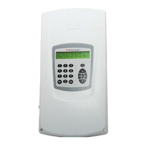
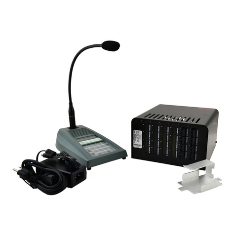
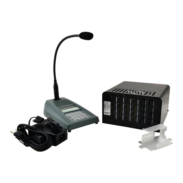
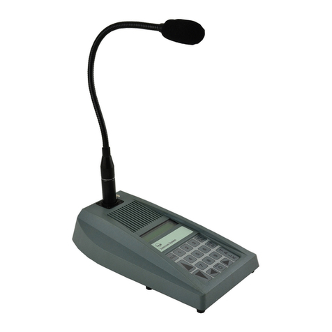
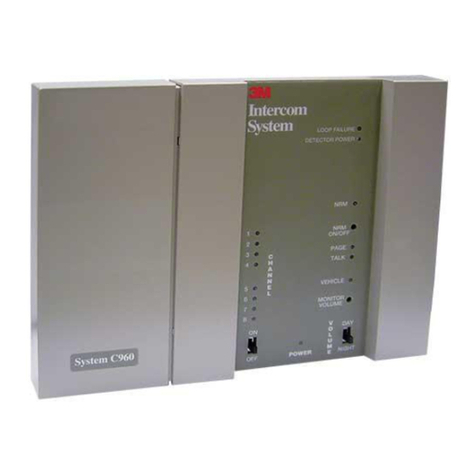
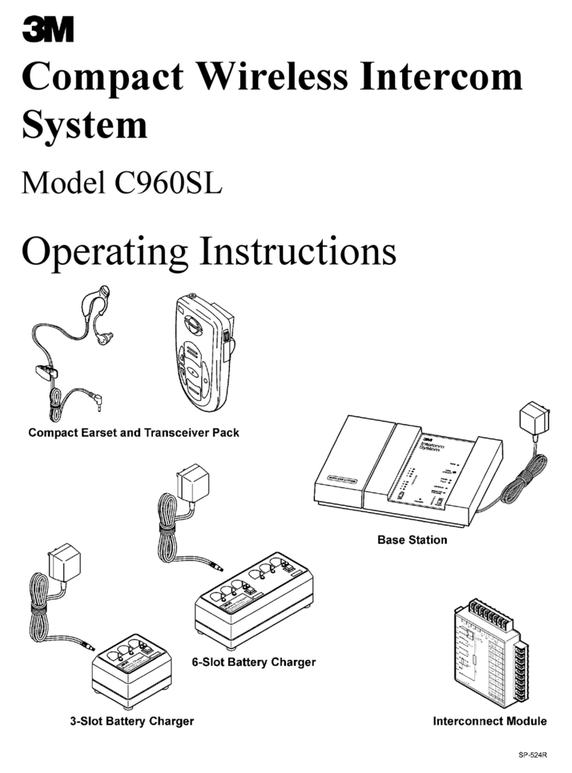
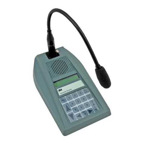
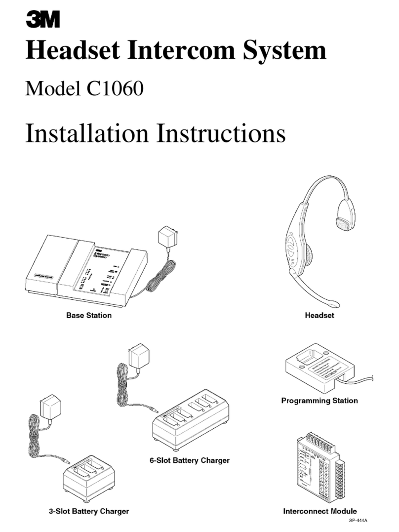
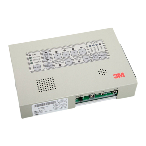
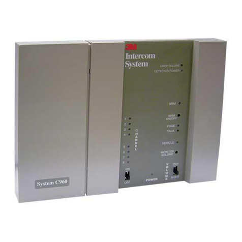
3M C960 Operating and installation instructions

Model C960
Headset Intercom System
Service Information
Food Services Trade Department
3M Center
St. Paul, MN 55144-1000
PrintedinU.S.A.
Copyright E3M IPC. All Rights Reserved.
78-6912-0673-0 Rev C

ModelC960 HeadsetIntercomSystemRevisionHistory
E3M2000 Maya
ThismanualwaspublishedinSeptember,1997 atrevision levelA.
Someportionsofthismanualarealsopublishedseparately.Thepublishingdatesforthefrontmatter,individual
sections,and separately-published documentsare asfollows:
FrontMatter
Cover2000 May......................................................
Revision HistoryPage2000 May..........................................
TableofContents2000 May.............................................
Section1
Operation and Diagrams2000 May........................................
Section2
C960/860 Installation Instructions(78-6912-0672-2)2000 May.................
Section3
ReplacementPartsand Service 2000 May...................................
Section4
Troubleshooting Guide(78-6912-0680-5)2000 May..........................
Analyzing Batteries1997 September............................................
Section5
Operating Instructions(78-6912-0671-4)2000 May...........................
InstallationProcedures:
NoiseReduction Module,ModelA121 (78-6912-0699--5)1999 November.............
NoiseReduction Module,ModelA125 (78--6912--0723--3)2000 March.............
Loop Detector,ModelsA200 and A201 (78--6912--0712--6)2000 April............
AudioGreeter,ModelA300 (78--6912--0717--5)2000 February.....................
DuplexMicrophone/SpeakerAssembly(78-6912-0490-9)1995 August..............
Cross-LaneModule(78-6912-0487-5)1995 March.............................
HeadsetStorageRackKit (78-6912-0508-8)1995 March........................
DuplexMenu Cable(78-6912-0509-6)1995 March............................
3MCommunicationsBar (78-6912-0581-5)1996 July........................
Five-InchSpeakerand MicAssembly(78--8050--8497--3)1996 April..............
3.5-InchDuplexMicrophone(78--6912--0596--3)1996 June....................
5-InchDuplexSpeakerAsembly(78--6912--0530--2)1999 April..................

ModelC960HeadsetIntercomSystemRevisionHistory
bE3M2000 May
(Blank Page)

ModelC960 HeadsetIntercomSystemTableofContents
i
E3M2000 May
Section1. Operationand Diagrams
Introduction 1-1...................................................................
SystemComponents1-1.............................................................
BaseStation 1-1................................................................
Headset1-1....................................................................
BatteryCharger1-1..............................................................
Speakerand MicrophoneAssemblies1-1.............................................
InterconnectModule1-1..........................................................
Cross-LaneModule1-1...........................................................
VehicleAlertSystem1-1..........................................................
SystemConfigurations1-1...........................................................
Single-LaneStandardCommunication System1-2......................................
Dual-LaneStandardCommunication System1-2.......................................
Single-LaneDuplexCommunication System1-2.......................................
Dual-LaneDuplexCommunication System1-2........................................
Dual-LaneDuplexCross-LaneCommunication System1-2...............................
Operating Theory 1-2...............................................................
Processing VehicleAlertSignals1-2.................................................
Transmitting and Receiving 1-2.....................................................
Talk/ListenCommunication 1-3....................................................
TalkLockMode1-4.............................................................
PageMode1-4.................................................................
PageMonitorMode1-4...........................................................
Cross-LaneTalk/ListenMode1-4...................................................
MonitorAmplifierand Speaker1-4..................................................
HeadsetComponents1-4............................................................
RechargeableBattery 1-5.........................................................
Headband 1-5..................................................................
MicrophoneBoomAssembly 1-5...................................................
SpeakerAssembly 1-5............................................................
BaseStation 1-6...................................................................
DCPower1-6..................................................................
Talk/PageInput1-6..............................................................
VehicleDetector Input1-6.........................................................
Menu MicInput1-7.............................................................

ModelC960 HeadsetIntercomSystemTableofContents
ii E3M2000 May
BaseStation Configuration Jumpersand Switches1-7...................................
BaseStation and ExternalComponentsDiagram1-8.......................................
InterconnectModule1-11.............................................................
On/Off DC1-11.................................................................
Menu MicrophoneSignalControl1-11................................................
Menu SpeakerAudioControl1-11...................................................
MonitorSpeakerAudioControl1-11.................................................
VehicleDetectorSignalDC1-11.....................................................
InterconnectModuleDiagram1-13......................................................
Section2. InstallationInstructions
Section3. ReplacementPartsand Service
Ordering ReplacementParts3-1.......................................................
TechnicalService 3-1...............................................................
Section1-BaseStation Assemblyand InterconnectModule3-2..............................
Section2-HeadsetAssembly 3-4......................................................
Section3-3-SlotBatteryChargerAssembly 3-6..........................................
Section4-6-SlotBatteryChargerAssembly 3-7..........................................
Replacing theHeadsetSpeaker3-8.....................................................
Replacing theMicBoomAssembly 3-11.................................................
Replacing theBatteryTerminals3-12....................................................
Replacing theBatteryReleaseButton Spring 3-13..........................................
Section4. Troubleshooting
Troubleshooting Guide
Analyzing Batteries4-1..............................................................
DISCHARGE Test4-1............................................................
CYCLE 1Test4-1...............................................................
CYCLE 2,CYCLE 3,and CYCLE 4Tests4-1.........................................
Setup Procedures4-2.............................................................
Initiating aTest4-2..............................................................
Interpreting TestReadings4-2......................................................
ErrorCodes4-2.................................................................

ModelC960 HeadsetIntercomSystemTableofContents
iii
E3M2000 May
Section5. Operating and InstallationInstructions
ModelA121 NoiseReduction Module,78-6912-0699--5
ModelA125 NoiseReduction Module,78--6912--0723--3
ModelsA200 and A201 Loop Detector,78--6912--0712--6
ModelA300 AudioGreeter,78--6912--0717--5
ModelC960 Operating Instructions
Cross-LaneModuleInstallation Instructions,78--6912--0487-5
HeadsetStorageRackInstallation Instructions,78--6912--0508-8
DuplexMenu CableInstallation Instructions,78--6912--0509-6
3MCommunicationsBar Installation Instructions,78--6912--0581-5
FiveInchSpeakerand MicAssemblyInstallation Instructions,78--8050--8497-3
3.5-InchDuplexMicrophoneInstallation Instructions,78--6912--0596-3
5--InchDuplexSpeakerAssembly,78--6912--0530-2

ModelC960 HeadsetIntercomSystemTableofContents
ivE3M2000 May
(Blank Page)

ModelC960 HeadsetIntercomSystemOperationandDiagrams
1-1E3M2000 May
Introduction
The3M ModelC960 HeadsetIntercomSystemisa
wirelessintercomsystemdesignedforhighreliability,
compactness,and easeofservice.It isdesignedto
providetwo-way,radio-frequencyaudio
communication in quickservice drive-through
restaurantsand convenience stores.
Thesystemcanbeprogrammedtooperateonanyone
of16differentchannelstoprovidehigh-qualityaudio
performanceandreducethepossibilityofinterference
between neighboring wireless systems.
SystemComponents
Thenumberofcomponentsinasystemvaries
dependingonthesystemconfiguration.However,the
basestation,headset,andbatterychargerarecommon
toall systemconfigurations.
BaseStation
Thewall-mounted basestation containslogic and
analogcircuitsandrelatedsystemcontrols,areceiver
toreceivesignalstransmittedfromtheheadsets,anda
transmittertotransmit signalstotheheadsets.
Headset
Theheadsetisawireless,battery-powered,two-way
radiousedbytheoperatortocommunicatewithmenu
signcustomersandwithotherstorepersonnelwhoare
wearing headsets.Themicrophone and earpiece
enabletheoperatortotransmit and receivespoken
communication and alert tones.
Theheadsetcanbeprogrammedtooperateonanyone
of16differentchannelstoprovidehigh-qualityaudio
performanceandreducethepossibilityofinterference
between neighboring wireless systems.
Theheadsetassembly has severalfield-replaceable
components.These componentsaredetailedin
Section 3 ofthismanual(ReplacementPartsand
Service).
BatteryCharger
Thebatterychargerchargesheadsetbatteriesin
approximately 1.5to 2 hours.The chargeris
availablein 3-slotand 6-slotversions.
Each batterychargerhastwofield-replaceable
components:
SChargerAssembly
STransformerAssembly
Speaker and MicrophoneAssemblies
Standard Systems
The5-InchSpeakerand MicAssemblyis
recommendedforuseinstandardcommunication
systems.Itconsistsofa5-inch,water-resistant,
eight-ohmconespeakerplusaspecial
weather-resistantdynamicmicrophone.Italso
includesamounting bracketforeasymounting in
menu signs,speakerpostsand otherapplications.
Usingthisseparatespeakerand microphoneensures
maximumsound quality.
DuplexSystems
The3.5-InchDuplexMicrophoneand5-InchDuplex
SpeakerAssemblyarerecommendedforuseinduplex
communicationsystems.Themicrophoneismounted
on afoamhousing,whichcanbe cuttotherequired
size.Thespeakerismountedinametalhousing.
InterconnectModule
Thisoptionalmoduleprovidesa convenient
connection pointforequipmentsuchas speakers,
microphones,vehicledetectors,and auxiliary
intercoms.
Cross-Lane Module
Thismoduleisarequiredcomponentfordual-lane
duplexcross-lanecommunicationsystems.Itenables
asingleheadset to operatetwo basestations.
VehicleAlertSystem
TheModelC960 iscompatiblewithall 3Mvehicle
detectorsand thoseofmostothermanufacturers.
Therearetwotypesofvehicledetectors,classifiedas
presence detectorsorpulsedetectors.Presence
detectors(suchasmagneticloopsorSODAR)provide
asignalforaslong asavehicleispresentat the
detector.Pulsedetectors,suchasairhoses,provide
onlyamomentarysignal—signalling vehiclearrival
withnoindication ofwhetherornot thevehicle
remainsat thedetectorstation.
SystemConfigurations
Thesystemcan be configuredin oneof fiveways
dependingonthenumberofmenusignsatthefacility
and thetypeofcommunication desired.

ModelC960HeadsetIntercomSystemOperationand Diagrams
1-2E3M2000 May
Single-LaneStandardCommunication System
This systemprovides standardcommunication
(talk/listen) for facilitiesthathaveonemenusign.It
consistsofonebasestationandoneormoreheadsets
and batterychargers.
Dual-LaneStandardCommunication System
This systemprovides standardcommunication
(talk/listen)forfacilitiesthathavetwomenusigns.It
consistsoftwoindependentsystems-- onededicated
tomenusign 1and theotherdedicatedtomenusign
2.Theheadsetsareprogrammedtoworkwith one
systemortheotherandarelabeledaccordingly(1or
2).
Single-LaneDuplexCommunication System
This systemprovidesduplexcommunication
(simultaneoustalk/listen) for facilitiesthathaveone
menusign.Itconsistsofonebasestationand oneor
moreheadsetsand batterychargers.
Dual-LaneDuplexCommunication System
This systemprovidesduplexcommunication
(simultaneoustalk/listen) for facilitiesthathavetwo
menu signs.Itconsistsoftwo basestationsandtwo
ormoreheadsetsand batterychargers.
Cross-LaneCommunication System
This systemprovidesduplexcommunication
(simultaneoustalk/listen) for facilitiesthathavetwo
menusigns.Itconsistsoftwoduplexsystemsthatare
connectedtoa cross-lanemodule.Theheadsetsare
programmedforeitherlane1 orlane2.
During off-peak hours,the cross-lanemoduleis
turnedontolink thetwosystemsand enableone
operatortotalktocustomersatmenu sign1 ormenu
sign 2 orwith otherheadsetoperators.
Duringpeakhours,thecross-lanemoduleisturnedoff
toseparatethesystems.Withthe cross-lanemodule
off,onesystemisdedicatedtomenu sign1and the
othertomenusign2.Menusign1operatorscantalk
tocustomersatmenu sign 1 orwith otherheadset
operators.Menu sign 2 operatorscantalkto
customersatmenu sign 2 orwith otherheadset
operators.
OperatingTheory
The3M ModelC960 HeadsetIntercomSystemhas
two basicfunctions.First,it processesvehicle alert
signalsthataresuppliedbyahard-wired vehicle
detection system.Second,it transmitsand receives
radiosignalstoprovideoneormoreofthefollowing
typesofaudiocommunication:
STalk/listencommunication
STalklockcommunication
SPage communication
SPagemonitorcommunication
SCross-lanetalk/listencommunication
ProcessingVehicleAlertSignals
TheModelC960 iscompatiblewithall 3Mvehicle
detectorsandthoseofmostothermanufacturers.The
vehicle alertsystemprovidesasignal tothebase
station toindicateacustomerispresentat themenu
sign.
There aretwotypesofvehicledetectors.Presence
detectors (suchasmagneticloopsorSODAR)
provideasignalforaslong asavehicleispresentat
thedetector.Pulsedetectors,suchasairhoses,
provideonlyamomentarysignal—signallingvehicle
arrivalwithnoindication ofwhetherornot the
vehicleremainsat thedetectorstation.
SIfapresencedetectorisused,menusignaudiois
turnedoffautomaticallywhenthevehicleleaves.
SIf apulsedetectorisused,menu sign audiois
silencedbypressingandreleasingaheadsetpage
switch.
Whenavehicledetection signal ispresentedtothe
basestation,thebasestation broadcastsarepeating
alert tonetoall headsets.The alert tone continues
untilthetalkswitch[onanactiveheadset]ispressed.
Transmitting and Receiving
Thetransmitting and receiving functionsare
accomplishedbytwoseparatesetsof radio
transmittersand receivers.Oneset islocatedinthe
headsetand theotherinthebasestation.

ModelC960 HeadsetIntercomSystemOperationandDiagrams
1-3E3M2000 May
Theheadsetreceivesmicrophoneaudiosignalsfrom
thebasestation on frequency Band transmitsboth
audiosignalsandcontrol toneson frequencyA.The
control tonesare abovethe audiblerange,and
functiontoturnthebasestationreceiverONtoenable
reception ofthe audiosignalfromtheheadset
microphone.Becausethecontroltonesareabovethe
audiblerange,audibletonesfromdevices suchas
telephones,pagers,and radioswill not interfere.
Thebasestation transmitson frequency Band
receiveson frequency A.Thereceiverinthebase
station operatesabovethe audiblefrequencyrange.
Whileit receivesthehigh-frequencycontrol tones
fromtheheadset,it isnotaffectedbyaudibletones
fromdevices suchastelephones,pages,andradios.
Thetransmitterinthebasestation isalways
transmitting a “no signal”transmittercarrier,even
whenthereisno microphone audiofromthemenu
sign orheadsetoperatorbeing broadcast.This“no
signal“carrieriscontinuallybroadcasttoandreceived
by all headsetreceivers.Itservestoblock outother
radio-frequencysignalsornoisesfromheadset
receivers.
Similarly,theheadsetreceiverisalwaysONtoenable
thelistenmode.Theheadset transmitterturnsON
onlywhenatalk orpageswitchispressed.
Instandardcommunicationsystems,theoutputfrom
theheadsetreceiverismutedwhentheheadset
transmitterisON.Thisprovides standard
communication (talkorlisten).
In duplexcommunication systems,theoutputfrom
theheadsetreceiverisenabled(notmuted)whenthe
headset transmitterisON.Thisprovidesduplex
communication (simultaneoustalkandlisten).
Thetwosetsoftransmittersand receiverswork
togethertoprovideaudiocommunicationbetweenthe
customeratthemenusign andtheheadsetoperators
insidethedrive-throughrestaurantorbetweentwoor
moreheadsetoperators.
All audiotransmittedbyaheadsetduring talk
operation isheard by:
SMenu sign customers.
SPersonnelwearing activeheadsets.
SPeopleneartheoptionalmonitorspeaker.
All audiofromthemenu sign isheard by:
SPersonnelwearingheadsetsthatareoperatingin
thetalk/listenmode.
SPeopleneartheoptionalmonitorspeaker.
Talk/ListenCommunication
Headset toMenu Sign
Afterthevehicledetection signal ispresentedtothe
basestation,thebasestation broadcastsarepeating
alert tonetoall activeheadsets.
Theheadsetoperatorpressesandholdsthetalkbutton
toacknowledgethe customerat themenu sign and
cancel the alert tone.Whentheheadsetoperator
speaksintothemicrophone,theheadsetgeneratesa
talkcontroltoneandaddsittothemicrophoneaudio.
Themicrophoneaudioandtalkcontroltone arethen
transmittedtothebasestation.Thetalkcontroltone
turnsthebasestation receiverON ,enabling it to
receivethemicrophone audio.
nNote
Thetalkcontrol toneisabovethe audible
frequencyrange,and isusedto prevent thebase
station receiver fromreceivingsignalsfromother
devices(telephones,pagers,etc.)thatmightbeon
thesamefrequency.
Whenthebasestationreceivesthemicrophoneaudio
signal,it re-transmitsit toall headsetreceivers.The
samemicrophone audiosignal isalsoroutedtothe
menu speakeramplifierand themonitorspeaker
amplifier.
Themenu speakeramplifier routesthe amplified
microphoneaudiothroughwiretothemenuspeaker
whereit can beheard bythe customer.Themonitor
speakeramplifier routesthe amplifiedmicrophone
audiothrough wiretoan optionalmonitorspeaker
(typicallylocatedinthekitchenarea)whereitcanbe
heardbyanyoneincloseproximitytothespeaker.
nNote
Themenu sign audioisnot turnedON unlessthe
basestation receivesatalkcontrol tonefromthe
headset.However,thethemonitoramplifieris
alwaysturnedON.
ModelC960HeadsetIntercomSystemOperationand Diagrams
1-4E3M2000 May
Menu SigntoHeadset
Whenthecustomeratthemenusignspeaks,audiois
detectedbyamicrophoneandsentthroughwiretothe
transmitterand themonitoramplifierinthebase
station.
Thetransmittertransmitsthemicrophoneaudiotoall
headsetreceivers.Themonitoramplifier routesthe
samemicrophoneaudiothroughwiretotheoptional
monitorspeaker.
nNote
Personnelwearingheadsetsthatareset tomonitor
only page communicationswill notheartalk
communications.If theheadsetsisinthePage
MonitorMode,the “talk” audio output tothe
headsetspeakerismuted.
TalkLockMode
Thetalklockmodeisusedtooperate“handsfree.”In
thismode,theheadsetautomaticallyswitchesfrom
standby totalk/listenwhena customerisdetectedat
themenu sign.Theheadsetautomaticallyswitches
backtostandby whenthe customerleavesthemenu
sign.Thismodeisonlyavailablewithduplexsystem
configurations.
Page Mode
Whentheheadsetpagebutton ispressed,system
operationisidenticaltotalkoperationexceptfortwo
things:
SThetalk control toneisnotbroadcast,sothe
menu sign amplifierisnot turned on,muting
menu sign audio.
SApage control toneis sentfromtheheadset,
turning on thebasestation transmitter.The
transmitterrebroadcaststhistonetoturnONany
headsetsthatareinthepagemonitormode.Any
audio detectedbytheheadsetmicrophoneis
transmittedtothebasestation whereit is
received,transmittedtootherheadsetsandsentto
themonitorspeakeramplifier.
Page Monitor Mode
Thepagemonitormode allowsheadsetoperatorsto
hearonlypagecommunication.Inthepagemonitor
mode,talkaudiooutputtotheheadsetismuted.Only
internalpage communication isheard becausethe
headsettransmitteristurnedONonlywhenitreceives
apage control tone.Talktransmissionsfromother
headsetsoraudiofromthemenu signarenotheard.
Cross-LaneTalk/ListenMode
Thecross-lanetalk/listenmodeisavailableonlyina
dual-laneduplexcross-lanesystem.The cross-lane
moduleinthissystemenablesthemenusignoperator
toselectivelycommunicate(talkand listen)to
customersineitherlane1orlane2.
WiththeT1(TalkLane1)switchpressed,theheadset
transmitter/receiverswitchestothelane1channel
frequencies,enablingthelane1basestationandlane
1communications.
WiththeT2(TalkLane2)switchpressed,theheadset
transmitter/receiverswitchestothelane2channel
frequencies,enablingthelane2basestationandlane
2communications.
MonitorAmplifier and Speaker
Aone-watt,single-endedmonitoramplifierinthe
basestation powers[an optional]speakerwhichis
capableof reproducing thefollowing signals:
STalkaudio(communicationstothemenuspeaker)
SListenaudio(communication fromthemenu
speaker)
SPage audio(internalstore communications)
SVehicle alert tone
Separatevolume controlsadjust thelevelofeach
signal toachievethedesiredsignalbalance.In
addition,thereisamastervolume controlwhich
adjuststheoverall volumeofthemonitorspeaker.
HeadsetComponents
nNote
Thereceiver/transmitterand logic circuitry
containedintheC960 headsethousing isboth
proprietaryand non-fieldrepairable.
Theheadsetassembly has severalfield-replaceable
components.These componentsaredetailedin
Section 3 ofthismanual(ReplacementPartsand
Service).
Themajorcomponentsare asfollows:

ModelC960 HeadsetIntercomSystemOperationandDiagrams
1-5E3M2000 May
SRechargeableBattery
SHeadband
SMicrophoneBoomAssembly
SSpeakerAssembly
RechargeableBattery
ThenickelmetalhydridebatteryprovidesDCpower
fortheheadsetcircuitry.
Headband
Theheadbandconsistsoftwointerlockingassemblies
thatprovide adjustmentsforheadband widthand
headband size.Bothassembliesarereplaceable.
MicrophoneBoomAssembly
Theboom/earpiece assemblyincludesanelectret
microphone and aspeaker-drivenearpiece.It is
replaceable asaseparateunit.
Speaker Assembly
Thespeakerassemblyishoused betweentheinner
andoutercasesand isreplaceable asaseparateunit.

ModelC960HeadsetIntercomSystemOperationand Diagrams
1-6E3M2000 May
BaseStation
nNote
Receiver/transmitterandlogic circuitrycontained
intheC960 headset intercombasestation isboth
proprietaryand non-fieldrepairable.Forthis
reason,the accompanying basestation diagram
providesno circuitcomponentdetail.Onlythose
detailsthatassistfault isolation (suchas
connections,configurationjumpers,audiocontrol
circuits,replaceablecomponentsandinput/output
functions)areshown.
DC Power
DCpower forthebasestation circuitsand external
componentsisprovidedasfollows:
Aself-containedDCpowertransformer,connectedto
120VAC,providesunregulated+12VDCtothebase
station powerinput jack.The+12VDCisturnedon
oroffbyaslideswitchlocatedonthefrontofthebase
station.Theunregulated+DCisroutedthrough a
protectivepolyswitch(circuit breaker) tocircuit
componentsand avoltageregulator (called power
supplyinthediagram).If an overcurrentcondition
causesthepolyswitchtoopen,itautomaticallyresets
afterpowerisremoved.
Theunregulated+12VDCisusedbythevehicle
detectortoprovidea+DCvehicledetectsignaltothe
basestationvehicledetectcircuits.Ifaninterconnect
moduleisusedinthesystem,unregulated+DCis
providedtoenergizetheinterconnectmodulerelays.
Talk/PageInput
Talkandpagevoicecommunicationstransmittedfrom
theheadsetarereceivedalong withtheir
accompanying “talk”or“page” control tones.
Receivedtalkcommunicationsareroutedbythe
RCVR&RCVRLOGICasfollows:
STothemenu sign speakeramplifierviathe
DAY/NIGHTvolumecontrolsandDAY/NIGHT
switch,through the amplifiertothemenu sign
STothemonitorspeakeramplifierviatheMON
TALKvolumecontrol,throughtheamplifierand
theMasterMonitorVolumecontroltothemonitor
speaker
SThrough thetransmit amplifiertotheTXMT&
TXMT LOGICfortransmission toall headset
receiversandtooutputconnectorpin9forusein
cross-lane applications
Received page communicationsareroutedbythe
RCVR&RCVRLOGICasfollows:
STothemonitorspeakeramplifierviatheMON
PAGEvolumecontrol,throughtheamplifierand
theMasterMonitorVolumecontroltothemonitor
speaker
SThrough thetransmit amplifiertotheTXMT&
TXMT LOGICfortransmission toall headset
receivers,andtooutputconnectorpin9forusein
cross-lane applications
VehicleDetectorInput
Upon detection ofavehicle,thevehicledetector
signalwill beasteady DCorashort-duration DC
pulsedependingonwhetherthevehicledetectorisa
“presence”or“pulse”typedetector.Uponreceiptof
thevehicledetectsignal,theVEHICLE DETECT
LOGICcircuitemitsalerttones.Thesealerttonesare
routedasfollows:
STothemonitorspeakeramplifierviatheMON
ALERTvolume control,through themonitor
speakeramplifierandtheMasterMonitorvolume
control tothemonitorspeaker
STothetransmit amplifierviatheHeadsetAlert
Levelcontrol,throughtheamplifiertotheTXMT
&TXMT LOGICfortransmission toall headset
receivers
STo outputconnectorpin12foruseincross-lane
applications

ModelC960 HeadsetIntercomSystemOperationandDiagrams
1-7E3M2000 May
nNote
ThevehicledetectPULSE/PRESENCEjumperJ4
mustbesetappropriatelyand its setting
programmedintothebasestationlogicforcorrect
vehicledetection and alert tonesto occur.For
furtherexplanation ofvehicledetectalert tones,
refertotheVehicleAlertSystem,Thevehicle
detectPULSE/PRESENCEjumperJ4mustbeset
appropriatelyand its settingprogrammedintothe
basestationlogicforcorrectvehicledetectionand
alert tonesto occur.For furtherexplanation of
vehicledetectalert tones,refertotheparagraphs
titledVehicleAlertSystemand VehicleDetector
Inputinthis section.
Menu MicInput
Audiofromthemenusignmaycomefromoneoftwo
sources:a combination speaker/microphone(the
MENU SIGN SPEAKER)oraseparatedynamic
microphone(theMENU MIC).TheMIC/SPKR
jumpersJ1andJ2mustbesetaccordingly;bothmust
besettotheMICposition ifaseparateoutsidemicis
used,totheSPKRposition ifa combination outside
speaker/mic(OSM)isused.Depending on jumper
positions,micinput isroutedtothemic amplifier,
through the amplifierand itsMenu MicSensitivity
controland then:
STothemonitorspeakeramplifierviatheMONIN
volume control,through themonitorspeaker
amplifierandtheMasterMonitorvolumecontrol
tothemonitorspeaker
SThrough thetransmit amplifiertotheTXMT
&TXMT LOGICfortransmission toall headset
receivers,andtooutputconnectorpin9forusein
cross-lane applications
BaseStationConfigurationJumpersand
Switches
ConfigurationJumpers
Jumpers J1and J2areusedtoconfigurethebase
station forusewitheitheraseparateoutside
microphoneora combination outsidespeaker/mic
(OSM).Unlikejumpers J3,J4and J5whichaffect
logicinput levels,jumpers J1and J2simplyswitch
themicrophone amplifierinputstoeitherthe
microphoneorOSM.Setbothjumperstojumperpins
2and3forusewithaseparateoutsidemic,orto
jumperpins1and2fora combination speaker/mic
(OSM).
JumperJ3isusedtoconfigurethebasestationforuse
inacross-lane,dual-lanecommunicationssystem.In
suchasystem,onebasestationmustbesetforlane1
frequencycommunications,theotherbasestation
mustbesetforlane2frequencycommunications.
JumperJ3pins1and2(forcingtherelatedlogicinput
high)forlane1configuration.JumperJ3pins2and3
(forcing therelatedlogicinput low) forlane2
configuration.WheneverjumperJ3ischanged,you
mustpressthebasestationRESETswitchtoprogram
thenewjumpersetting intothebasestation
microprocessor.
nNote
Itmayalso benecessarytore-programsystem
headsets,depending on systemconfiguration.
RefertotheC960InstallationInstructionsformore
information.
JumperJ4isusedtoconfigurethebasestationforuse
witheitherapresencetypevehicledetectororapulse
typevehicledetector.JumperJ4pins1and2(forcing
therelatedlogicinputhigh) forapresence type
detector.JumperJ4pins2and 3(forcing therelated
logicinputlow)forapulsetypedetector.Whenever
jumperJ4ischanged,youmustpressthebasestation
RESETswitchtoprogramthenewjumpersettinginto
thebasestation microprocessor.
JumperJ5isusedtoconfigurethebasestationsothat
itcaninturn,programtheheadsetsforstandard(talk,
thenlisten,thentalketc.)communicationsor for
duplex(simultaneoustalkand listen)
communications.Duringstandardcommunications,
headsetreceiveroutput ismuted during talk
transmissions.During duplexcommunications,
headsetreceiveroutput isnotmuted during talk
transmissions.Theheadsetreceivermute/notmute
(standard/duplex)command is sent totheheadset
logicduring headsetprogramming—determined by
thejumperJ5setting.WheneverJumperJ5is

ModelC960HeadsetIntercomSystemOperationand Diagrams
1-8E3M2000 May
changed,you mustpress thebasestation RESET
switchto programthenewjumpersetting intothe
basestation microprocessor.
nNote
WhenjumperJ5ischanged,you mustalso
reprogramthesystemheadsets.RefertotheC960
Installation Instructionsformoreinformation.
Configuration Switches
RESET SWITCH:Very briefly,actuation ofthe
RESET SWITCHclearslogicinputsoftheir
establishedlevelsandlatchesthelogicinputsattheir
newlevels.
CHANNELSELECTSWITCH:TheC960 systemis
capableofoperating on eightdifferentchannelsfor
each oftwolanes.Thisprovidesatotalof16
operating channels since eachsystem may be
designatedasalane1 orlane2system.Each
operating channel iscomprised ofa “set”oftwo
frequencies,onefor receiving,onefortransmitting.
Thechannelfrequenciesarepreprogrammedinboth
thebasestation and headsetmicroprocessors.Each
actuationoftheCHANNELSELECTswitchprompts
thebasestationmicroprocessortoadvancetothenext
available channel.Afteranewchannel is selected,
you mustreprogramall systemheadsetstothenew
channel.(Headsetscanoperateonlyonlane1orlane
2channelsunless theyareusedwithanaccessory
cross-lanemodule.)Formoreinformationonchannel
selection and reprogrammning,refertotheC960
Installation Instructions.

Model C960 Headset Intercom System Operation and Diagrams
1-9
E3M 2000 May
Base Station and External Components Diagram

Model C960 Headset Intercom System
Operation and Diagrams
1-10 E3M 2000 May
(Blank Page)

ModelC960 HeadsetIntercomSystemOperationandDiagrams
1-11E3M2000 May
InterconnectModule
AninterconnectmoduleisneededwhenaC960
HeadsetIntercomsystemincludesanauxiliary
intercomtoprovidecontinuedcommunicationswhen
theprimaryintercomneeds service.
The auxiliaryintercom may beaconventional,
hard-wiredintercomoritmaybeasecondC960base
station.
Externalsystemcomponents(speakers,microphone,
vehicledetector) connect tointerconnectmodule
connectorJ302.Basestation inputsand outputs
(power,common,menu mic,menu speaker,vehicle
detector) connect tointerconnectmodule connector
J303.Auxiliaryintercom(orsecond basestation)
inputsand outputsconnect tointerconnectmodule
connectorJ301.
On/Off DC
Intheinterconnectmoduleschematicdiagram,the
interconnectmoduleis showninits“on”state,with
relaysenergized.
On/Offcontroloftheinterconnectmoduleisprovided
by (thepresence orabsence of) +12VDCfromthe
(primary)basestation.With basestation +12VDC
present(viaJ303 pins1and 2),relaysK301,K302
andK303energizetoswitchmicrophone,speakerand
vehicledetectsignalsto/fromthebasestation.Ifthe
basestation-providedDCisnotpresent(basestation
turnedoff),relaysK301,K302andK303de-energize
totheswitchthesamesignalsto/fromthe auxiliary
intercom.
Menu MicrophoneSignalControl
RelaycontactsK301-Aand K301-Bcontrol
distribution ofthemenu micsignal(s).Withrelay
K301 energized,themenu micisconnectedtothe
basestation inputs.WithRelayK301de-energized,
themenumicisconnectedtothe auxiliaryintercom.
Menu Speaker AudioControl
RelaycontactsK302-Aand K302-Bcontrol
distribution ofthemenu speakeraudio.Withrelay
K302energized,themenuspeakerisconnectedtothe
basestation.WithrelayK302de-energized,themenu
speakerisconnectedtothe auxiliaryintercom.
MonitorSpeaker AudioControl
RelaycontactsK303-Bcontroldistributionofmonitor
speakeraudio.WithrelayK303energized,thedrive
sideofthemonitorspeakerisconnectedtothe
monitorspeakeroutputofthebasestation.Withrelay
K303 de-energized,thedrivesideofthemonitor
speakerisconnectedtothemonitorspeakeroutputof
the auxiliaryintercom.Monitorspeakercommonis
notswitched.
VehicleDetectorSignalDC
Whilethevehicledetectorispoweredseparately(ifit
isa“presence”typedetector),vehicledetectorsignal
DCisalwaysprovided by boththebasestation and
the auxiliaryintercom.Thisvehicledetectorsignal
DCisavailable at interconnectmodule connector
J302-9.
AvehicledetectorsignalDCof+12VDCisprovided
by thebasestation atJ303pins9and 10.Avehicle
detectorsignalDCof+18VDCisprovidedbythe
auxiliaryintercomatJ301 pins1and 7.
Ifboththeauxiliaryintercomandthebasestationare
ON,thevehicledetectorsignalwill alwaysbe
+18VDCbecausethe auxiliaryintercom’s+18VDC
will takeprecedence overthe+12VDCsupplied by
thebasestation.(Isolation ofthetwoDCsourcesis
providedbyinterconnectmodulediodesD301 and
D303.) If onlythebasestation isON,thevehicle
detectorsignalDCwill be+12VDC.

ModelC960 HeadsetIntercomSystemOperationand Diagrams
1-12 E3M2000 May
(Blank Page)

Model C960 Headset Intercom System Operation and Diagrams
1-13
E3M 2000 May
Interconnect Module Diagram
Other manuals for C960
1
Table of contents
Other 3M Intercom System manuals

3M
3M Audio Greeter A300 User manual

3M
3M HEADSET C1060 User manual

3M
3M Convenience Store D-2400 User manual

3M
3M C860 Operating and installation instructions

3M
3M C960 Quick start guide

3M
3M Performance Series User manual

3M
3M Peltor DECT-Com II User manual

3M
3M HEADSET C1060 User manual

3M
3M HEADSET C1060 User manual

3M
3M Convenience Store C5000 User manual