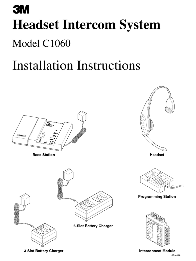
3M XT-1 User manual

3M Headset Intercom System Model XT-1
Installation Manual
Rev 1.0
© 3M 2007 November

3M Headset Intercom System Model XT-1 Installation Manual Rev 1.0 © 3M 2007 November
Page 2 of 54

Table of Contents
3M Headset Intercom System Model XT-1 Installation Manual Rev 1.0 © 3M 2007 November
Page 3 of 54
Table of Contents
Overview..................................................................................................................................... 5
Safety Information ................................................................................................................... 5
Other Conventions................................................................................................................... 6
FCC Information...................................................................................................................... 6
Installation.................................................................................................................................. 7
Overview of Installation ........................................................................................................... 7
Required Materials (Not Supplied) .......................................................................................... 7
Design the Installation............................................................................................................. 7
Install the Battery Charger.....................................................................................................10
Install the Order Point Speaker and Microphone Assemblies............................................... 11
Install the Vehicle Detector(s) ............................................................................................... 11
Install the Base Station.......................................................................................................... 11
Installing Accessory Boards in the Base Station................................................................... 23
Power Up............................................................................................................................... 27
Configuration ........................................................................................................................... 29
Enter Configuration Mode...................................................................................................... 29
Navigating the Base Station Display..................................................................................... 29
Connecting to the Ethernet Port............................................................................................ 31
Change Basic Volume Settings............................................................................................. 32
Change the Monitor Volume.................................................................................................. 33
Change the Night Volume ..................................................................................................... 35
Registering Headsets............................................................................................................35
Change Noise Reduction Level............................................................................................. 36
Set System Date and Time.................................................................................................... 37
Change Global Settings......................................................................................................... 37
Order Taking Modes Setup ................................................................................................... 40
Change Site Scheduling........................................................................................................ 40
Change Site Information........................................................................................................ 41
Change Self Monitoring......................................................................................................... 41
Change Passcodes ............................................................................................................... 42
Installer Setup........................................................................................................................ 42
Factory Setup (Restore Factory Defaults)............................................................................. 43
Create and Load Templates.................................................................................................. 43
Reboot System...................................................................................................................... 43
Check the Revision Levels.................................................................................................... 43
Activate the Backup Intercom................................................................................................ 44
Change the Microphone Preamp Gain.................................................................................. 44
Change Technical Service Contact Information.................................................................... 44
Troubleshooting ...................................................................................................................... 47
General Troubleshooting....................................................................................................... 47
Battery and Battery Charger Troubleshooting....................................................................... 48
Appendix: Base Station Specifications................................................................................. 49
Physical ................................................................................................................................. 49
Electrical................................................................................................................................ 49
Functional.............................................................................................................................. 49
Index.......................................................................................................................................... 51

Table of Contents
3M Headset Intercom System Model XT-1 Installation Manual Rev 1.0 © 3M 2007 November
Page 4 of 54

Overview
3M Headset Intercom System Model XT-1 Installation Manual Rev 1.0 © 3M 2007 November
Page 5 of 54
Overview
Safety Information
Safety Rules
Read, understand, and follow all safety information contained in these
instructions prior to installation & operation of the 3M Headset Intercom
System, Model XT-1. Failure to follow all instructions listed could result in
electrical shock, fire and/or other personal injury. Retain these instructions for
future reference.
Intended Use
The 3M Headset Intercom System Model XT-1 is intended for use to provide 2-
way radio-frequency audio communication in quick service drive-through
restaurants and convenience stores.
The system must be installed as specified in the Model XT-1 Installation
Instructions and operated as specified in Model XT-1 Operating Instructions in
quick service drive-through restaurants and convenience stores. It has not been
evaluated for other uses or locations.
Signal Words
Explanation of Signal Word Consequences
WARNING: Indicates a potentially hazardous situation, which, if
not avoided, could result in death or serious injury
and/or property damage.
CAUTION: Indicates a potentially hazardous situation, which, if
not avoided, may result in minor or moderate injury
and/or property damage.
CAUTION: Indicates a potentially hazardous situation, which, if
not avoided, may result in property damage.
Product Safety Labels
Explanation of Product Safety Labels
Attention: Read accompanying documentation
Warning: Risk of Electric Shock

Overview
3M Headset Intercom System Model XT-1 Installation Manual Rev 1.0 © 3M 2007 November
Page 6 of 54
System Warnings
WARNING
To reduce the risks associated with hazardous voltage:
•Disconnect power to the receptacle before installing or removing the
Base Station Power Supply. When removing receptacle cover screw,
cover may fall across plug pins or receptacle may become displaced.
Use only with duplex receptacle having center screw. Secure unit in
place by receptacle cover screw.
•If power supply is supplied with a grounding pin, connect directly to a
grounding receptacle – 3 prong.
To reduce the risks associated fire & property damage:
•Do not open, crush, expose to heat above 200 °F or incinerate the
battery.
•Always replace batteries, battery chargers and power supplies with
3M approved units acceptable for use in this system to avoid system
function & safety concerns.
CAUTION
To reduce the risks associated with environmental contamination due to
battery pack & to lead in the solder:
•Dispose of batteries, power supplies, battery charger and base
station in accordance with federal, state & local requirements. If
preferred, return these components to 3M Service Center for
disposal.
Other Conventions
Important Notes and Notes
Important Note:
It is strongly recommended that you pay attention to information inside of an
“Important Note:” box.
Note:
You may find information inside of a “Note:” box helpful.
FCC Information
Note:
This equipment has been tested and found to comply with the limits for a
Class A digital device, pursuant to part 15 of the FCC Rules. These limits are
designed to provide reasonable protection against harmful interference when
the equipment is operated in a commercial environment. This equipment
generates, uses, and can radiate radio frequency energy and, if not installed
and used in accordance with the instruction manual, may cause harmful
interference to radio communications. Operation of this equipment in a
residential area is likely to cause harmful interference in which case the user
will be required to correct the interference at his own expense.

Installation
3M Headset Intercom System Model XT-1 Installation Manual Rev 1.0 © 3M 2007 November
Page 7 of 54
Installation
Overview of Installation
Installation involves the following main steps:
1. Design the installation
2. Install the battery charger and begin charging the batteries.
3. Install the order point speaker and microphone assemblies.
4. Install the vehicle detector loop (s).
5. Install the base station(s).
6. Install accessory boards in the base station(s).
Required Materials (Not Supplied)
•Standard or surface-mount conduit (metal or plastic) to enclose all
system wiring.
•Assortment of sheet metal screws and wall anchors
•Sufficient 18 to 20 AWG, (1.02 to 0.81mm diameter) shielded twisted-
pair audio cable, sufficient in length to connect the speaker and
microphone assembly from the order point to the base station.
Important Note:
The twisted pair of wires for the microphone connection must be shielded for
proper operation. In duplex systems, microphone and speaker cannot be in
the same jacket unless specially designed for duplex such as 3M™ Cable part
number 78-8117-4313-3.
•Sufficient shielded twisted-pairs of audio cable to connect other
components such as grill monitor speaker, vehicle detection device, etc.
Design the Installation
There are multiple ways to install the intercom system. Before you begin you
must understand how many components you will be installing and where they
must be installed. Use the installation checklist (if available) and these
instructions to assist you in designing the system.

Installation
3M Headset Intercom System Model XT-1 Installation Manual Rev 1.0 © 3M 2007 November
Page 8 of 54
Determine the Drive Thru Type(s)
Following is a brief description of each drive thru type:
•A Single Drive Thru is the most common configuration. It is
comprised of one lane of traffic with one order point, and one or two
drive thru windows for payment and pick up.
Pick Up
Cash
Order Point
•A Tandem Drive Thru is comprised of a single lane of traffic with two
order points (one in front of the other) and one or two drive thru
windows for payment and pick up.
Pick Up
Cash
Order Point #1 Order Point #2

Installation
3M Headset Intercom System Model XT-1 Installation Manual Rev 1.0 © 3M 2007 November
Page 9 of 54
•A Side-by-Side Drive Thru, also known as a “Y” or “Merge” drive thru,
is comprised of two lanes of ordering traffic side-by-side, each with its
own ordering point, but merges into a single lane with one or two drive
thru windows for payment and pick up.
Pick Up
Cash
Order Point #2
Order Point #1
•A Dual Drive Thru is comprised of two completely separate drive thru
systems, each with its own lane, usually on opposite sides of the
building, its own order point, and one or two drive thru windows for
payment and pick up. The simplest dual drive thru is two single drive
thrus, but it is possible to have dual tandem, dual side-by-side, or even
a combination of different drive thru types.
Number and Configuration of Base Stations
Regardless of the drive thru type(s) there must be one base station for each order
point:
•Single drive thrus always have one base station.

Installation
3M Headset Intercom System Model XT-1 Installation Manual Rev 1.0 © 3M 2007 November
Page 10 of 54
•Tandem and side-by-side drive thrus always have two base stations,
and they must be wired together as a pair.
•Dual drive thrus typically have two base stations, but could have up to
four if they consist of one or two tandem or side-by-side drive thrus.
Number and Type of Vehicle Detectors
There can be several vehicle detectors for each base station.
•There is always one vehicle detector at the ordering point.
•There is usually a vehicle detector at each drive thru window.
•There are sometimes one or more vehicle detectors at other locations in
the parking lot to detect vehicles approaching the restaurant or drive
thru or to monitor parked vehicles waiting for an order.
There are two basic types of vehicle detector: presence and pulse.
•Presence detectors are more common. They tell the base station when a
vehicle is present over the detector. They remain active as long as the
vehicle stays within the range of detection.
•Pulse detectors are less common. They tell the base station when a
vehicle has arrived, but have no mechanism to know if or when the
vehicle leaves. An air hose is typically used to provide the pulse signal
when a vehicle rolls over it.
Install the Battery Charger
Perform the following steps to install and use the 6-slot or 3-slot battery charger.
1. Select a placement location:
•A flat, dry surface such as a desktop or shelf.
•An easy-to-reach wall location if you have the optional wall-
mount bracket.
•The power cord should be in place where it cannot be pinched
or bent
2. Install the wall-mount bracket on the wall, if applicable.
3. Place the charger on the wall-mount bracket or surface.
4. Connect the power supply transformer between the wall receptacle and
the charger. The charge indicator lights will flash.
Three-Slot Charger Six-Slot Charger
Power Supply Transformers

Installation
3M Headset Intercom System Model XT-1 Installation Manual Rev 1.0 © 3M 2007 November
Page 11 of 54
5. Insert each battery to be charged into a slot on the charger. The charge
indicator lights for each slot will light steadily red to indicate that the
battery is charging or green to indicate that the battery is fully charged.
6. When charging is complete, the batteries are ready for use.
Notes:
A fully discharged (dead) battery can take as long as 3 ½ hours to recharge.
Fully charged batteries should be stored whenever they are not in use.
Leaving them on the charger does not harm them or waste energy.
Install the Order Point Speaker and Microphone Assemblies
Use the recommended speaker and microphone systems listed below and follow
the included instructions:
•3M™ Microphone Assembly. Part # 78-6911-4935-1
•3M™ Speaker Assembly, Duplex, 5 inch. Part # 78-6911-4411-3
For information on wiring the speaker and microphone to the base station, see
“Base Station to Component Wiring,” page 17.
Install the Vehicle Detector(s)
Follow the instructions provided with the vehicle detectors for installing the
detector loop(s), speakers, and microphones.
For information on wiring and configuring the vehicle detector(s) to the base
station see “Base Station to Component Wiring,” page 17.
For information on installing the vehicle detector circuit boards in the base
station, see “Installing Accessory Boards in the Base Station” on page 23
Install the Base Station
Choose a Location
Generally, the base station should be located centrally, and close to the order
takers. However there are several important guidelines that must be followed to
reduce the risk of problems. Follow the guidelines to ensure that the base
station(s) can communicate with headsets in any foreseeable location:
•Do not assume that the location of an old base station is suitable for a
new base station.
•The bottom edge should be at least 5 ft (1.5 m) from the floor.
•The base station should be at least 3 ft (1 m) from large metallic
fixtures or appliances.
•The base station should be within 6 ft (2 m) of a 110VAC, 15A or 20A
electrical outlet.
•The base station whould be away from inside corners, airborne grease,
and moisture.
•Easily visible and the keypad accessible.
Pre-Testing the Location
Before you permanently mount the base station(s), one person can pre-test the
signal using the following procedure:
1. Temporarily mount the base station where you think it may have good
range.

Installation
3M Headset Intercom System Model XT-1 Installation Manual Rev 1.0 © 3M 2007 November
Page 12 of 54
2. Power the base station.
3. Register two headsets.
4. Change the order taking mode to Always On.
5. Put on two headsets.
6. Tap the talk button on one of the headsets.
7. Walk around the location, talking as you walk.
•If you can hear yourself in the other headset in all desirable
order-taker positions, the base station is in a suitable location.
•If you cannot hear yourself in the other headset in all desirable
order-taker positions, the base station should be move to a
different location.
Important Notes:
To ensure the best operating range for your system, locate the base station
where it is not within three feet of or blocked by large steel structures such as
doors, walls, or large appliances.
If you plan to use an outside order taker, be sure that the base station’s range
includes the outside order taker location.
If the best location you find is still unable to communicate to all areas, you
may need to install an external antenna.
Removing and Replacing the Cover
To remove the base station cover:
1. Disconnect power from the base station.
2. Loosen the two screws located at the bottom of the cover.
3. Lift the cover upward and away. The display and keypad remain with
the base, not with the cover.
To replace the base station cover:
1. Verify there are no obstructions (tools, etc.) in the way of the cover
being closed.
2. Align the top edge of the cover with the base.
3. Swing the bottom half of the cover down into place and gently push it
against the base until it locks into place. Tighten the two screws
located at the bottom of the cover.
Mount the Station
Perform the following procedure to install the base station.
1. Remove the base station cover, if necessary:
a. Loosen the two screws located at the bottom of the cover.
b. Lift the cover upward and away.

Installation
3M Headset Intercom System Model XT-1 Installation Manual Rev 1.0 © 3M 2007 November
Page 13 of 54
2. Attach the base station to the wall using the screws and anchors
supplied with the station. Depending upon the wall surface, you may
need to supply your own fasteners.
Note:
Steps 3 and 4 assume that all of the communication cabling has been prepared
and is available at the base station. If not, see “Base Station to Component
Wiring,” page 17.
3. Follow local best practices and any applicable regulations to route the
cables into the base station cabinet’s top, sides, or back (through the
wall) as neatly as possible. Do route power supply wiring with
communication wiring in the same conduit.
4. Attach all cables to their appropriate terminals.
5. Connect the base station transformer between the wall outlet and the
base station power supply connection.
Mounting
holes
Mounting
holes

Installation
3M Headset Intercom System Model XT-1 Installation Manual Rev 1.0 © 3M 2007 November
Page 14 of 54
Connect the Components
This section provides diagrams and information that should help you to properly
wire the system components together.
Note:
In all cases, you must have one base system for each order point (i.e., you
cannot run two or more order points from a single base station).
Base Station Wiring Terminal Identification
The following diagram identifies all of the wiring terminals and their labels.
The table that follows provides definitions of the labels and identifies where
they should be connected in the system.

Installation
3M Headset Intercom System Model XT-1 Installation Manual Rev 1.0 © 3M 2007 November
Page 15 of 54
Terminal Label Definition and Connection Information
12V IN Incoming power supply from the transformer
ORDER POINT: All of the wires on this terminal block go to the order point or monitor speaker
12V OUT 12 VDC power supply
EARTH Earth ground
MIC+ Positive phase microphone wire
MIC- Negative phase microphone wire
GND Microphone wire shielding
MEN SPKR+ Positive phase order point speaker
MEN SPKR- Negative phase order point speaker
MON SKR+ Positive phase monitor speaker
GRT_CN
GRT_CN

Installation
3M Headset Intercom System Model XT-1 Installation Manual Rev 1.0 © 3M 2007 November
Page 16 of 54
Terminal Label Definition and Connection Information
MON SKR- Negative phase monitor speaker
GRT_CNL Active low talk
BACKUP INTERCOM: All of the wires on this terminal block go to the backup intercom
MIC+ Positive phase microphone
MIC- Negative phase microphone
GND Microphone wire shielding
MEN SPKR+ Positive phase order point speaker
MEN SPKR- Negative phase order point speaker
MON SPKR+ Positive phase of monitor speaker
MON SPKR- Negative phase of monitor speaker
VEH_NO Vehicle detector (normally open)
VEH_COM If backup intercom includes external vehicle detector module, use this terminal
GRT CNCL IN If installation includes external greeter module or timer module and backup
intercom has an active low GRT_CNL output, use this terminal
INTERBASE_1: All wires on this terminal block go to INTERBASE_1 terminals on the interconnected base station
OUT- negative out (connects to negative in on interconnected base station)
OUT+ Positive out (connects to positive in on interconnected base station)
IN- Negative in (connects to negative out on interconnected base station)
IN+ Positive in (connects to positive out on interconnected base station)
INTERBASE_2: All wires on this terminal block go to INTERBASE_2 terminals on the interconnected base station
OUT- negative out (connects to negative in on interconnected base station)
OUT+ Positive out (connects to positive in on interconnected base station)
GND Ground
IN- Negative in (connects to negative out on interconnected base station)
IN+ Positive in (connects to positive out on interconnected base station)
GND Ground
UART_TX UART (transmit) connects to UART_RX on interconnected base station
UART_RX UART (receive) connects to UART_TX on interconnected base station
LAN Network connection (crossover cable to PC or patch cable to network)
PAGE Active low page
TALK Active low talk
GND Ground
SPLIT/CROSS Shorting this pin to GND will switch between Split Lane and Cross Lane modes
ORDER/TAKING Shorting this pin to GND will move through the order taking modes
DAY/NIGHT Shorting this pin to GND will switch between day and night modes
EXT_MSG Shorting this pin to GND will play a selected message (if optional greeter board
is installed)
VEH_APP Active low vehicle approaching
GND Ground
RELAY1_COM Relay 1 common

Installation
3M Headset Intercom System Model XT-1 Installation Manual Rev 1.0 © 3M 2007 November
Page 17 of 54
Terminal Label Definition and Connection Information
RELAY1_NO Connect to relay 1 if normally open relay
RELAY1_NC Connect to relay 1 if normally closed relay
RELAY2_COM Relay 2 common
RELAY2_NO Connect to relay 2 if normally open
RELAY2_NC Connect to relay 2 if normally closed
RELAY3_COM Relay 3 common
RELAY3_NO Connect to relay 3 if normally open
RELAY3_NC Connect to relay 3 if normally closed
EXT_AUDIO: All of the wires on this terminal block go to the external audio device
OUT- Negative out (connects to negative in on device)
OUT+ Positive out (connects to positive in on device)
GND Ground
IN- Negative in (connects to negative out on device)
IN+ Positive in (connects to positive in on device)
Base Station to Component Wiring
Good Wiring Practices
To reduce interference and improve signal quality, use the following practices
for all communication wiring:
•Keep shielding on the cable as close to the terminal as possible.
•Do not untwist pairs more than necessary.
•Do not allow cable strands to fray.
•Do not tin cable leads with solder.
•Fold uninsulated wire over onto itself before inserting into a terminal.
•Make sure screw terminals are tight.
A minimal, typical arrangement of the components is shown in the illustration
below:

Installation
3M Headset Intercom System Model XT-1 Installation Manual Rev 1.0 © 3M 2007 November
Page 18 of 54
The following diagram shows the wiring configuration between a base station
and the components of a single drive thru. In systems with two base stations,
use this wiring diagram for each of the stations, then see “Base Station to Base
Station Wiring,” Page 19.
Note:
Vehicle Detector 1 (VEHDET.1) must always be used for proper base station
operation. Vehicle detectors 2 and 3 (or any integral detectors installed with
optional modules) can be used at your discretion.

Installation
3M Headset Intercom System Model XT-1 Installation Manual Rev 1.0 © 3M 2007 November
Page 19 of 54
Base Station to Base Station Wiring
In any site with two base stations, the wiring between the two stations should be
completed as shown below:

Installation
3M Headset Intercom System Model XT-1 Installation Manual Rev 1.0 © 3M 2007 November
Page 20 of 54
Auxiliary Intercom
An auxiliary intercom is a wired communication system that can be used in the
event of base station failure. The wiring diagram below show where the
connections are made for a 3M model D15-D intercom. You can use a different
brand of intercom system, but the wire color coding will be different, so you will
have to determine how to wire the systems together by following the terminal
labels.
Other manuals for XT-1
9
Table of contents
Other 3M Intercom System manuals

3M
3M C860 User manual

3M
3M HEADSET C1060 User manual

3M
3M Peltor DECT-Com II User manual

3M
3M 478DA (D-15) User manual

3M
3M Convenience Store D-2400 User manual

3M
3M Performance Series User manual

3M
3M 478DA (D-15) User manual

3M
3M C960 Operating and installation instructions

3M
3M C1025 User manual

3M
3M Convenience Store C5000 User manual

3M
3M HEADSET C1060 Application guide

3M
3M C960SL User manual

3M
3M Audio Greeter A300 User manual

3M
3M HEADSET C1060 User manual

3M
3M C860 Operating and installation instructions

3M
3M 478DA D-15 User manual

3M
3M Signature Series User manual

3M
3M D-2475 User manual

3M
3M C960 Quick start guide

3M
3M C860 User manual