manuals.online logo
Brands
  1. Home
  2. •
  3. Brands
  4. •
  5. 3One data
  6. •
  7. Network Router
  8. •
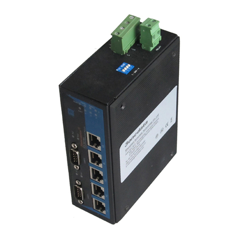
  9. 3One data IES318 Series User manual

3One data IES318 Series User manual

IES318 series
Unmanaged Industrial Ethernet
Switch Quick Installation Guide
3onedata Co., Ltd.
Address: 3/B, Zone 1, Baiwangxin High Technology
Industrial Park, Xili, Nanshan District, Shenzhen
Website: www.3onedata.com
Tel: +86 0755-26702688
Fax: +86 0755-26703485
Package Checklist
Please check the integrity of package and accessories while
first using the switch.
1. Industrial Ethernet switch ⅹ1 (with wiring terminal block)
2. Manual 3. DIN-Rail mounting attachment
4. Certification 5. Warranty card
If any of these items are damaged or lost, please contact our
company or dealers, we will solve it asap.
Product Overview
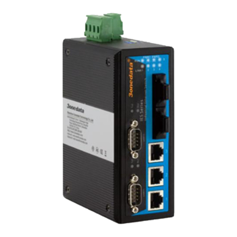
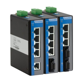
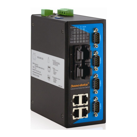
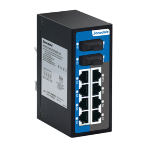
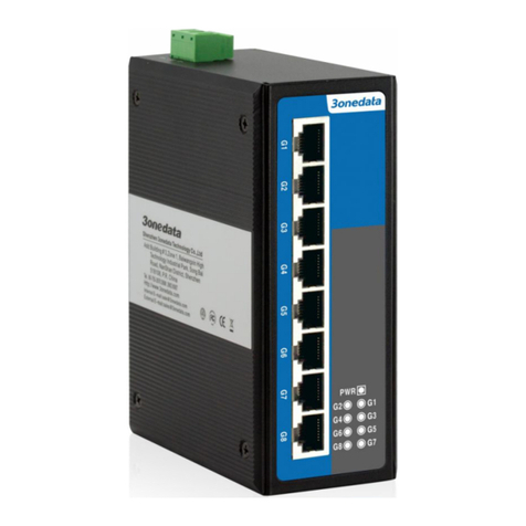
The series products are unmanaged industrial Ethernet
switches, including the following models:
Model I IES318 (8 ports)
Model II IES318-1F (7 ports + 1 fiber port)
Model III IES318-2F (6 ports + 2 fiber ports)
Panel design
Rear view, Bottom view and Top view
Front view
Model I Model II Model III
1. DIN-Rail mounting kit
2. 4-pin terminal block for power input
3. Grounding screw
4. Relay interface
5. Console port
6. DIP switch
7. Running status indicator
8. Alarm indicator
9. Power supply indicator
10. 100Base-TX connection status indicator
11. 100Base-TX
12. 100Base-FX connection status indicator
13. 100Base-FX
Mounting Dimension
Unit (mm)
DIN-Rail Mounting
For convenient usage in industrial environments, the product
adopts 35mm DIN-Rail mounting, mounting steps as below:
Step 1 Check if the DIN-Rail mounting kit is installed firmly.
Step 2 Insert the bottom of DIN-Rail mounting kit (one side
with spring support) into DIN-Rail, and then insert
the top into DIN-Rail.
Tips:
Insert a little to the bottom, lift upward and then
insert to the top.
Step 3 Check and confirm the product is firmly installed on
DIN-Rail, then mounting ends.
Disassembling DIN-Rail
Step 1 Device power off.
Step 2 After lift the device upward slightly, first shift out the
top of DIN-Rail mounting kit, then shift out the
bottom of DIN-Rail, disassembling ends.
Note:
1. Don't place or install the device in area near water or
moist, keep the relative humidity of the device
surrounding between 5%~95% without condensation.
2. Before power on, first confirm the supported power
supply specification to avoid over-voltage damaging the
device.
3. The device surface temperature is high after running;
please don't directly contact to avoid scalding.
Power Supply Connection
DC power supply
The series devices provide 4 bits power
supply input terminal blocks and two
independent DC power supply systems
for PWR1 and PWR2. The power supply
has nonpolarity and anti-reverse
functions, it can normally operate after reverse connection.
Power supply range: 12~48VDC
Note:
1. Power ON operation: First insert the power supply
terminal block into the device power supply interface,
and then plug the power supply plug contact and power
on.
2. Power OFF operation: first unpin the power plug, then
remove the terminal block wiring part, please note the
operation order above.
Relay Connection
Relay terminals are a pair of normally open
contacts in device alarm relay. They are open
circuit in normal non alarm state, closed when
any alarm information occurs. E.g. it's closed
when power off, and send out alarm. This series switches
support 1 channel relay alarm information output, support
network abnormal alarm output, it can be connected to
alerting lamp, alarm buzzer, or other switching value
collecting devices for timely warning operating staffs when
alarm information occurs.
DIP Switch Setting
Provide 4-bits DIP switch for function setting,
where "ON" is enable valid terminal. Changing
the status of DIP switch doesn't need power off
and power on again.
DIP switch define as follow:
1. Flow control 2. Force 10M (RJ45)
3. Port alarm 4. Reserved
Checking LED Indicator
LED indictor monitors the operating status to
comprehensively simplify the fault solution. The function of
each LED is described in the table as below:
LED
State
Description
PWR1
ON
PWR1 is connected and running
normally
OFF
PWR1 is disconnected and
running abnormally
PWR2
ON
PWR2 is connected and running
normally
OFF
PWR2 is disconnected and
running abnormally
ALM
ON
Port link alarm
OFF
Port link without alarm
RUN
ON/OFF
Device abnormal
Blinking
Device is running well
Link/ACT
ON
Port connection is active
Blinking
Data transmitted
OFF
Port connection is not active
Specification
Panel
100Base-FX
100Base-FX, interface SC/ST/FC
optional
100Base-TX
10/100Base-T(X) self-adapting RJ45
port, half/full duplex self-adapting or
compulsive working mode, support
MDI/MDI-X self-adapting
Console port
Reserved
Alarm
interface
2-core 7.62mm pitch terminal block,
support 1 relay alarm output
Indicator
Power indicator, run indicator, interface
indicator, alarm indicator
Exchange attributes
Backplane
bandwidth
1.6G
Packet buffer
size
1Mbit
MAC table
size
2K
Power supply
Input power
supply
DC power supply series products 12 ~
48VDC
support redundant double power
supply, nonpolarity
Access
terminal
4-core 7.62mm pitch terminal blocks
Consumption
IES318
No-load consumption: 1.3W@48VDC
Full-load consumption: 3.6W@48VDC
IES318-1F
No-load consumption: 3.2W@48VDC
Full-load consumption: 4.5W@48VDC
IES318-2F
No-load consumption: 4.5W@48VDC
Full-load consumption: 8.5W@48VDC
Working environment
Temperature
Working temperature:-40℃~75℃
Storage temperature: -40℃~85℃
Working
humidity
5%~95% (no condensation)
Protection
grade
IP40 (metal shell)

This manual suits for next models

3

Other 3One data Network Router manuals

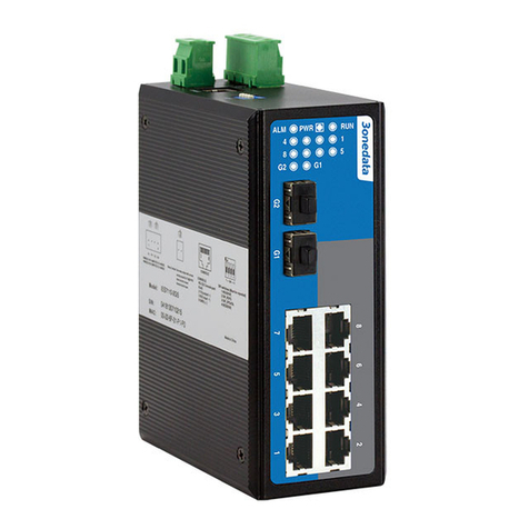
3One data IES7110-2GS-P User manual

3One data

3One data IES7110-2GS-P User manual

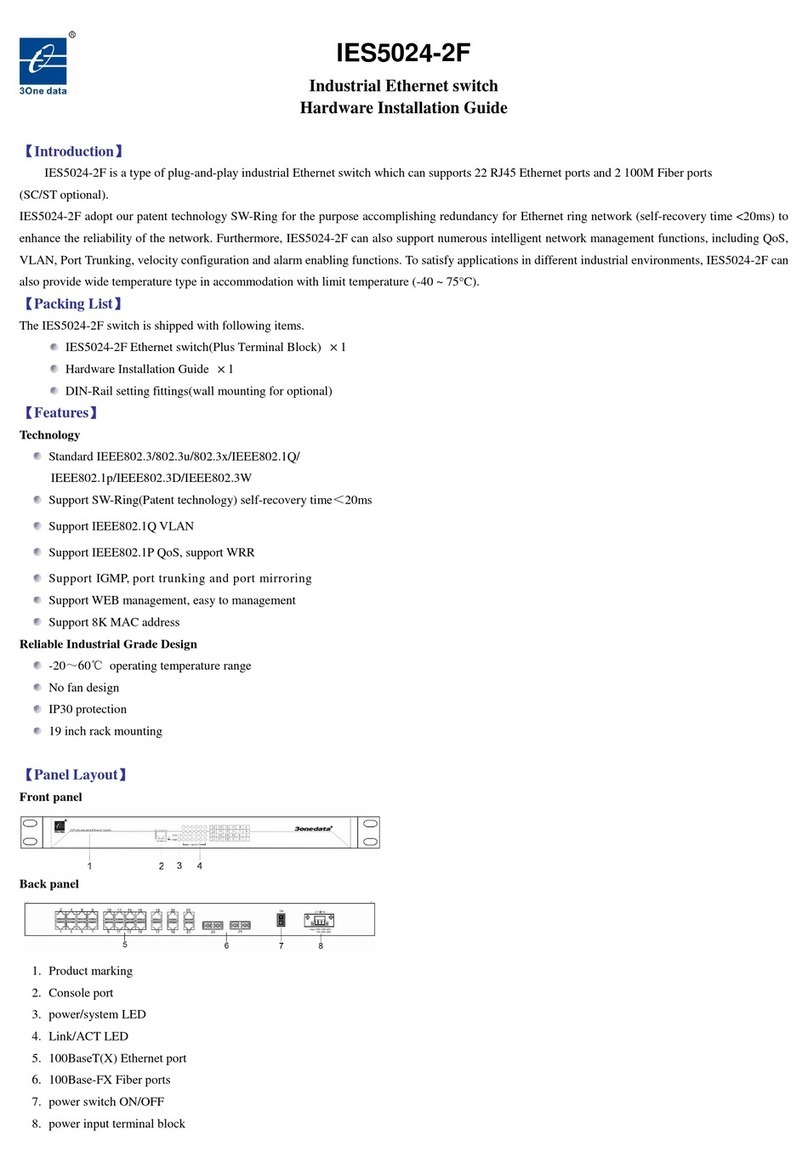
3One data IES5024-2F Manual

3One data

3One data IES5024-2F Manual

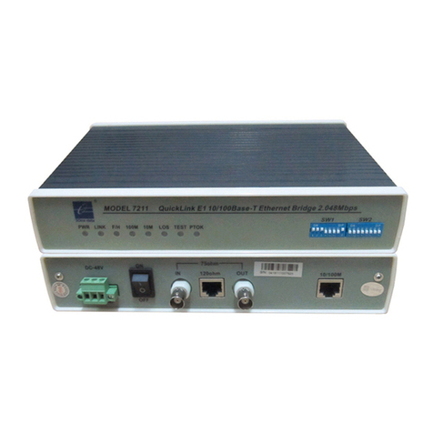
3One data 7211 User manual

3One data

3One data 7211 User manual

3One data 7212 User manual

3One data

3One data 7212 User manual

3One data PS1005G-1GT-4PoE User manual

3One data

3One data PS1005G-1GT-4PoE User manual

3One data IES605-2D series User manual

3One data

3One data IES605-2D series User manual

3One data ICS5028G-4XGS-8GC User manual

3One data

3One data ICS5028G-4XGS-8GC User manual

3One data IES2010-2GS-4F Manual

3One data

3One data IES2010-2GS-4F Manual

3One data IES618-P User manual

3One data

3One data IES618-P User manual

3One data IES3016G User manual

3One data

3One data IES3016G User manual

3One data IES5028G-8GC-4GS User manual

3One data

3One data IES5028G-8GC-4GS User manual

3One data IES308-1F-P User manual

3One data

3One data IES308-1F-P User manual

3One data IES6312 Series User manual

3One data

3One data IES6312 Series User manual

3One data IES6116 Series User manual

3One data

3One data IES6116 Series User manual

3One data IES7110 Series User manual

3One data

3One data IES7110 Series User manual

3One data MES600 Series User manual

3One data

3One data MES600 Series User manual

3One data IES7120G-4GS User manual

3One data

3One data IES7120G-4GS User manual

3One data IES6116 Series User manual

3One data

3One data IES6116 Series User manual

3One data IES6116-2F-P User manual

3One data

3One data IES6116-2F-P User manual

3One data IEM615 Series Instructions for use

3One data

3One data IEM615 Series Instructions for use

3One data IRT5300-AW-5T2D User manual

3One data

3One data IRT5300-AW-5T2D User manual

3One data IES308 Manual

3One data

3One data IES308 Manual

3One data ES208G User manual

3One data

3One data ES208G User manual

3One data IES215-1F-P User manual

3One data

3One data IES215-1F-P User manual

Popular Network Router manuals by other brands

Atel V810VD quick start guide

Atel

Atel V810VD quick start guide

EuroLite DMX LED Operator 4 user manual

EuroLite

EuroLite DMX LED Operator 4 user manual

Pentagram Cerberus Wi-Fi Lite Installation and user manual

Pentagram

Pentagram Cerberus Wi-Fi Lite Installation and user manual

Siemens SIMATIC NET SCALANCE W760 operating instructions

Siemens

Siemens SIMATIC NET SCALANCE W760 operating instructions

Beamz 154.092 instruction manual

Beamz

Beamz 154.092 instruction manual

AEM SM10 Installation and operation manual

AEM

AEM SM10 Installation and operation manual

Beam GE-PON ONT C504W installation guide

Beam

Beam GE-PON ONT C504W installation guide

Avaya 8300 Series Installation

Avaya

Avaya 8300 Series Installation

NETGEAR Orbi Pro WiFi 6 AX6000 user manual

NETGEAR

NETGEAR Orbi Pro WiFi 6 AX6000 user manual

InHand IR302 Quick installation manual

InHand

InHand IR302 Quick installation manual

McDATA ULTRANETTM EDGE STORAGE ROUTER 3000 user guide

McDATA

McDATA ULTRANETTM EDGE STORAGE ROUTER 3000 user guide

B+B SMARTWORK SmartFlex SR305 user manual

B+B SMARTWORK

B+B SMARTWORK SmartFlex SR305 user manual

virtual access GW3330 user manual

virtual access

virtual access GW3330 user manual

IP-COM M50 user manual

IP-COM

IP-COM M50 user manual

NETGEAR Nighthawk R7200 user manual

NETGEAR

NETGEAR Nighthawk R7200 user manual

D-Link DIR-636L Quick install guide

D-Link

D-Link DIR-636L Quick install guide

3M Volition VOL-1081 user guide

3M

3M Volition VOL-1081 user guide

VADDIO CCU Image Controller manual

VADDIO

VADDIO CCU Image Controller manual

manuals.online logo
manuals.online logoBrands
  • About & Mission
  • Contact us
  • Privacy Policy
  • Terms and Conditions

Copyright 2025 Manuals.Online. All Rights Reserved.