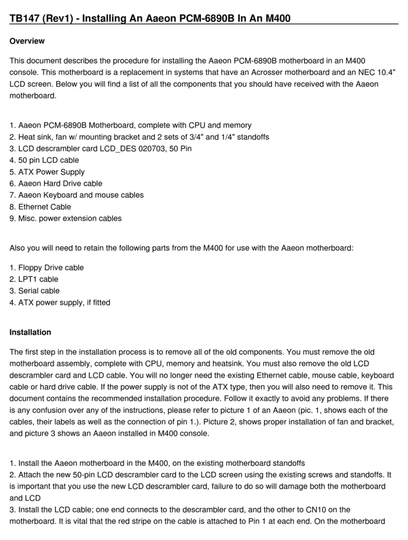
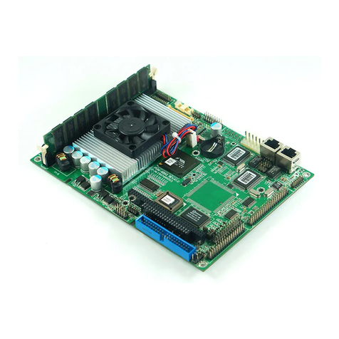
Aaeon FSB-960H User manual

Full-size SBC FSB-960H
FSB-960H
Intel
® CoreTM 2 Duo
LGA 775 Processor
Full-size CPU Card
With DDRII, Ethernet,
IDE/ PCI/ PCI-Express
FSB-960H Manual Rev.A 2nd Ed.
Mar. 2008

Full-size CPU Card FSB-960H
i
Copyright Notice
This document is copyrighted, 2008. All rights are reserved. The
original manufacturer reserves the right to make improvements to
the products described in this manual at any time without notice.
No part of this manual may be reproduced, copied, translated, or
transmitted in any form or by any means without the prior written
permission of the original manufacturer. Information provided in this
manual is intended to be accurate and reliable. However, the
original manufacturer assumes no responsibility for its use, or for
any infringements upon the rights of third parties that may result
from its use.
The material in this document is for product information only and is
subject to change without notice. While reasonable efforts have
been made in the preparation of this document to assure its
accuracy, AAEON assumes no liabilities resulting from errors or
omissions in this document, or from the use of the information
contained herein.
AAEON reserves the right to make changes in the product design
without notice to its users.

Full-size CPU Card FSB-960H
ii
Acknowledgments
All other products’ name or trademarks are properties of their
respective owners.
Award is a trademark of Award Software International, Inc.
CompactFlash™is a trademark of the Compact Flash
Association.
Intel®, Core™2 Duo are trademarks of Intel®Corporation.
Microsoft Windows®is a registered trademark of Microsoft Corp.
ITE is a trademark of Integrated Technology Express, Inc.
IBM, PC/AT, PS/2, and VGA are trademarks of International
Business Machines Corporation.
SoundBlaster is a trademark of Creative Labs, Inc.
Please be notified that all other products’ name or trademarks
not be mentioned above are properties of their respective
owners.

Full-size CPU Card FSB-960H
iii
Packing List
Before you begin installing your card, please make sure that the
following materials have been shipped:
1709070800 SATA Cable
1701340704 Flat Cable
1701400453 ATA-100 Cable
1700060192 Keyboard and Mouse Cable
1701260307 Flat Cable
1701100305 Flat Cable with bracket
1709100201 USB Cable w/ Bracket
Quick Installation Guide
CD-ROM for manual (in PDF format) and drivers
FSB-960H CPU Card
If any of these items should be missing or damaged, please
contact your distributor or sales representative immediately.

Full-size CPU Card FSB-960H
iv
Contents
Chapter 1 General Information
1.1 Introduction................................................................1-2
1.2 Feature......................................................................1-3
1.3 Specification..............................................................1-4
Chapter 2 Quick Installation Guide
2.1 Safety Precautions....................................................2-2
2.2 Location of Connectors and Jumpers .......................2-3
2.3 Mechanical Drawing..................................................2-4
2.4 List of Jumpers..........................................................2-5
2.5 List of Connectors .....................................................2-6
2.6 Setting Jumpers ........................................................2-8
2.7 Clear CMOS (JP1) ....................................................2-9
2.8 TPM Selection (JP2) .................................................2-9
2.9 MFG Selection (JP4).................................................2-9
2.10 BIOS Boot Device (JP8)..........................................2-9
2.11 Front Panel Connector (FP1)..................................2-9
2.12 Front Panel Connector (FP2)..................................2-10
2.13 RS-232 Serial Port Connector (COM1)...................2-10
2.14 RS-232/422/485 Serial Port Connector (COM2).....2-10
2.15 IrDA Connector (IR1)...............................................2-10
2.16 LPT Port Connector (LPT1) ....................................2-11
2.17 USB Connector (USB1~3) ......................................2-11
Full-size CPU Card FSB-960H
v
2.18 Fan Connector (FAN1, CPUFAN1).........................2-12
2.19 PS2 Keyboard/Mouse Connector (KM1).................2-12
2.20 LAN LED Connector (CN1~2).................................2-12
2.21 HDA Connector (CN3).............................................2-12
2.22 Internal Keyboard Connector (CN4)........................2-13
Chapter 3 Award BIOS Setup
3.1 System Test and Initialization. ..................................3-2
3.2 Award BIOS Setup....................................................3-3
Chapter 4 Driver Installation
4.1 Installation.................................................................4-3
Appendix A Programming The Watchdog Timer
A.1 Programming .........................................................A-2
A.2 W83627EHG Watchdog Timer Initial Program......A-6
Appendix B I/O Information
B.1 I/O Address Map.................................................. B-2
B.2 1st MB Memory Address Map ................................B-3
B.3 IRQ Mapping Chart................................................B-4
B.4 DMA Channel Assignments...................................B-5

Full-size SBC FSB-960H
Chapter 1 General Information 1-1
General
Chapter
1
Information

Full-size SBC FSB-960H
Chapter 1 General Information 1-2
1.1 Introduction
AAEON, a leading Industrial PC manufacturer, announces the
debut of a high performance full-size Single Board Computer, the
FSB-960H. AAEON has developed this full-size SBC based on the
latest Intel®Q35 Express chipset and the Intel®Core™2 Duo
processor, to fulfill the increasing demands of multi-core
processing.
The FSB-960H adopts Intel’s dual-core processor at current speeds
up to 2.13 GHz with 1066MHz FSB to meet a wide range of
performance requirements. In a PICMG 1.3 SHB Express form
factor the FSB-960H system host board takes full advantage of the
Intel®Q35 Express chipset for enhanced system performance and
generous expansion capabilities. Considerable bandwidth is
available with point-to-point serial PCI Express via [x16]and[x4]
interfaces. Maximizing the available PCI Express channels offers
the greatest flexibility to today’s demanding I/O requirements. Two
DIMM slots of dual channel DDR II 800 RAM provide ample
memory bus bandwidth for demanding applications. The
FSB-960H has been designed for users that require high
performance and reliability for critical applications.

Full-size SBC FSB-960H
Chapter 1 General Information 1-3
1.2 Features
Intel CoreTM 2 Duo/ Wolfdale LGA775 CPU up to
2.13GHz, FSB 800/1066/1333MHz
DDR II 667/800 Memory Support Up to 4GB
Integrated Intel Enhanced Graphics Core, VGASupport
10/100/1000Base-TX Ethernet x 2 (10/100 & GbE
Optional)
PCI-Express[x16]x1 and PCI-Express[x4]x1 Link to
Backplane
USB2.0 x 11/ RS-232/422/485 x 1/ RS-232 x 1/ Parallel x
1/ IrDA Port x 1
SATA II Port x 2 (RAID), CompactFlash Type II
Compliance with PICMG 1.3
Intel AMT with Circuit Breaker

Full-size SBC FSB-960H
Chapter 1 General Information 1-4
1.3 Specification
System
CPU: Supports Intel®Core 2 Duo/
Wolfdale LGA775 Processor
up to 2.13GHz (FSB
800/1066/1333MHz)
Chipset: Intel®Q35 + Intel®ICH9R
(ICH9DO)
System Memory: 240-pin 1.8V DDRII DIMM
Socket x 2, total up to 4GB
Support Dual-Channel
DDRII 667/800 Memory
VGA Controller: Enhanced Integrated
Graphics
Ethernet: PCI-Express x 1 10/100Mb
or 10/100/1000Mb LAN
optional, RJ-45 Connector x
2, Intel 82566X/ 82562V/
82573V/E Controller
BIOS: Award Plug & Play SPI
BIOS – 16Mb ROM
Audio (Daughter board):Audio Codec, MIC-in/
Line-in/ Line-out/ CD-in
IDE Interface: IDE Slot x 1 (SATA to IDE)

Full-size SBC FSB-960H
Chapter 1 General Information 1-5
Expansion Interface: PCI x 3/ PCI-Express[x4]x
1 / PCI-Express[x16]
Connector x 1
SSD: Supports CompactFlash™
type II connector x 1
IR Interface: Supports IrDA header x 1
Universal Serial Bus: USB 2.0 Port on CPU Card
x 7; 5x2 pin header for
internal x 3; Type-A
connector onboard x 1;
USB2.0 Port to Backplane x
4
Watchdog Timer: 1~255 Step, can be set with
software on Super I/O
RTC: Internal RTC
Power Supply Voltage: ATX, ATX +12V
Battery: Lithium battery
Power Requirement: ATX12V connector, other
from backplanes
Board Size: 13.3” (L) x 4.98” (W)
(3338.58mm x 126.39mm)
Operation Temp.: 32°F~140°F (0°C ~60°C)
Display
VGA Controller: Enhanced Integrated
Graphics

Full-size SBC FSB-960H
Chapter 1 General Information 1-6
Memory: Shared memory up to 256M
Resolutions: Up to 1920 x 1200 @85MNz
for CRT; Up to 1600 x 1200
@60MHz for LCD
I/O
FDD Interface: Standard FDD port x 1
(supports up to 1 floppy
device)
Serial Port: Two COM ports: (Internal
pin header x 2)
COM 1: RS-232
COM 2: RS-232/422/485
Parallel Port: Supports SPP/EPP/ECP
mode
Keyboard & Mouse connector:
Mini-DIN for PS/2 Keyboard
and mouse connector x 1;
Internal keyboard pin
header x 1

Full-size SBC FSB-960H
Chapter 2 Quick Installation Guide 2-1
Quick
Installation
Chapter
2
Guide
Notice:
The Quick Installation Guide is derive
d
f
rom Chapter 2 of user manual. For othe
r
chapters and further installation
instructions, please refer to the use
r
manual CD-ROM that came with th
e
p
roduct.
Part No. 2007960H11 Printed in Taiwan MAR. 2008

Full-size SBC FSB-960H
Chapter 2 Quick Installation Guide 2 - 2
2.1 Safety Precautions
Always completely disconnect the power cord
from your board whenever you are working on
it. Do not make connections while the power is
on, because a sudden rush of power can
damage sensitive electronic components.
Always ground yourself to remove any static
charge before touching the board. Modern
electronic devices are very sensitive to static
electric charges. Use a grounding wrist strap at
all times. Place all electronic components on a
static-dissipative surface or in a static-shielded
bag when they are not in the chassis

Full-size SBC FSB-960H
Chapter2QuickInstallationGuide2 - 3
2.2 Location of Connectors and Jumpers

Full-size SBC FSB-960H
Chapter 2 Quick Installation Guide 2 - 4
2.3 Mechanical Drawing

Full-size SBC FSB-960H
Chapter2QuickInstallationGuide2 - 5
2.4 List of Jumpers
The board has a number of jumpers that allow you to configure your
system to suit your application.
The table below shows the function of each of the board's jumpers:
Jumpers
Label Function
JP1 Intruder
JP2 TPM
JP4 MFG
JP7 Clear CMOS
JP8 BIOS Boot Device
JP9 Reset Select For Future

Full-size SBC FSB-960H
Chapter 2 Quick Installation Guide 2 - 6
2.5 List of Connectors
The board has a number of connectors that allow you to configure
your system to suit your application. The table below shows the
function of each board's connectors:
Label Function
FP1 Front Panel Connector 1
FP2 Front Panel Connector 2
ATX2 ATX Power_12V Connector
VGA1 VGA Display Connector
FDD1 Floppy Connector
IDE1 EIDE Connector
Note: Supports one IDE device only (master).
SATA1~4 Serial ATA Connector
CFD1 Compact Flash Slot
COM1 RS-232 Serial Port Connector
COM2 RS-232/422/485 Serial Port Connector
IR1 IrDA Connector
LPT1 LPT Port Connector
USB1~3 USB Connector
USB4 USB Connector
LAN1 10/100 or 100/1000 Base-TX Ethernet
Connector
LAN2 10/100/1000 Base-TX Ethernet Connector
DIMM1~2 DDR2 DIMM Slot
FAN1 Fan Connector
CPUFAN1 Fan Connector
KM1 PS2 Keyboard/Mouse Connector

Full-size SBC FSB-960H
Chapter2QuickInstallationGuide2 - 7
CN1 LAN 1 Active LED Connector
CN2 LAN 2 Active LED Connector
CN3 HDA Connector
CN4 Internal Keyboard Connector

Full-size SBC FSB-960H
Chapter 2 Quick Installation Guide 2 - 8
2.6 Setting Jumpers
You configure your card to match the needs of your application by
setting jumpers. A jumper is the simplest kind of electric switch. It
consists of two metal pins and a small metal clip (often protected by
a plastic cover) that slides over the pins to connect them. To “close”
a jumper you connect the pins with the clip.
To “open” a jumper you remove the clip. Sometimes a jumper will
have three pins, labeled 1, 2 and 3. In this case you would connect
either pins 1 and 2 or 2 and 3.
123
Open Closed Closed 2-3
A pair of needle-nose pliers may be helpful when working with
jumpers.
If you have any doubts about the best hardware configuration for
your application, contact your local distributor or sales
representative before you make any change.
Generally, you simply need a standard cable to make most
connections.
Table of contents
Other Aaeon Motherboard manuals

Aaeon
Aaeon UP Xtreme User manual

Aaeon
Aaeon PCM-6893 Instruction Manual

Aaeon
Aaeon PCM-6897/L User manual

Aaeon
Aaeon PCM-6890 User manual

Aaeon
Aaeon PCM-6892 Rev.B User manual

Aaeon
Aaeon EMB-Q170B User manual

Aaeon
Aaeon PCM-LN05 Rev.B User manual

Aaeon
Aaeon All-in-One Super7 Single Board Computer... User manual

Aaeon
Aaeon IMBM-H110A User manual

Aaeon
Aaeon SBC-558P User manual

Aaeon
Aaeon HSB-910I User manual

Aaeon
Aaeon Gene-6320 User manual

Aaeon
Aaeon HSB-835P User manual

Aaeon
Aaeon EMB-BSW1 User manual

Aaeon
Aaeon SBC-558 User manual

Aaeon
Aaeon PCM-5896 User manual

Aaeon
Aaeon PCM-5893L User manual

Aaeon
Aaeon EMB-APL1-A10-3350-F1-LV User manual

Aaeon
Aaeon PCM-8120 User manual

Aaeon
Aaeon PICO-APL1 User manual