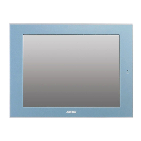
Aaeon AMB-2003 Series User manual

AMB-2003 Series
Modular System Industrial Panel PCs
Version 2.2for SBC-658
Industrial Panel PCs
Industrial Panel PCs for Industrial Automation
User’s Manual

Safety & Warranty
1. Read these safety instructions carefully.
2. Keep this user's manual for later reference.
3. Disconnect this equipment from any AC outlet before cleaning. Do not use
liquid or spray detergents for cleaning. Use a damp cloth.
4. For pluggable equipment, the power outlet must be installed near the
equipment and must be easily accessible.
5. Keep this equipment away from humidity.
6. Put this equipment on a reliable surface during installation. Dropping it or
letting it fall could cause damage.
7. The openings on the enclosure are for air convection. Protect the equipment
from overheating. DO NOT COVER THE OPENINGS.
8. Make sure the voltage of the power source is correct before connecting the
equipment to the power outlet.
9. Position the power cord so that people cannot step on it. Do not place
anything over the power cord.
10. All cautions and warnings on the equipment should be noted.
11. If the equipment is not used for a long time, disconnect it from the power
source to avoid damage by transient over-voltage.
12. Never pour any liquid into an opening. This could cause fire or electrical
shock.
13. Never open the equipment. For safety reasons, only qualified service
personnel should open the equipment.
14. If any of the following situations arises, get the equipment checked by
service personnel:
a. The power cord or plug is damaged.
b. Liquid has penetrated into the equipment.
c. The equipment has been exposed to moisture.
d. The equipment does not work well, or you cannot get it to work
according to the users manual.
e. The equipment has been dropped and damaged.
f. The equipment has obvious signs of breakage.
15. DO NOT LEAVE THIS EQUIPMENT IN AN UNCONTROLLED
ENVIRONMENT WHERE THE STORAGE TEMPERATURE IS
BELOW -20° C (-4°F) OR ABOVE 60° C (140° F). IT MAY DAMAGE
THE EQUIPMENT.
Caution:
Dangerofexplosionifbattery is incorrectlyreplaced.Replace only withthesame or equivalenttype
recommended by the manufacturer. Dispose of used batteries according to the manufacturer’s
instructions.
FCC Safety
This device complies with Part 15 FCC Rules. Operation is subject to the
following two conditions: (1) this device may not
cause harmful interference, and (2) this device must
accept any interference received including
interference that may cause undesired operation.

Contents
Chapter1 General Information.........................................5
1.1 Introduction.................................................... 6
1.2 Specifications ..................................................7
General ................................................................................7
Environmental......................................................................7
Power Supply Selection Table.............................................7
Features ...............................................................................8
Specifications ......................................................................9
1.3 Touchscreen (Optional)..................................9
1.4 LCD Specifications....................................... 10
1.5 Dimensions.................................................... 11
1.6 Panel Mounting............................................. 12
1.7 Packing List .................................................. 13
Chapter2 Installation.......................................................14
Chapter3Award BIOS Setup..........................................51

1
Chapter1 General Information
1.1 Introduction.....................................................6
1.2 Specifications...................................................7
1.3 Touchscreen (Optional) ..................................9
1.4 LCD Specifications........................................10
1.5 Dimensions.....................................................11
1.6 Panel Mounting.............................................12
1.7 Packing List...................................................13

1.1 Introduction
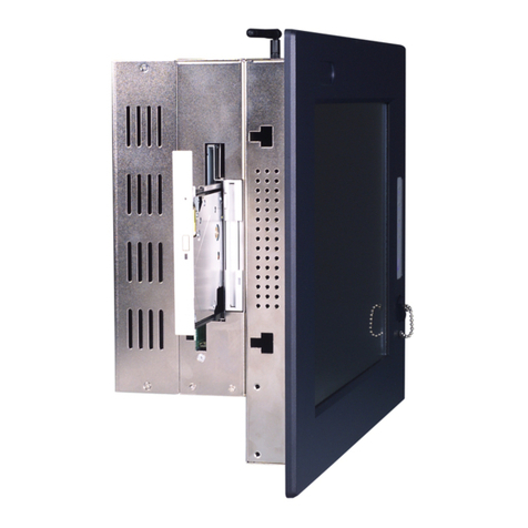
The AMB-2003 series modular system panel PCs, is the PC-base
industrial computer thatspecially designed to keep normal operation under
harsh environment, which meet the entire requirement as an industrial man
machine interface (MMI).
They provide a complete hard ware application and construct a high
quality plastic front panel which meets the toughest industrial and
environmental protection standards
It is afull-function PC-base system with a 10.4” VGA (640 x 480) color
TFT hi-brightness, long-life time LCD display, and compact with different
control modules via a 50-pin cable. The compact dimensions are ideal for
automation applications when the installation space is critical.
These PCs are characterized by their space saving, there are two free slots
for PCI/ ISA. AMB-2003 is heavy-duty steel chassis with a sealed plastic
front panel meets the toughest industrial and environmental standards. All
the controls and connectors are placed on the rear panel; you can connect
the panel PCs to other devices via them.

1.2 Specifications
General
nConstruction:Heavy-duty aluminum chassis & plastic or
aluminum front panel
nDisk drive housing:
a 3.5" HDD ora 2.5”HDD, Slim CD-ROM
& Slim FDD.
nDimensions(AMB-2003): 330(W) x 252(H) x 128mm(D)
nGross Weight: 9.6Kg
Environmental
nOperating temperature:0° to 50°
nStorage temperature: -20° to 60°
nRelative humidity: 5 to 95%, non-condensing
nAltitude: 10,000 ft. (3000 meters)
nVibration:
5 to 17Hz, 0.1" double-amplitude displacement
17 to 500 Hz, 1.5G peak to peak
nShock: 10G-peak acceleration (11-msec. duration)
nEMI: FCC/CE Class A
Power Supply Selection Table
Mode Input voltage
Universal/70W 85-270VAC
24VDC/70W 10-30VDC

Features
AMB-2003 (10.4”LCD + ACS-2303 Control Box)
n10.4” VGA color TFT LCD display
nPlastic front panel and heavy-duty steel chassis
nSupports Socket 370 CPU up to Pentium III
850MHz
nDisk Drive Space for CD-ROM, FDD and HDD
nSupports DiskOnChip and DiskOnModule
nTwo free expansion slotsfor ISA or PCI
nResistive touchscreen (optional)
nRotatable mounting mechanism (optional)
***Expansion IDE port will not functional when both HDD & CD-ROM
install in the machine

Specifications
AMB-2003 (10.4”LCD + ACS2303 Control Box)
nConstruction: Heavy-duty steel chassis &
plastic front panel.
nCPU: Up to Intel Celeron/ P III 850MHz
nMemory: Supports up to 128MB
nDisplay: 10.4”VGA (640 x 480) TFT color LCD
nLCD/CRT controller:
NS Cx5530 Chipset
UMA supports up to 2.5MB display memory
nNetwork (LAN):
Intel 8139B 10/100 Base-T Ethernet controller
nI/O ports:
COM1: RS-232
COM2: RS-232 or RS-422/485(jumper select)
1 parallel port (support ECP/EPP)
1 PS/2 keyboard interface
1 PS/2 mouse interface
nDisk Drive Housing:
3.5”HDD or
2.5”HDD and Slim FDD or
2.5”HDD and Slim CD-ROM
nUSB connector: Dual USB ports
nMounting: Panel mount, Handle mount
nPower supply: Universal 70W switching power
supply
nOS support: MS DOS, Windows 98/SE,
Windows NT4.0, Windows 2000.
1.3 Touchscreen (Optional)
lType: 8-wire, analog resistive
lResolution: 1024 x 1024
lLight transmission: 76%±2
lController: RS-232 interface

1.4 LCD Specifications
Model AMB-2003
Display type TFT color LCD
Size (diagonal) 10.4”
Number of Pixels 640(W) x 480(H)
Dot size
(mm x mm) 0.33(W) x 0.33
View angle (Horizontal) 80°
View angle (Vertical)45°
Luminance (cd/m2)250 (TYP)
Operating Temperature 0 ~ 45 °C
Backlight Life-time (Hrs) 30,000

1.5 Dimensions
AMB-2003HT (mm)
330
252
AMB-2003
Cutout size : 309 x 231 mm
19.2
140 44
298
306
12 12
28 128
226.5 1212
15
Unit : mm

1.6 Panel Mounting
This display panels can be placed on a shelf or table, or mounted
onto a control panel. To mount them onto a control panel you need a
kind of mounting kits, which you will find in the accessory box.
Take the mounting steps described here below:
1. Set the display panel within the aperture in your control panel
2. Slide the mounting kits into the slots on the chassis cover
3. Tighten the bolt in the kits until the display panel is firmly
secured to the control
PANEL MOUNTING

1.7 Packing List
Then you should also check if the package contains the following
items. You should contact your dealer immediately if any of these
items are missing or damaged
nOne series industrial MMI panel PC with flat panel display
nCD-ROM for User’s Manual, Drivers and Utilities
nAccessory
-Plane for extension solution
-Power cable for HDD & FDD
-Screws bag
-Power cord (1.8 M)
-Assembly mounting parts
If any of their items are missing or damaged, contact your distributor or
sales representative immediately.

Chapter 2 Installation 9
2
Installation
This chapter describes how to set up the
main board hardware, including instruc-
tions on setting jumpers and connecting
peripherals, switches, and indicators. Be
sure to read all the safety precautions
before you begin the installation proce-
dure.
CHAPTER

10 SBC-658 User Manual
Jumpers and connectors
Connectors on the board link it to external devices such as hard
disk drives, a keyboard, or floppy drives. In addition, the board
has a number of jumpers that allow you to configure your system
to suit your application.
The following tables list the function of each of the board's
jumpers and connectors.
Jumpers
Label Function
SW1 (S5, S6) DOC address select
SW1 CPU frequency ratio select
(S1, S2, S3, S4)
J1 LCD clock signal & driving voltage select
J2 COM2 RS-232/422/485 select
J3 COM2 RS-232/422/485 select
J4 Clear CMOS Connectors

Chapter 2 Installation 11
Label Function
CN1 USB connector
CN2 LCD display connector
CN3 Internal keyboard connector
CN4 Parallel port connector
CN5 COM2 RS-232/422/485 serial port
connector
CN6 (Pin 1~5) IrDA connector
CN6 (Pin 6, 7) Reset switch
CN6 (Pin 8~11) External speaker
CN6 (Pin 13, 14) IDE drive LED
CN7 CPU fan power connector
CN8 VGA display connector
CN9 100Base-Tx Ethernet connector
CN10 IDE hard drive connector
CN11 COM1 RS-232 serial port connector
CN12 Floppy drive connector
CN15 Keyboard and PS/2 mouse connector
PWR1 Power connector

12 SBC-658 User Manual
Locating jumpers
J4J3
J2
J1

Chapter 2 Installation 13
Locating connectors
CN9
CN10
CN7
CN6
CN11
CN5 CN15
CN3
CN8
CN2
CN1
CN12
CN4
PWR1

14 SBC-658 User Manual
Setting jumpers
You can configure your card to match the needs of your application
by setting jumpers. A jumper is the simplest kind of electric switch.
It consists of two metal pins and a small metal clip (often protected
by a plastic cover) that slides over the pins to connect them. To
“close” a jumper you connect the pins with the clip. To “open” a
jumper you remove the clip. Sometimes a jumper will have three
pins, labeled 1, 2, and 3. In this case you would connect either pins
1 and 2 or 2 and 3.
The jumper settings are schematically depicted in this manual as
follows:
A pair of needle-nose pliers may be helpful when working with
jumpers.
If you have any doubts about the best hardware configuration for
your application, contact your local distributor or sales representa-
tive before you make any changes.
13
2
Open Closed Closed 2-3
1 2 3

Chapter 2 Installation 15
CPU installing and upgrading
You can upgrade to a more powerful Celeron CPU at any time.
Simply remove the old CPU, install the new one, and set the
jumpers for the new CPU speed.
Warning! Alwaysdisconnect thepowercord fromyour
chassis when you are working on it. Do not
make connections while the power is on as
sensitive electronic components can be dam-
aged by the sudden rush of power. Only experi-
encedelectronics personnelshouldopen the
system chassis.
Caution! Alwaysground yourselftoremove anystatic
charge before touching the system board.
Modernelectronic devicesarevery sensitiveto
static electric charges. Use a grounding wrist
strap at all times. Place all electronic components
on a static-dissipative surface or in a static-
shielded bag when they are not in the chassis.
Install a CPU in the FC-370 socket
SBC-658Series provides a Flip-Chip (FC) socket for easy CPU
installation.
1. Make sure the FC-370 socket lever is in the upright position. To
raise the lever, pull it out to the side a little and raise it as far as
itwill go.
2. Place the CPU in the empty socket. Follow the instructions that
came wth the CPU. If you have no instructions, do the follow-
ing: Carefully align the CPU so it is parallel to the socket and
the notch on the corner of the CPU corresponds with the notch
on the inside of the socket. Gently slide the CPU in. It should
insert easily. If it doesn't, pull the lever up a little more.
Table of contents
Other Aaeon Touch Panel manuals

Aaeon
Aaeon OMNI-5155L User manual

Aaeon
Aaeon APC - 8152 User manual

Aaeon
Aaeon PC-3200 User manual

Aaeon
Aaeon PFM-541I User manual

Aaeon
Aaeon ACP-5215 User manual

Aaeon
Aaeon AHP-1122 User manual

Aaeon
Aaeon ACP-5153 User manual

Aaeon
Aaeon FOX-80 User manual

Aaeon
Aaeon AMB-551-D User manual

Aaeon
Aaeon OMNI-5215-SKU User manual

Aaeon
Aaeon AGP-3125 User manual

Aaeon
Aaeon FOX-150 User manual

Aaeon
Aaeon AGD-317R User manual

Aaeon
Aaeon ACP-1104 User manual

Aaeon
Aaeon AHP-1123 User manual

Aaeon
Aaeon ACD-110D User manual

Aaeon
Aaeon PRO-3000 User manual

Aaeon
Aaeon FOX-122 User manual

Aaeon
Aaeon AOP-9120 User manual

Aaeon
Aaeon AGD-312D User manual