Aaeon ACP-5153 User manual

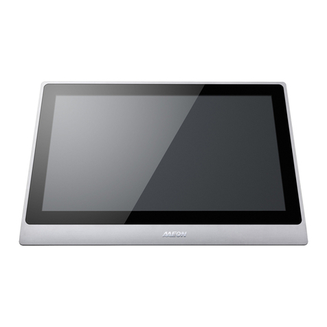
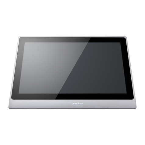
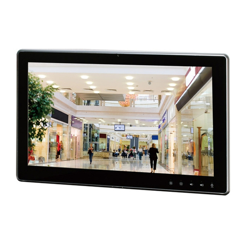
Multi-Touch Panel PC
ACP-5153
ACP-5153
15.6” Intel®AtomTM D2550
Processor
Fanless Multi-Touch Panel PC
ACP-5153 Manual 1st Ed
May 15, 2014

Multi-Touch Panel PC
ACP - 5153
i
Copyright Notice
This document is copyrighted, 2014. All rights are reserved. The
original manufacturer reserves the right to make improvements to
the products described in this manual at any time without notice.
No part of this manual may be reproduced, copied, translated, or
transmitted in any form or by any means without the prior written
permission of the original manufacturer. Information provided in
this manual is intended to be accurate and reliable. However, the
original manufacturer assumes no responsibility for its use, or for
any infringements upon the rights of third parties that may result
from its use.
The material in this document is for product information only and is
subject to change without notice. While reasonable efforts have
been made in the preparation of this document to assure its
accuracy, AAEON assumes no liabilities resulting from errors or
omissions in this document, or from the use of the information
contained herein.
AAEON reserves the right to make changes in the product design
without notice to its users.

Multi-Touch Panel PC
ACP - 5153
ii
Acknowledgments
All other products’name or trademarks are properties of their
respective owners.
AMI is a trademark of American Megatrends Inc.
Intel®, and Atom™are trademarks of Intel®Corporation.
Microsoft Windows®is a registered trademark of Microsoft
Corp.
IBM, PC/AT, PS/2, and VGA are trademarks of International
Business Machines Corporation.
All other product names or trademarks are properties of their
respective owners.

Multi-Touch Panel PC
ACP - 5153
iii
Packing List
Before you begin operating your PC, please make sure that the
following materials are enclosed:
ACP-5153 Multi Touch Panel PC
HDD screws
100/240V AC Adapter
Adapter Connector
DVD-ROM for manual (in PDF format) and drivers
If any of these items should be missing or damaged, please contact
your distributor or sales representative immediately.

Multi-Touch Panel PC
ACP - 5153
iv
Safety & Warranty
1. Read these safety instructions carefully.
2. Keep this user's manual for later reference.
3. Disconnect this equipment from any AC outlet before cleaning. Do
not use liquid or spray detergents for cleaning. Use a damp cloth.
4. For pluggable equipment, the power outlet must be installed near
the equipment and must be easily accessible.
5. Keep this equipment away from humidity.
6. Put this equipment on a firm surface during installation. Dropping
it or letting it fall could cause damage.
7. The openings on the enclosure are for air convection. Protect the
equipment from overheating. DO NOT COVER THE OPENINGS.
8. Make sure the voltage of the power source is correct before
connecting the equipment to the power outlet.
9. Position the power cord so that people cannot step on it. Do not
place anything over the power cord.
10. All cautions and warnings on the equipment should be noted.
11. If the equipment is not used for a long time, disconnect it from the
power source to avoid damage by transient over-voltage.
12. Never pour any liquid into an opening. This could cause fire or
electrical shock.
13. Never open the equipment. For safety reasons, only qualified
service personnel should open the equipment.
14. If any of the following situations arises, get the equipment
checked by service personnel:
a. The power cord or plug is damaged.
b. Liquid has penetrated into the equipment.
c. The equipment has been exposed to moisture.

Multi-Touch Panel PC
ACP - 5153
v
d. The equipment does not work well, or you cannot get it
to work according to the user’s manual.
e. The equipment has been dropped and damaged.
f. The equipment has obvious signs of breakage.
15. DO NOT LEAVE THIS EQUIPMENT IN AN ENVIRONMENT
WHERE THE STORAGE TEMPERATURE IS BELOW -20°C
(-4°F) OR ABOVE 60°C (140°F). IT MAY DAMAGE THE
EQUIPMENT.
FCC
This device complies with Part 15 FCC Rules.
Operation is subject to the following two
conditions: (1) this device may not cause
harmful interference, and (2) this device must
accept any interference received including
interference that may cause undesired
operation.
Caution:
There is a danger of explosion if the battery is incorrectly replaced.
Replace only with the same or equivalent type recommended by the
manufacturer. Dispose of used batteries according to the
manufacturer’s instructions and your local government’s recycling or
disposal directives.
Attention:
Il y a un risque d’explosion si la batterie est remplacée de façon incorrecte.
Ne la remplacer qu’avec le même modèle ou équivalent recommandé par le
constructeur. Recycler les batteries usées en accord avec les instructions du
fabricant et les directives gouvernementales de recyclage.

Multi-Touch Panel PC
ACP - 5153
vi
Below Table for China RoHS Requirements
产品中有毒有害物质或元素名称及含量
AAEON Panel PC/ Workstation
部件名称
有毒有害物质或元素
铅
(Pb)
汞
(Hg)
镉
(Cd)
六价铬
(Cr(VI))
多溴联苯
(PBB)
多溴二苯醚
(PBDE)
印刷电路板
及其电子组件
×
○
○
○
○
○
外部信号
连接器及线材
×
○
○
○
○
○
外壳
×
○
○
○
○
○
中央处理器
与内存
×
○
○
○
○
○
硬盘
×
○
○
○
○
○
液晶模块
×
○
○
○
○
○
光驱
×
○
○
○
○
○
触控模块
×
○
○
○
○
○
电源
×
○
○
○
○
○
O:表示该有毒有害物质在该部件所有均质材料中的含量均在
SJ/T 11363-2006 标准规定的限量要求以下。
X:表示该有毒有害物质至少在该部件的某一均质材料中的含量超出
SJ/T 11363-2006 标准规定的限量要求。
备注:
一、此产品所标示之环保使用期限,系指在一般正常使用状况下。
二、上述部件物质中央处理器、内存、硬盘、光驱、触控模块为选购品。

Multi-Touch Panel PC
ACP - 5153
vii
Contents
Chapter 1 General Information
1.1 Introduction................................................................ 1-2
1.2 Features .................................................................... 1-3
1.3 Specification..............................................................1-4
1.4 Dimension ................................................................. 1-7
Chapter 2 Hardware Installation
2.1 Safety Precautions....................................................2-2
2.2 A Quick Tour of the ACP-5153..................................2-3
2.3 Location of Connectors and Jumpers of Main Board
......................................................................................... 2-5
2.4 List of Jumpers..........................................................2-7
2.5 List of Connectors .....................................................2-8
2.6 Setting Jumpers ........................................................ 2-10
2.7 Auto Power Button Selection (JP1)........................... 2-11
2.8 Clear CMOS (JP2) ....................................................2-11
2.9 COM2 RI/+5V/+12V Selection (JP3)......................... 2-11
2.10 Touch Screen 4/5/8-wire Mode Selection (JP4) .....2-11
2.11 Brightness Control for 2nd LVDS (JP5) .................. 2-11
2.12 2nd LVDS Backlight Bias/PWM Mode Selection (JP6)
......................................................................................... 2-12
2.13 2nd LVDS Operating Voltage Selection (JP7) ........ 2-12
2.14 2nd LVDS Inverter Voltage Selection (JP8)............2-12
2.15 1st LVDS Inverter Voltage Selection (JP9)............. 2-12

Multi-Touch Panel PC
ACP - 5153
viii
2.16 1st LVDS Backlight Bias/PWM Mode Selection (JP10)
......................................................................................... 2-12
2.17 1st LVDS Operating Voltage Selection (JP11) ....... 2-13
2.18 Front Panel (CN1) ...................................................2-13
2.19 External +5VSB Input (CN2)...................................2-13
2.20 CPU Fan Connector (CN3) ..................................... 2-13
2.21 +5VSB Output w/SMBUS (CN4).............................2-14
2.22 SATA Port (CN5)..................................................... 2-14
2.23 External 12V Input (CN6)........................................ 2-14
2.24 Digital I/O Connector (CN7) ....................................2-15
2.25 Parallel Port Connector (CN8) (Optional)................ 2-15
2.26 +5V Output for SATA HDD Usage (CN9) ............... 2-16
2.27 USB Port #6 (CN10)................................................2-16
2.28 COM Port #6 (CN11)...............................................2-16
2.29 USB Port #5 (CN12)................................................2-17
2.30 COM Port #5 (CN13)...............................................2-17
2.31 USB Port #4 (CN14)................................................2-17
2.32 USB Port #3 (CN15)................................................2-18
2.33 COM Port #4 (CN16)...............................................2-18
2.34 LPC Expansion I/F (CN17)...................................... 2-18
2.35 COM Port #3 (CN18)...............................................2-19
2.36 COM Port #2 (CN19)...............................................2-19
2.37 Touch Screen (CN20) ............................................. 2-20
2.38 Stereo-R Channel (CN21)....................................... 2-20
2.39 2nd LVDS Output Dual Channel 18/24-bit (CN22) . 2-20

Multi-Touch Panel PC
ACP - 5153
ix
2.40 PS/2 Keyboard and Mouse Connector (CN23).......2-21
2.41 2nd LVDS Inverter (CN24)...................................... 2-21
2.42 Stereo-L Channel (CN25) ....................................... 2-22
2.43 1st LVDS Inverter (CN26) ....................................... 2-22
2.44 1st LVDS Output-Single Channel 18/24-bit (CN27) 2-22
2.45 2nd RJ-45 Ethernet Connector (CN28)................... 2-23
2.46 1st RJ-45 Ethernet Connector (CN29).................... 2-23
2.47 USB Port #1 and #2 (CN30).................................... 2-23
2.48 Audio Line In/Out and MIC (CN31).........................2-24
2.49 DVI/CRT Display Connector (CN32) Configured by
manufacturing..................................................................2-24
2.50 COM Port #1 (CN33)...............................................2-25
2.51 SIM Card Socket (CN34) ........................................ 2-26
2.52 CFast™ Disk (CFD1) ..............................................2-26
2.53 Mini Card/ mSATA (PCIE1).....................................2-27
2.54 DDR3 SODIMM Slot (DIMM 1) ...............................2-28
2.55 Hard Disk Drive Installation..................................... 2-29
Chapter 3 AMI BIOS Setup
3.1 System Test and Initialization ................................... 3-2
3.2 AMI BIOS Setup........................................................ 3-3
Chapter 4 Driver Installation
4.1 Introduction................................................................4-3
Appendix A Programming the Watchdog Timer
A.1 Programming .........................................................A-2

Multi-Touch Panel PC
ACP - 5153
x
A.2 ITE8783 Watchdog Timer Initial Program..............A-6
Appendix B I/O Information
B.1 I/O Address Map....................................................B-2
B.2 Memory Address Map............................................B-4
B.3 IRQ Mapping Chart................................................B-5
B.4 DMA Channel Assignments...................................B-5
Appendix C AHCI Setting
C.1 Setting AHCI......................................................... C-2

Multi-Touch Panel PC
ACP-5153
Chapter 1 General Information 1- 1
General
Information
Chapter
1

Multi-Touch Panel PC
ACP-5153
Chapter 1 General Information 1- 2
1.1 Introduction
The ACP-5153 Multi-Touch Panel PC supports Intel®Atom™
D2550 1.86 GHz processor. It is a PC-based system with 15.6"
color TFT LCD display, onboard Ethernet controller, multi-I/O port
interfaces and an audio controller. The ACP-5153 is a perfect
solution for comprehensive lifestyle computing applications.
For system integrators, this simple, complete, compact and highly
integrated system let you easily build an operator panel into your
applications. Common industrial applications include factory
automation systems, precision machinery, and production process
control. It is also suitable for many non-industrial applications,
including vending machine, and car park automation. Our operator
panel is a reliable, cost-effective solution to your application's
processing requirements.

Multi-Touch Panel PC
ACP-5153
Chapter 1 General Information 1-3
1.2 Features
15.6” SXGA TFT LED LCD
Onboard Intel®Atom™D2550 1.86GHz
Wide Screen with Projected Capacitive Multi-Touch
Anti-Scratch Surface: 7H Surface
IP65 Compliance Front Bezel & IPx1 Back Chassis
Fanless System
VESA 75/100

Multi-Touch Panel PC
ACP-5153
Chapter 1 General Information 1- 4
1.3 Specification
System
CPU
Onboard Intel®Atom™D2550 1.86 GHz
Processor
System Memory
DDR3 SODIMM x 1, Max. 4 GB (Default
is 2 GB)
Ethernet
10/100/1000Base-TX, RJ-45 x 2
LCD / CRT Controller
Intel®NM10
I/O Port
USB2.0 x 6 (2 on side; 4 on bottom)
RS-232 x 1
LAN x 2
DVI x 1
Line-out x 1
Power switch x 1
Storage Disk Drive
2.5”SATA Hard Disk Drive x 1/ CFast™
(Internal)
Expansion Slot
Mini-PCIe Card x 1
OS Support
Windows®XP 32-bit, Windows®7
32-bit, Linux Fedora
Mechanical
Construction
IP65 / NEMA 4 for plastic front bezel,
IPx1 for plastic chassie
Mounting
VESA 75/100

Multi-Touch Panel PC
ACP-5153
Chapter 1 General Information 1-5
Dimension
15.5”(W) x 10.7”(H) x 2.44”(D) (394mm x
372mm x 62mm)
Carton Dimension
20.47”(W) x 18.5”(H) x 9.06”(D) (520mm
x 470mm x 230mm)
Gross Weight
13.2 lb (6 kg)
Environmental
Operating Temperature
32oF~104oF (0oC~40oC) (w/o airflow)
Storage Temperature
-4oF~158oF (-20oC~70oC)
Operating Humidity
10% to 90%@ 40oC, non-condensing
Vibration
1 g rms/ 5-500Hz/ Operation (HDD)
Shock
20 G peak acceleration (11 msec.
duration)
EMC
CE/FCC Class A
Power Supply
AC Input
100/240V AC Power Adapter
LCD
Display Type
15.6”TFT LCD, LED
Max. Resolution
1366x768
Max. Colors
16.7M colors (6/8-bit for R, G, B)
Luminance (cd/m2)
300 nits
Viewing Angle
170o(H), 160o(V)
Backlight
LED

Multi-Touch Panel PC
ACP-5153
Chapter 1 General Information 1- 6
Backlight MTBF (Hours)
50,000
Touch Screen
Type
Projected Capacitive Touch (two points)
Resolution
2048x2048
Light Transmission
90%
Lifetime
10 million activations

Multi-Touch Panel PC
ACP-5153
Chapter 1 General Information 1-7
1.4 Dimension

Multi-Touch Panel PC
ACP-5153
Chapter 2 Hardware Installation 2-1
Hardware
Installation
Chapter
2

Multi-Touch Panel PC
ACP-5153
Chapter 2 Hardware Installation 2-2
2.1 Safety Precautions
Always completely disconnect the power cord
from your board whenever you are working on
it. Do not make connections while the power is
on, because a sudden rush of power can
damage sensitive electronic components.
Always ground yourself to remove any static
charge before touching the board. Modern
electronic devices are very sensitive to static
electric charges. Use a grounding wrist strap at
all times. Place all electronic components on a
static-dissipative surface or in a static-shielded
bag when they are not in the chassis
Table of contents
Other Aaeon Touch Panel manuals

Aaeon
Aaeon AGD-317R User manual

Aaeon
Aaeon AOP-9150 User manual

Aaeon
Aaeon APC - 8152 User manual

Aaeon
Aaeon PFM-541I User manual

Aaeon
Aaeon AHP-1122 User manual

Aaeon
Aaeon ACP-1104 User manual

Aaeon
Aaeon AOP-9120 User manual

Aaeon
Aaeon FOX-122 User manual

Aaeon
Aaeon ACP-5210 User manual

Aaeon
Aaeon ACP-5215 User manual

Aaeon
Aaeon OMNI-5215-SKU User manual

Aaeon
Aaeon OMNI-5155L User manual

Aaeon
Aaeon AMB-2000HT-E Series User manual

Aaeon
Aaeon AGD-312D User manual

Aaeon
Aaeon APC-8122 Series User manual

Aaeon
Aaeon ACD-110D User manual

Aaeon
Aaeon FOX-151 User manual

Aaeon
Aaeon LCD PC User manual

Aaeon
Aaeon AHP-1083 User manual

Aaeon
Aaeon FOX-80 User manual