7
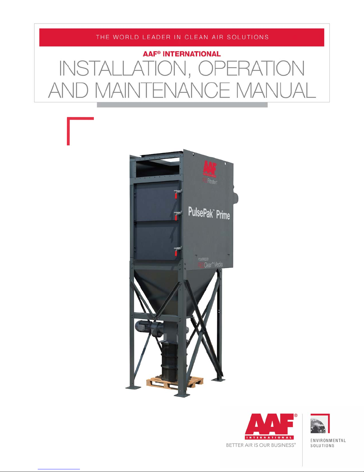
PulsePak PrimeGDED-IOM-216-B
hazard equipment, including, but not limited to, the necessity or effectiveness of
explosion hazard equipment or to the design, installation, operation, and
performance of such equipment. The basic standard for dealing with explosive dust
applications is from the National Fire Protection Agency (“NFPA”), NFPA 69:
Standard on Explosion Prevention Systems. This standard applies to the design,
installation, operation, maintenance, and testing of systems for the prevention of
explosions by means of various methods. The user shall be fully conversant with the
provisions of NFPA 69 and shall comply in full with all of its requirements.
By its very nature, AAF equipment is intended to be used to capture airborne
particulate matter, otherwise known as dust. There are various methods for dealing
with a dust explosion in a dust collector. These can include, but are not limited to,
the use of properly designed explosion vents, explosion suppressionsystems, or
flameless vents. The user shall understand which method is being used and who is
responsible for the design and supply of the equipment required.
When an explosive dust has been properly identified to AAF, the dust collector may
be structurally designed to withstand the internal pressure generated during the
explosive event and fitted with an explosion vent, or with multiple vents, designed
to safely discharge the pressure and the resulting fireball. The user shall review the
purchase order and the documents referenced within it to determine if explosion
protection equipment has been supplied by AAF International. Where this is the
case, review the appropriate sections of this manual that deal with the installation,
operation and maintenance of the equipment ordered.
When explosion protection systems are supplied by multiple vendors, it is the
responsibility of the user to coordinate between suppliers to ensure that the
equipment supplied by each vendor will work together to achieve the required
protection. For instance, if an explosion suppression system is being supplied by
parties other than AAF, it is incumbent on the user to ensure that the dust collection
equipment has been ordered to resist the internal pressure defined by the
suppression equipment supplier.
Dust collectors fitted with explosion vents must not be located indoors, unless
properly designed in accordance to NFPA regulations. The equipment shall be
oriented so that the vent will discharge to an unoccupied zone. Such a zone will be
prohibited to personnel and shall not include critical equipment or services such as
fuel storage tanks, flammable materials, fire hydrants, power distribution or
electrical control equipment, or similar. If the vent (or vents) are located on the
side(s) of the equipment the vent discharge area shall be isolated with barriers