AAF FAH-202-2P-MD Manual

SAAF Front Access Housings
with
SAAF
Cassette
Gas
Phase
Chemical
Filters
Installation, Operation and Maintenance Instructions
Better Air is Our Business ¤
1.0 Introduction
1.1 About this Document
This document contains the information necessary to properly receive,
assemble, install, operate, and maintain theAAF Front Access
Housing (FAH) filter bank and filters. The purchaser, installer, and
operator of the filter system MUST read and comply with this
document in its entirety prior to installation of the equipment and its
operation. Failure to comply with the requirements of this manual may
void the product warranty.
CAUTION
These instructions are specific to theAAF Front Access Housing
(FAH) filter bank and filters. All ancillary tasks including, but not
limited to, electrical and mechanical work, equipment handling, and
safety procedures must be performed in accordance with industry
accepted practice and all relevant local, state, and federal
government codes, laws, and policies.
Table of Contents
1.0 Introduction
1.1About this document
1.2 Packaging and shipping, receiving and inspection,
handling, and storage
1.3 Product descriptions
1.4 Product model designations
1.5 Product drawings
1.6Assembly — general comments
1.7 Related system equipment
2.0 Principles of Operation
3.0 Installation Instructions
3.1 Space requirements
3.2 Foundations and anchoring
3.3 Typical FrontAccess Housing (FAH) details
3.4 General filter bank erection procedure
3.5 Preparation for filter installation
3.6 Gas phase chemical filter installation
3.7 Prefilter installation
3.8 Pressure gauge
3.9After-filters
4.0 Start-up Instructions
5.0 Maintenance
5.1 Prefilter
5.2After-filter
5.3 Gas phase filter monitoring
5.4 Removal and replacement of particulate and gas phase
chemical filters
5.5 Disposal of used filters
5.6 Gaskets
5.7 General system maintenance
6.0 Troubleshooting
6.1 High pressure drop reading across the filter system
6.2 Visible discharge of particulate
6.3 Odors and smells
7.0 Spare Parts List
8.0 Equipment Characteristics, Operating Weights, and
Shipping Weights

1.2 Packaging and Shipping, Receiving and Inspection, Handling
and Storage
1.2.1 Packaging and Shipping: Unless otherwise defined in the
purchase order and agreed byAAF, the FAH and filters are
packaged for domestic transit and shipped FOB theAAF factory.
The method of shipment will be as specified in the customers
purchase order toAAF.
1.2.2 Receiving and Inspection: Obtain a copy of the purchase
order, the product drawing that was submitted by AAF in
association with the order, and a copy of the bill of lading, along
with any other shipping papers. Upon receipt of the equipment, or
any part thereof, these documents shall be used to ensure that the
correct product has been received.
For maximum protection, complete the following steps upon receipt
of the FAH filter bank and filters:
— Inspect the shipment and all associated documentation. Notify
the carrier immediately if there is any visible damage to the
packaging or the equipment, or a discrepancy in the shipping
papers and, if necessary, file an immediate claim with the carrier
against such damage or discrepancy.
— Confirm that the equipment received agrees with the contents
of the shipping papers.
— Confirm that the shipping documents agree with the purchase
order. Refer to the product drawing submitted for the order as
necessary.
— If it is determined that any equipment ordered on the purchase
order has not been delivered and is not accounted for in the
shipping papers contactAAF international immediately by calling
1-800-477-1214. Reference theAAF control number which will
be listed on the shipping papers.
Each shipment may include:
— Individually packaged FrontAccess Housings.
— Packaged particulate filters.
— Packaged gas phase chemical filter cassettes.
Note that the housings and the particulate and gas phase filters
may ship from different locations and be received at different times.
1.2.3 Handling and Storage: Following receipt, inspection, and
acceptance of the equipment, and prior to assembly and installation,
the FAH and the particulate and gas phase filters shall be handled
with great care. The components shall be retained and stored in their
protective packaging until immediately prior to installation. Care shall
be taken to ensure that the packages are not dropped or subjected to
any impact loads.
At all times the equipment shall be protected from exposure to weather.
The equipment shall be stored in a clean, dry, temperature controlled
environment.All items shall be stored on pallets so that they are
elevated above grade. The FrontAccess Housings and particulate and
gas phase filters shall not be stacked more than three (3) cartons high
to prevent crushing. Only FAH shall be stacked on FAH, particulate
filters on particulate filters, and gas phase filters on gas phase filters.
The gas phase filters ship inside a carton enclosed in transparent
protective plastic. Under no circumstances shall the filters be removed
from this plastic protection until immediately prior to installation.
Filter products shall not be stored in areas where they may become
contaminated by chemicals, either acids or alkalis, in liquid, vapor, or
gaseous form.
1.3 Product Descriptions
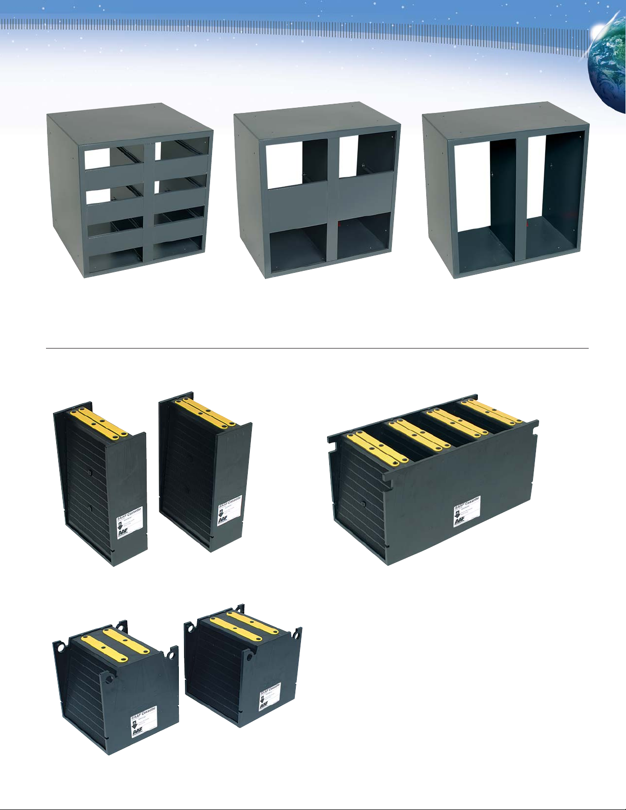
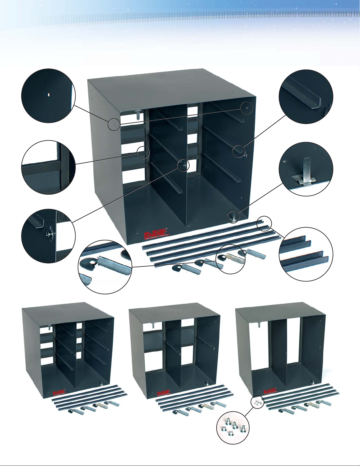
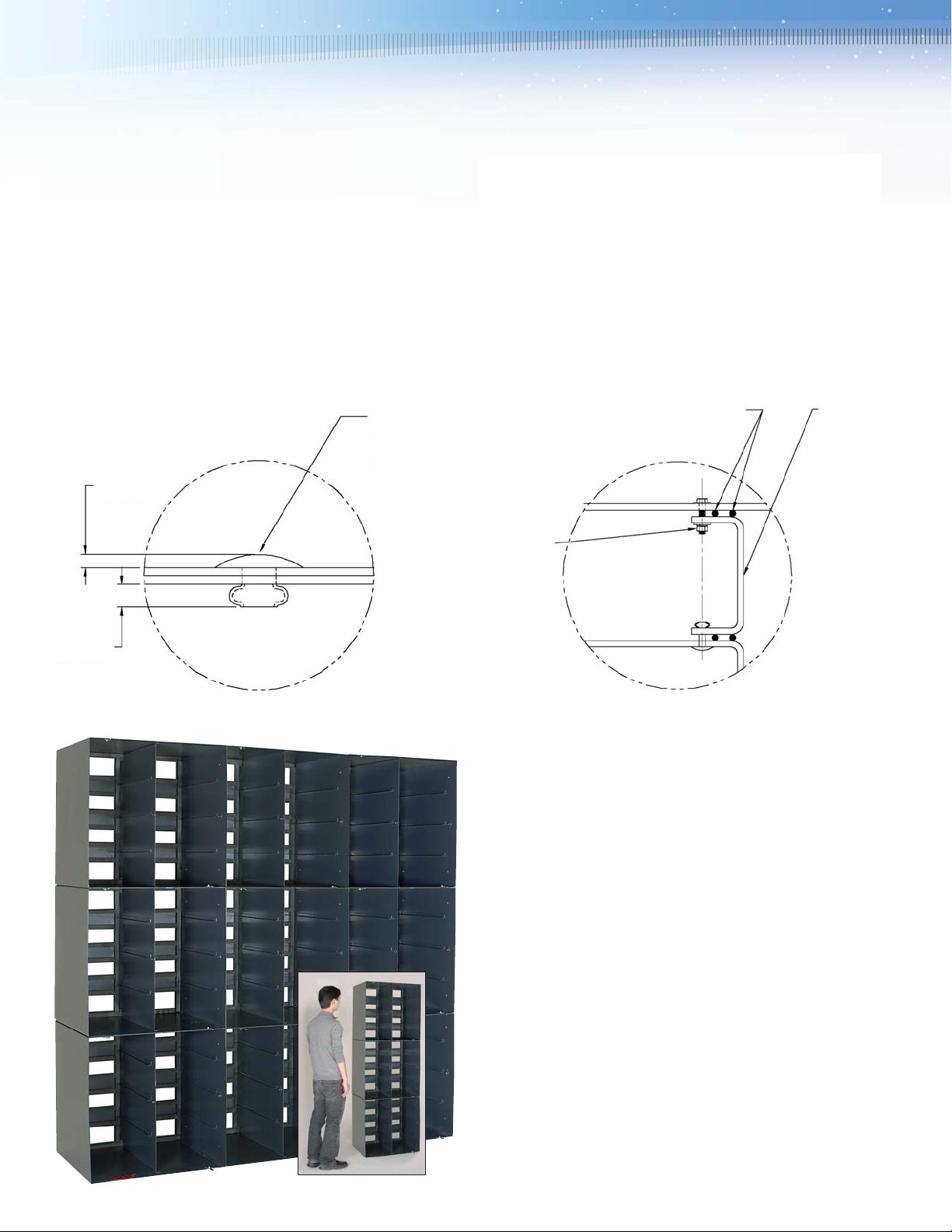
1.3.1 Front Access Housing (FAH): Each FAH will be received
individually in a carton. Depending on the quantity supplied, these
cartons may be palletized and banded together. The FAH is supplied
in three styles: Type MD, Type HD, or Type CG (as shown at top of
page 3) and will be the full size 2 high x 2wide housings shown, or
depending on the size of the filter bank required, may include half
size housings. Half size housings are available in half height (1 high
x 2wide) or half width (2high x 1 wide) sizes, except for the Type
CG which is only provided in the half width size. Half size housings
hold half the number of gas phase cassettes as full size housings
and use half size particulate filters.
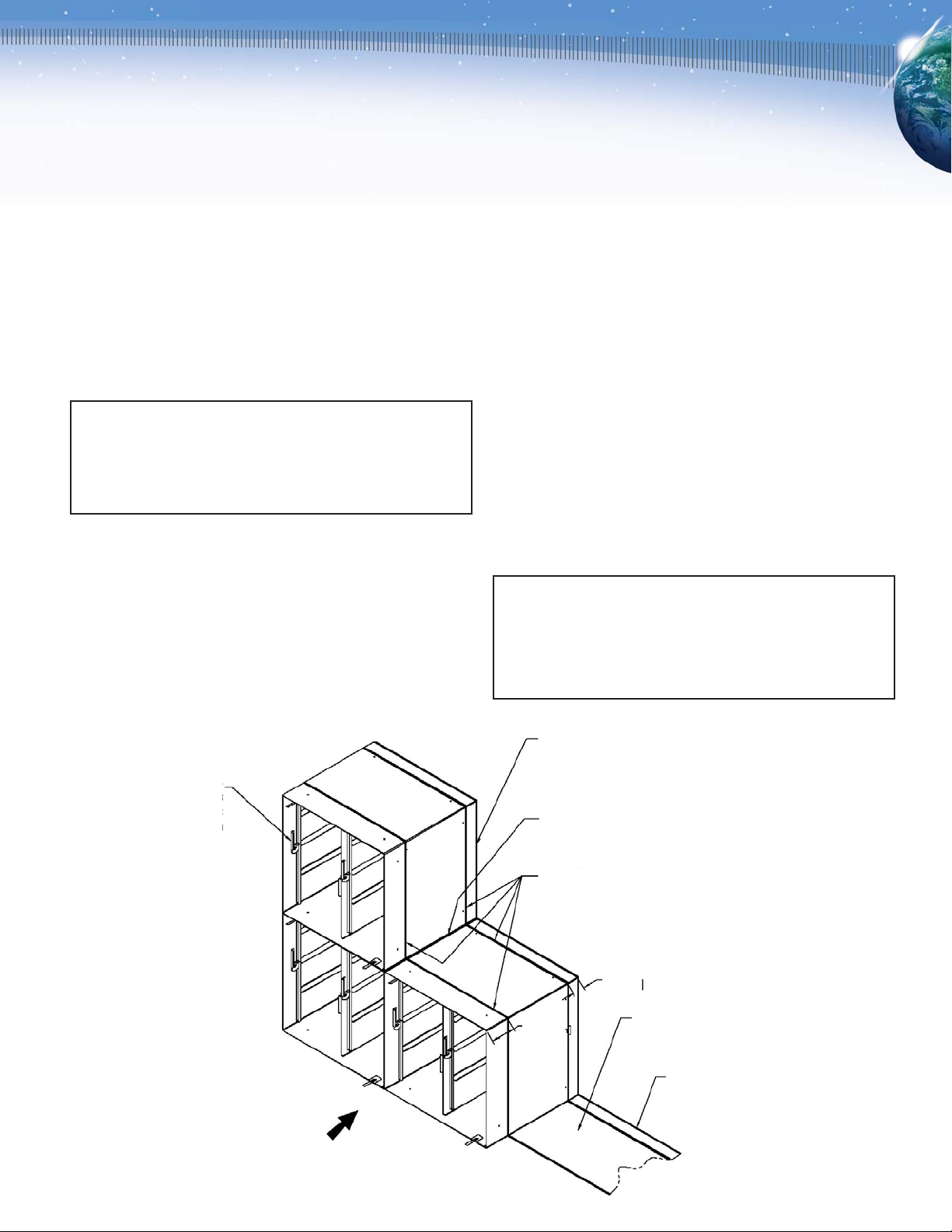
Any particular filter bank will be assembled using only one type of
housing (Type MD, Type HD or Type CG). Housing types will never
be mixed in a single filter bank.
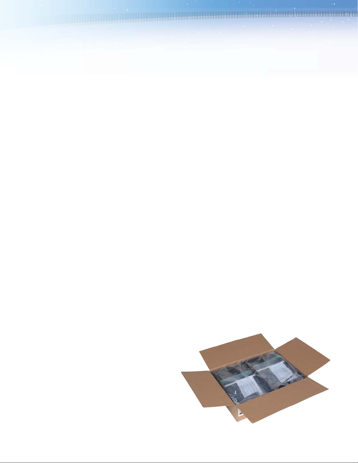
1.3.2 Gas Phase Chemical Filter Cassettes: Gas phase filter
cassettes are shipped in cartons and plastic bags. The carton
shown contains a single 6 high x 24 wide x 18 deep Type MD
cassette which is supplied as two (2) 6 high x 12 wide x 18 deep
half cassettes.
2

Model FAH-202-2P-MD housing holds
four (4) MD cassettes. Model FAH-202-2P-HD housing holds
two (2) HD cassettes. Model FAH-202-2P-CG housing holds
two (2) CG cassettes.
Leaving air face of the housings is shown.
6 high x 24 wide x 18 deep Type MD cassette ships in two halves.
12 high x 24 wide x 12 deep Type HD cassette ships in two halves.
24 high x 12 wide x 12 deep Type CG cassette ships in one piece.
The three (3) types of gas phase chemical filter cassettes that can be
supplied are as follows:
1.3.3 Particulate filters: Particulate filters will typically beAAF
PerfectPleat¤pleated filters. Depending on the size of the filter
frame ordered 24 high x 24 wide x 2 deep full size filters, 24
high x 12 wide x 2 deep, or 12 high x 24 wide x 2 deep half size
filters may be supplied. PerfectPleat 2 deep filters are packaged
12 to a carton.
3

1.4 Product Model Designations
The FAH model is designated as follows:
FAH - 202 — 2P —MD
Copies of the appropriate drawings will have been supplied as part of
theAAF submittals in response to the purchase order. Obtain and
review these drawings before proceeding with the assembly and
installation of the filter bank. The assembled filter bank drawings
include the following details for filter bank sizes 102 (1 high x 2wide)
through 812 (8 high x 12wide):
— Overall filter bank dimensions
— Shipping weights
— Operating weights
— Sizes and quantities of FrontAccess Housings required
— Sizes and quantities of filters required
— Details of the gas phase chemical media supplied
— Details of the particulate filters supplied
— Pressure losses across the filter bank at nominal airflow design
velocities
— Installation and assembly details
1.6 Assembly — General Comments
As indicated previously, the individual components that will comprise
the filter bank will ship separately and will be required to be
assembled and installed on site. Refer to Section 3.0, Installation
Instructions, of this manual for further detailed instructions. Consult
with an experienced installer to obtain an accurate estimate of the
time, personnel, and equipment resources and tools that will be
required to complete the assembly and installation of the filter bank.
Site assembly will be limited to moving and lifting individual
components with a maximum weight of approximately 55 pounds (25
kg), riveting or screwing components together, and caulking.
Completion of the following preparations and provision of the following
items will be the responsibility of the installer or others:
— Site preparation
— Stainless steel rivets, as required
— Caulk, as required
— Sheet metal, or other duct, as required
— Sheet metal perimeter blank-off panels, as required
These items will not be supplied byAAF unless noted specifically in
theAAF quotation and in the accepted customer purchase order.
Supports Type MD cassettes
Supports a 2 deep particulate pre-filter,
if required.
Is nominally 2 high x 2wide
FrontAccess Housing
FAH model numbers available are:
Type MD Type HD Type CG
FAH-202-2P-MD FAH-202-2P-HD FAH-202-2P-CG
FAH-102-2P-MD FAH-102-2P-HD FAH-201-2P-CG
FAH-201-2P-MD FAH-201-2P-HD
The assembled filter bank model number is typically designated as follows:
FAH - 608 - 2P - MD
In this case the - 608 - indicates a filter bank that is nominally
6 high x 8 wide.
1.5 Product Drawings
Details of individual FrontAccess Housings are shown on the
followingAAF drawings:
FAH AAF Drawing Number
FAH-202-2P-MD 114D-3026127
FAH-102-2P-MD 114D-3027273
FAH-201-2P-MD 114D-3027281
FAH-202-2P-HD 114D-3027869
FAH-102-2P-HD 114D-3027901
FAH-201-2P-HD 114D-3027877
FAH-202-2P-CG 114D-3027539
FAH-201-2P-CG 114D-3027513
Details of the assembled filter banks are shown on the following
AAF drawings:
FAH Filter Bank AAF Drawing Number
FAH-XXX-2P-MD 114D-3027919
FAH-XXX-2P-HD 114D-3028271
FAH-XXX-2P-CG 114D-3027919
4

NO WELDING WILL BE REQUIRED.
In general, assembly of the filter bank will consist of the following:
— Preparation of the installation location
—Transportation of all components to the installation location
— Unpacking the FrontAccess Housings
—Assembling and installing the FrontAccess Housings
—Sealing the filter bank perimeter to prevent by-pass of unfiltered air
— Unpacking gas phase chemical filter cassettes
— Installing gas phase chemical filter cassettes
— Unpacking particulate filters
— Installing particulate filters
— Cleaning the site
— Start-up and commission of the filter system
1.7 Related System Equipment
Ventilation systems will often include other equipment including but
not limited to:
—Fan(s)
—Dampers
—Weather louvers
—Air tempering equipment
— Other filter banks
— Instrumentation
— Electronic instrumentation and controls
—Ductwork
Neither the interface of these items with the filter system supplied by
AAF, nor the installation, operation and maintenance of these items is
covered in this manual.
Whether these items are supplied byAAF or by others, consult the
documentation specific to these products for appropriate instructions.
2.0 Principles of Operation
An understanding of the design and operating principle of the Front
Access Housings with Gas Phase Chemical Filters is useful for
effective installation, operation and maintenance. The system is
intended to remove gaseous contaminants from intake, re-circulated,
or discharged ventilation air. Examples of such contaminants may be
nuisance odors and smells that may cause domestic and
neighborhood discomfort and reduce workplace productivity, or harmful
gases that may cause damage to health, plant and product in industrial
applications. The heart of the system is theAAF SAAF Cassette. This
is a high impact plastic frame that supports various types of dry,
granular, chemical media between perforated screens that allow air to
move through the filter. The SAAF Cassette is designed to support the
chemical media in a V-bank configuration of media beds that maximizes
the media exposed to the air stream, reduces the air stream velocity
through the media bed, maximizes energy efficiency, and maximizes the
removal of contaminants and the life of the product. The method of
contaminant removal is through a combination of the physical property of
adsorption and the chemical process of oxidation.AAF offers a variety of
impregnated and un-impregnated dry granular media to handle a wide
range of contamination problems. For more information onAAFs gas
phase air cleaning products contact yourAAF representative.
TheAAF Front Access Housing (FAH) is one of the various framing
and support systems designed to support the SAAF Cassette in the
air stream and to allow easy installation, operation and maintenance
of the system.
3.0 Installation Instuctions
Consult the product drawing(s) submitted on this order before
proceeding.
3.1 Space Requirements: Aminimum of 24 clear space must be
available at the rear, or downstream side, of the filter bank and 36
clear space at the front, or upstream side, of the filter bank for access
to perform routine maintenance.Additional space may be required for
inlet and outlet ductwork.
3.2 Foundations and Anchoring: The foundation must be designed to
be adequate to support the filter bank operating weight, and any
seismic, live or other loads (if any), with a sufficient factor of safety as
determined to comply with the requirements of all applicable governing
codes, standards, and laws. Ensure that the foundation surface is level
and smooth before proceeding. The filter frame is designed for
operation in indoor locations without any unusual loading condition,
other than the static loading from the filters and the pressure loss
across the filter bank. For this reason, the lower housings are not
intended to be anchored to the foundation. If anchors are used the
installer shall ensure that the anchor heads do not interfere with the
installation of the lowest tier of gas phase filter cassettes. If the frame
bank is required to withstand unusual or dynamic loads, then special
anchoring arrangements featuring removable supports may be required.
5

FAH-202-2P-MD
Entering air face of the housings is shown. Locking handle support tab ships loose
with the Type CG housing.
FAH-202-2P-HD FAH-202-2P-CG
Cassette support angle
Pre-filter latch
in closed position
Cassette sealing and
locking channel
Filter sealing locking handle
Filter face sealing gasket
Locking handle support tab
Rivet hole, 4 each side and
top and bottom
The entering air face of an FAH-202-2P-MD housing is shown.
3.3 Typical FAH Details
6

Each individual FAH is specifically designed to accommodate and
securely sealAAFs gas phase chemical filter cassettes. Each housing
incorporates a unique, patent pending, filter sealing system to ensure that
the contaminated air passes through the filter and does not by-pass the
system. Each FAH is supplied complete with four (4) sealing and locking
channels as illustrated. The locking handle support tabs are shipped
installed on the FAH-(202)(201)(102)-2P-MD and FAH-(202)(201)-2P-HD
housings, but ship loose with the FAH-(202)(201)-2P-CG and the
FAH-102-2P-HD housings for installation after the gas phase filters have
been inserted into the housing (see illustration bottom page 6).
3.4 General Filter Bank Erection Procedure
CAUTION
The maximum number of FrontAccess Housings that may be
stacked vertically without intermediate supports is four high. There
is no limit to the width of a built-up filter bank.
After removing the FrontAccess Housings from the cartons, prepare
to arrange and stack the individual housings to form the filter bank
shown on theAAF submittal drawing and in Figure 1 below.
To ensure that the erected frame is properly sealed to prevent by-pass
of air around the filters, it is important to comply fully with the following:
3.4.1 Support Surface: The support surface under the base of the
frame shall be level, smooth, clean, and dry. The location shall be
protected from the weather and shall not be subject to wetting or flooding.
3.4.2 Caulking and Sealing: Caulk generously beneath, between,
and around the FrontAccess Housings as shown in Figures 1 and
3. Locate the lines of caulk as shown and as follows:
Two (2) unbroken transverse lines between horizontal and vertical
rows, across the entire width of the filter bank at each level
beginning at the support surface.
One orthogonal line of caulk across the full depth of the frame at
any point where the side panel of the FAH joins to the top or bottom
of the housing forming a corner that connects to a similar corner on
another housing. Such joints will occur at the connections between
the support base and the lowest tier of housings, any two perimeter
housings, or any four internal housings.
Caulk all seams on the face of the filter bank on the air leaving side.
Provision of the caulk will be the responsibility of the installer or
others. This item will not be supplied byAAF unless noted
specifically in theAAF quotation and in the accepted customer
purchase order. The caulk to be used shall be a long life, flexible,
non-drying caulking material. The caulk supplier shall ensure that
the caulk shall meet the customer specifications for the application
in which it is being used.
CAUTION
Many installations prohibit the use of certain caulking materials
such as Silicone. The use of materials containing VOCs should
also be avoided as they may have a negative effect on the life
of the gas phase filters.
Figure 1
TYPICAL CAULKING DETAIL TO PREVENT UNFILTERED AIR BY-PASS
AAFs Patent Pending
SAAF Seal High Integrity
Sealing System
Caulk Face Joint Fully (Caulk Supplied by Others)
Caulk Orthogonal Joint Fully (Caulk Supplied by Others)
Caulk Transverse Joint Between Frames as Shown to Prevent By-pass
(Caulk Supplied by Others)
2
[50mm]
4
[100mm] Bearing Surface Shall be Level and Smooth
Caulk Seal at Floor Level
(Caulk Supplied by Others)
Airflow
7

3.4.3 Connecting the Front Access Housings: The individual
housings shall be riveted together using the holes provided, as
shown in Figure 2. Four (4) rivet holes are provided on each side of
the housing and on the top and bottom. When connecting to
adjacent housings all rivet holes must be used.
Provision of the rivets will be the responsibility of the installer or
others. This item will not be supplied byAAF unless noted
specifically in theAAF quotation and in the accepted customer
purchase order.
It is recommended that stainless steel rivets be used. Check the
first frame installations to ensure that the installed rivets do not
interfere with the installation of the chemical filter cassettes.
Blind Rivets 532"
Dia. Stainless Steel
0.063" — 0.125"
Grip (Rivets
Supplied by Others)
Typical Rivet Detail
18" Maximum
18" Maximum
Figure 2
3.4.4 Sealing the Perimeter of the Filter Bank: The perimeter of
the filter bank shall be sealed to prevent the by-pass of air around the
filter bank. Suggestions for accomplishing this are shown in Figure 3.
Provision of the ductwork and/or sheet metal panels will be the
responsibility of the installer or others. This item will not be supplied
byAAF unless noted specifically in the AAF quotation and in the
accepted customer purchase order.
Pay particular attention to caulking around the perimeter to achieve
a complete seal. Detailed caulking instructions are provided in
paragraph 3.4.2.
Use Sheet
Metal Panels
to Seal Top
and Sides
of Frame
Bank as
Necessary
Suggested Ductwork Connection Detail
Figure 3 Caulk Seal Typ.
(caulk Supplied by Others)
Hardware Supplied
by Others
3.5 Preparation for Filter Installation: At this time a filter bank
similar to that shown (lower left) will have been erected.
In order to maximize the life of the gas phase chemical filters and the
particulate filters, it is recommended that filter installation be the final
installation task before start-up and commissioning of the system. In
preparation for filter installation, it is recommended that the following
be completed:
— Completely clean the system to remove all construction debris
and dirt, sweep and vacuum to remove visible dirt.
— Damp wipe all surfaces to remove dust.
— Finalize and complete all caulking.
— Finalize and complete all painting.
It is recommended that all cleaning materials and paints used in the
system be free of solvents. If this is unavoidable, it is recommended
that sufficient time be allowed for complete drying to occur and for the
VOCs to disperse before installing the filters. This process can be
accelerated by blowing down the system; i.e., operating the fan
without the filters to ventilate the system. It is recommended that a
blanket style construction filter be installed at the inlet to the system to
prevent construction dust from being drawn into the system. Consult
8

with yourAAF representative to obtain an appropriate product. Also,
before blowing down the system, check that it is safe to operate the
fan without the pressure load of the gas phase chemical filters.
Consult theAAF submittal drawing for pressure information.
3.6 Gas Phase Chemical Filter Installation: The following
instructions are specific to the installation of the MD gas phase
chemical filter cassettes into the appropriate FAH-XXX-2P-MD filter
frame. Unless specifically mentioned otherwise, the procedure for
installing the HD and CG cassettes will be exactly the same.
3.6.1 Check the Gaskets in the Face of the Front Access
Housings: Before proceeding with installation, inspect the gaskets
located in the face of the housings to ensure that they have not
been damaged or become loose during installation and cleaning.
Correct any problems.
3.6.2 Prefilter Locking Tabs:
Ensure that the pre-filter
locking tabs are in the open
position before proceeding.
See the detail at right.
3.6.3 Preparing the Cassette for Installation: Remove the cassette
from its carton and plastic bag. You may notice that
each cassette or half
cassette is
accompanied by
a plastic bag
containing loose
gaskets (see
right). These are
supplied for use
when the cassette
is being installed
into anAAF Side
Access Housing (SAH)
and are not required for
installation into
the FAH frame
bank. DISCARD
THESE
GASKETS.
3.6.4 Handling of the Cassette: TheAAF SAAF Cassette is
designed to be sturdy and to support a significant weight of chemical
media. However, it should not be handled roughly. The cassette
should always be lifted with two hands, one beneath each side
panel as shown in the following installation pictures. The cassette
should never be lifted, supported, or carried by a single side panel.
3.6.5 Installation of the Cassette in the FAH: Install the cassettes
as shown in the sequence below starting with the bottom cassette.
The bottom cassette rests on the lower panel of the FAH housing.
Subsequent cassettes are supported on tracks. Slide each half-cassette
into the FAH and push it firmly against the gasket that is located in
the face of the housing. Repeat this process until all of the tracks in
the FAH have been filled.
Step 1: Insert the filter into the FAH.
Step 2: Slide the filter into the FAH.
Step 3: Push to engage the gasket in the face of the FAH.
9

3.6.6 Preparing the FAH-202-2P-CG, FAH-201-2P-CG, and FAH-
102-2P-HD Housings for Sealing and Locking of the Cassettes:
The FAH-202-2P-CG and FAH-201-2P-CG housings support a single
cassette in each 2 high x 1wide cavity, while the FAH-102-2P-HD
housing supports a single half cassette in each 1’ high x 1’ wide
cavity. If installed prior to cassette installation, the locking handle
support tabs, which are center-mounted on the vertical panels, would
interfere with the installation of the cassette. For this reason they are
shipped loose with the FAH for installation after the cassette has been
installed. Locate the locking handle support tabs and insert them into
the left hand, right hand, and center panels of the FAH, as shown in
the illustration below.Adjacent housings will share a set of tabs.
Note that the locking handle support tabs are shipped installed
on MD and most HD housings.
3.6.7 Sealing and Locking the Cassettes in Place: The patent
pendingAAF SAAF Seal system ensures that the gas phase
chemical filter cassettes are properly sealed into position against
the face gasket to prevent the by-pass of contaminated air around
the filter. The system is designed to be completely effective and to
be simple to operate. Follow the sequence shown in the
accompanying illustrations and as described below:
Step 1: Take one cassette sealing and locking channel.
Step 3: Take one filter seal locking handle.
Step 2: Locate the channel against the left side of the center vertical cassette support panel,
inside the locking handle support tab, with the channel legs facing away from the cassette.
10

Step 4: Insert the filter seal locking handle into the locking channel so that the locking
handle support tab protrudes completely through the hole in the locking handle.
Step 8: Again, repeat the process on the left and right hand side panels of the FAH
housing until each row of half-cassettes is locked in position at both sides.As before,
the handle on the left hand side of the panel always rotates downwards and the handle
on the right hand side of the panel always rotates upwards.
Step 5: Making sure that the locking handle is hooked behind the front flange of the
locking handle support tab and cannot slip off, rotate the locking handle downwards so
that the face of the handle engages the web of the channel forcing it against the
cassettes and pushing them into the housing to compress the face gasket.
Step 7: Now, repeat the process on the right hand side of the center vertical cassette
support panel. The handle on the right hand side of the panel rotates upwards.
11
Step 6: Rotate the locking handle until it is completely seated with the handle in the
vertical position. The locking handle is self positioning and cannot be over-rotated.

Repeat the process of gas phase cassette installation and sealing
until all housings are filled with sealed cassettes as shown below.
3.7 Prefilter Installation: The prefilter is offered as an option with the
FAH. It is normally not necessary to include the prefilter if the system
includes a separate bank of inlet filters. Where a separate inlet filter
system is not provided, it is highly recommended that prefilters be
used to prevent the build up of lint and dust on the face of the gas
phase chemical filters.
Install the prefilters as shown in the sequence at right. Each individual
FAH can accommodate one prefilter.A standard 24 x 24ASHRAE
style filter will fit into the size 202 housing and a standard 24 x 12
ASHRAE style filter will fit into the size 201 and 102 housings. The
FrontAccess Housings are designed to accept a 2 deep pre-filter
only. For best resultsAAF recommends the use of the MERV 7 rated
PerfectPleat.
Place the prefilter into the open face of the FAH with the pleats
arranged vertically. However, it may be necessary when installing
some half size filters to arrange the pleats horizontally.
Step 1: Insert the prefilter into the FAH.
Step 2: Engage the two spring loaded prefilter holding tabs.
Step 3: The installed prefilter.
12

Repeat the process of prefilter installation until all housings are filled
with latched prefilters as shown below.
3.8 Pressure Gauge: It is recommended that a pressure gauge be
installed across the filter bank to indicate when the prefilter needs to
be replaced. The pressure gauge will register the pressure differential
across the bank.As the prefilter loads with dirt the resistance to the
airflow, and consequently, the pressure across the filter will increase.
The pressure across the gas phase chemical filter will remain
constant since this filter collects gas molecules and not particulate. If
a pressure gauge has not been included in the customers purchase
order, discuss the pressure gauge options with yourAAF representative.
If a pressure gauge has been included in the order, refer to the
specific installation instructions supplied with the gauge.
3.9 After-filters: Some gas phase chemical filter media may
discharge a small plume of dust on fan start-up when the filter system
is first operated. This may result in dust being deposited on the
downstream side of the filter bank. There are generally two ways to
deal with this:
— In industrial applications that are not particularly sensitive to small
amounts of dust, this initial plume is allowed to blow off and the
deposited dust is swept up or vacuumed.
— In applications that are sensitive to dust, it is recommended that
an after-filter similar to the prefilter discussed above be supplied on
the downstream side of the filter bank. This will require an
additional frame bank to be mounted in the duct on the downstream
side of the gas phase chemical filters. In addition to the MERV 7
after-filter a higher rated air filter may also be installed to provide a
significantly improved level of air cleanliness in the space to be
ventilated. Many options are available up to HEPAand ULPA filter
systems. If an after-filter or higher efficiency final filter with
appropriate support frames have not been included in the
customers purchase order, discuss the additional filter options with
yourAAF representative. If any of these items have been included
in the order, refer to the specific installation instructions supplied
with those items.
4.0 Start-up Instructions
When the fan system is started up, ensure that the airflow volume is
controlled so that the actual airflow velocity across the filter bank does
not exceed the rated face velocity shown on theAAF submittal
drawing. If there is any doubt about the required face velocity the
default maximum velocities shall be as follows:
— MD and CG cassettes: 500 feet per minute
— HD cassettes: 250 feet per minute
Immediately on start-up examine the filter system for any apparent air
leaks or other anomalies.Air leaks may be detected by noise or by
use of a synthetic smoke puffing device at the internal and perimeter
joints and seams of the filter bank installation. Correct or repair any
discrepancies, as necessary. Repeat this examination after 24 hours
of operation and again after one week of operation.
Monitor the pressure drop across the filter bank to ensure that the
filters are operating within the pressure range expected and to ensure
that the pressure drop is not too high. Consult theAAF drawing for the
expected clean filter pressure differentials.
5.0 Maintenance
5.1 Prefilter: If a prefilter has been included as part of the system,
record the pressure drop weekly to obtain the status of the particulate
filter. Anormal particulate prefilter can be expected to last for between
2 and 3 months before reaching its final recommended pressure drop
(see theAAF drawings for details). However, under heavier or lighter
dust loading conditions this may vary.At an airflow velocity of 500 feet
per minute the 2 deepAAF PerfectPleat filter can be expected to
have an initial pressure drop in the range of 0.35 water gauge. The
recommended final pressure drop is 1.0 water gauge. This means
that when a pressure drop increase of 0.65 water gauge has been
recorded it is time to change the prefilter.
13

5.2 After-filter: If an after-filter has been installed in the system to
collect an initial plume of dust that might be blown from the gas phase
chemical filters, it can eventually be removed from the system to reduce
the energy required to operate the system. Monitor the pressure drop
across this filter, and when the pressure ceases to increase it is safe to
remove this filter from the system. This should typically be no longer
than after 40 hours of operation. If after-filters still have significant life
remaining at the time of removal (based on the pressure drop reading)
they should be retained for re-use as after-filters following the change-out
of the chemical filters or be used as replacements for the prefilters.
5.3 Gas Phase Filter Monitoring: Adiscussion of sophisticated gas
phase filter monitoring is beyond the scope of this manual.At its most
simple, when the filter is used to remove nuisance odors, the time to
change out the gas phase chemical media cassette is when the odor
begins to be regularly detected on the clean side of the filter bank. In
more stringent applications where the system is supplied to protect
health and / or high value plant and product, active real time
electronic and passive coupon corrosion monitoring systems are
available to determine the performance of the system. The remaining
life of the media in the SAAF Cassette can be determined by taking a
sample of media and returning it toAAF for analysis. Consult with
yourAAF representative regarding active and passive monitoring
systems and media sampling for remaining life analysis.
5.4 Removal and Replacement of Particulate and Gas Phase
Chemical Filters: Removal of filters will be the reverse of the
installation process described earlier in this manual. Filter replacement
will be carried out exactly the same as at initial installation.
5.5 Disposal of Used Filters: Used chemical filters and particulate
filters shall be packaged and disposed of in full accordance with all
required and applicable laws and regulations. Consult with local
environmental control authorities such as local, state, and federal EPA
& OSHAauthorities for direction. Material Safety Data Sheets (MSDS)
are available on all products supplied byAAF. Contact your AAF
representative for further information.
5.6 Gaskets: The proper maintenance of the face gaskets on the
leaving air face of each FAH is critical to the performance of the
system. Check the gaskets carefully whenever the gas phase
chemical filters are replaced. If gaskets are worn, frayed, or
compressed to the point where they do not recover when the filter
seal is released they should be replaced. Check the seal between the
gas phase chemical filter cassette and the FAH on the air leaving face
of the housings whenever new SAAF Cassettes are installed.
5.7 General System Maintenance: Ducts, filter support frames,
access doors, and other system infrastructure should be checked at
least every 6 months. Examine all components for the following:
5.7.1 Cleanliness: Sweep and vacuum all standing dust or dirt in the
system and damp wipe all surfaces. Be mindful of the impact of
cleaning solvents on the performance and life of the gas phase
chemical filters and take appropriate precautions to protect the system.
5.7.2 Water: The system should be completely dry at all times. The
presence of standing water, condensation, or dampness is
detrimental to the performance and life of the system. Determine
and remove the cause for the presence of water in the system, dry
the system, and examine all components for the presence of mold
and other biological growth. Remove all contamination, clean and
sterilize as necessary.
5.7.3 Filter Bank Integrity: Ensure that all filter housings contain
the appropriate filter elements, both particulate and gas phase, and
that these elements are correctly installed. Check for missing or
improperly installed latches and review the filter seals. Check for air
leaks between the housings and seal with caulk as necessary.
5.7.4 Duct and System Integrity: Examine the entire system to
ensure that contaminated air cannot leak around the filter bank.
Check all perimeter seals and repair as necessary.
5.7.5 Corrosion: If metal components are corroded, repair the
corrosion and provide protective coatings as necessary. Be mindful
of the impact of painting on the performance and life of the gas
phase chemical filters and take appropriate precautions to protect
the system. Determine the source of the corrosion and rectify.
6.0 Troubleshooting
6.1 High Pressure Drop Reading Across the Filter System:
6.1.1 High Dust Loading: The most probable cause of high
pressure drop will be high dust loading of the particulate filters. The
rate of dust loading may not always be constant and may be
significantly affected by season and location; e.g., the timing of pollen
blooms, production schedules, and rural versus urban locations.
6.1.2 High Airflow Volume: High airflow volume may result from
improper fan sizing or improper control of the fan. When clean
particulate filters are installed in the system the pressure drop
across the system will decrease and the airflow will normally
increase. The airflow should be controlled through the use of
modulating dampers which are designed to keep the system
pressure constant or with the use of variable speed drives. If
desired, the filter system may also be slightly oversized so that it
will handle the higher airflow at the lowest system pressure without
exceeding the recommended filter face velocity.
14

6.1.3 Condensation: Humid air combined with cold surfaces may
result in condensation of moisture and blinding of both the
particulate and gas phase filters. This moisture can also result in
mold growth and corrosion which may also impact the performance
of the filter system. If condensation is a recurring problem,
dehumidification or other tempering of the air may be required.
System insulation may also be necessary. If the source of the
moisture is at the intake, weather hoods or weather louvers to
remove sensible moisture in the form of rain should be considered.
If the source of moisture is from leaking ducts repair the leaks.
6.1.4 Freezing: On air intake systems the presence of moisture in
the filters when caused by or combined with condensation, rain, snow,
sleet, or ice, and when subjected to freezing temperatures, can cause
the filters to freeze and become impassible. In such cases provide
intake protection systems to remove the cause of the problem.
6.2 Visible Discharge of Particulate:
6.2.1 Check for missing or damaged filters and system leaks.
Replace filters and re-seal as necessary.
6.2.2 Provide higher efficiency filters on the downstream side (air
leaving side) of the system.
6.3 Odors and Smells:
6.3.1 Check the performance of the gas phase chemical filters. If
the filters are no longer effective replace them.
6.3.2 Check for missing or damaged filters and system leaks.
Replace filters and re-seal as necessary.
7.0 Spare Parts List
It is recommended that the following spare parts be stored at the installation site for routine maintenance purposes. The quantities required will
depend on the size of the system. Consult with yourAAF representative to determine actual quantities required. Minimum recommended
quantities are provided in the table below.
AAF Part Number Description Recommended Spares
Refer to the original customer purchase SAAF cassette gas phase chemical filters One full replacement set of each type
order and theAAF submittal drawing. included in the system.
Refer to the original customer purchase Particulate filters One full replacement set of each type
order and theAAF submittal drawing included in the system.
114-3026184-1 (A) Cassette sealing and locking channel 10% of total quantity or a minimum of 5
114-3026192 (B) Filter seal locking handle 10% of total quantity or a minimum of 5
5241070 Locking handle support tab 10% of total quantity or a minimum of 5
5241062 Locking handle support tab 10% of total quantity or a minimum of 5
2500866 (A) Face gasket One full replacement set or a roll of 50 feet
114-3026184-2 (A) Cassette sealing and locking channel for 10% of total quantity or a minimum of 3
1’ high half size housings only
To order replacement parts call: 1-800-477-1214.
8.0 Equipment Characteristics, Dimensions,
Operating Weights, and Shipping Weights
See theAAF submittal drawing supplied on the specific order.
15

Better Air is Our Business ¤
AAF has a policy of continuous product research
and improvement and reserves the right to change
design and specifications without notice.
10300 Ormsby Park Place Suite 600
Louisville, Kentucky 40223-6169
www.aafintl.com
Customer Service 800.477.1214
Fax 800.254.3019
ISO Certified 9001-2000
'2006AAF International
GPF-3-115 NOV 06 QG 2M
SAAF Front Access Housings
with
SAAF
Cassette
Gas
Phase
Chemical
Filters
Installation, Operation and Maintenance Instructions
This manual suits for next models
7
Table of contents
Other AAF Water Filtration System manuals
Popular Water Filtration System manuals by other brands

Hydac
Hydac OLF-5 Installation and maintenance instructions

Everpure
Everpure EV9347-20 Installation and operation guide

Pentair
Pentair EVERPURE ENDURANCE SC Installation, operation, maintenance guide

PureEffect
PureEffect ULTRA-UC-DISINFECT manual

Carlisle
Carlisle DEVILBISS HAF-505 Service manual

UV Dynamics
UV Dynamics UVD320E Installation and maintenance manual