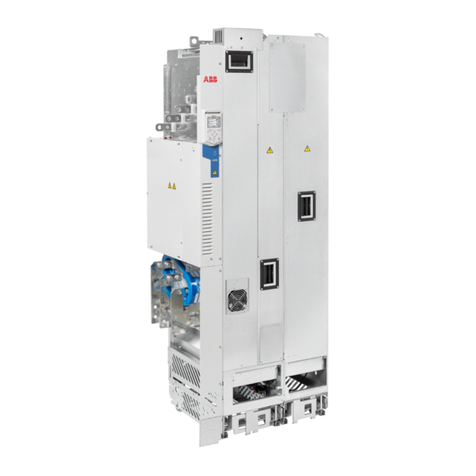
ABB ACH580-34 Installation manual

—
ABB DRIVES FOR HVAC
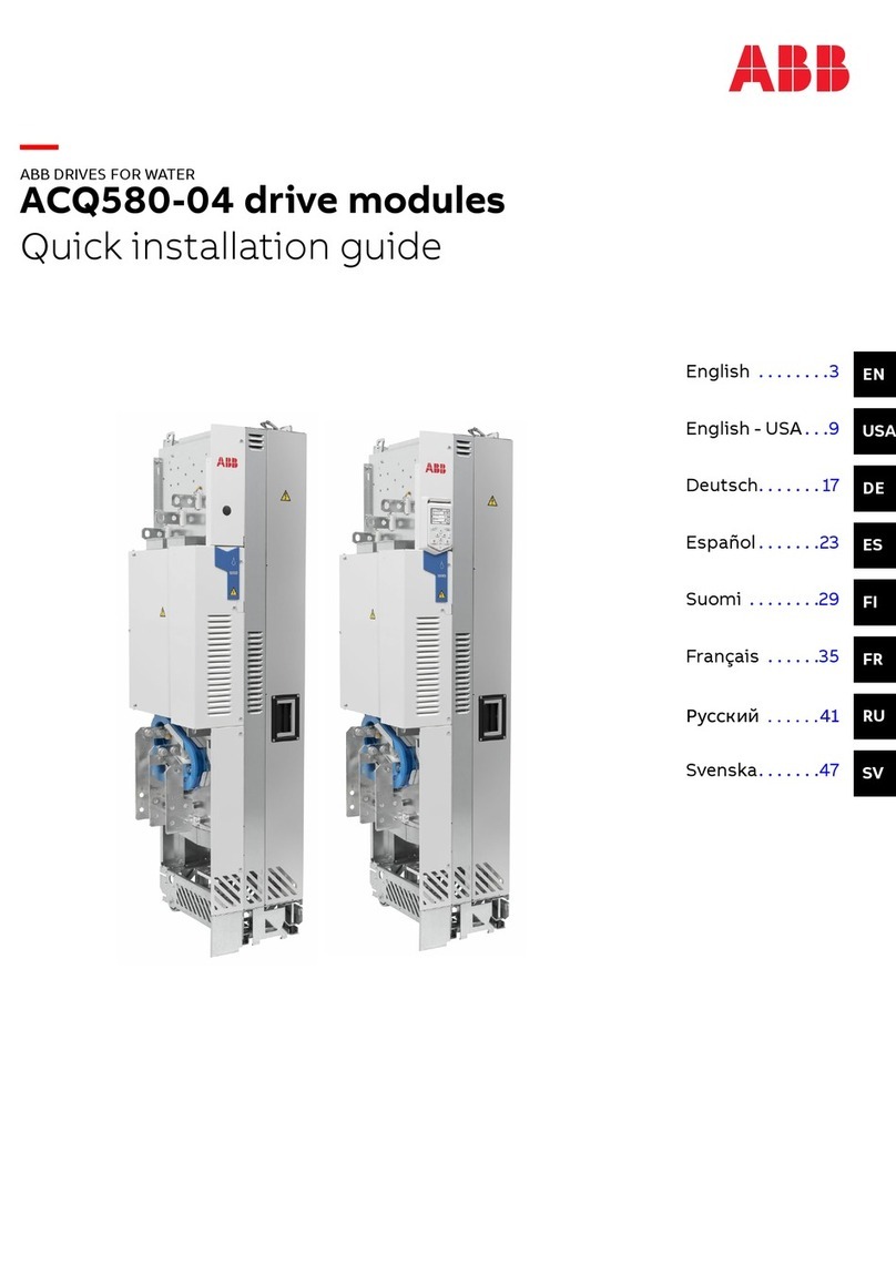
ACH580-34 drive modules
Quick installation and start-up guide
ENEnglish . . . . . . . 3
DADansk . . . . . . . 23
DEDeutsch . . . . . 45
ESEspañol . . . . . . 67
FISuomi . . . . . . . 89
FRFrançais . . . . . 111
ITItaliano . . . . . 133
NLNederlands . . 155
PLPolski . . . . . . . 177
PTPortuguês . . . 199
SVSvenska . . . . . 221
TRTürkçe . . . . . . 243
ZH
中文 ....... 265
3AXD50000424627 Rev E MUL
EFFECTIVE: 2022-09-21


EN – Quick installation and start-up
guide
This guide tells you briefly how to install the drive module into a 800 mm wide Rittal
VX25 enclosure and start-up the drive.
Obey the safety instructions
■General safety
These instructions are for all personnel who do work on the drive.
Obey the safety instructions of the drive. If you ignore them, injury or
death, or damage to the equipment can occur.
• Keep the drive in its package until you install it. After unpacking, protect the drive
from dust, debris and moisture.
• Use the required personal protective equipment: safety shoes with metal toe cap,
safety glasses, protective gloves and long sleeves, etc. Some parts have sharp
edges.
• When the drive or connected equipment is energized, do not do work on the drive,
motor cable, motor, control cables or control circuits.
• Do not do work on the drive when a rotating permanent magnet motor is
connected to it. A rotating permanent magnet motor energizes the drive, including
its input and output power terminals.
•Do not use the module extraction/installation ramp with plinth heights that exceed
the maximum allowed height.
• Attach the module extraction/installation ramp carefully.
• Make sure that the module does not fall over when you move it on the floor: To
open the support legs, press each leg a little down and turn it aside (1, 2). Whenever
possible attach the module also with chains. Do not tilt the drive module. It is
heavy and its center of gravity is high. The module overturns when tilted more
than 5 degrees. Do not leave the module unattended on a sloping floor.
Do not roll the module on its wheels for a longer distance than what is required
for inserting or extracting the module. To move the module to or from the vicinity
of the cabinet, lay the module on its side on a pallet or equivalent, and use a forklift
or pallet truck.
EN – Quick installation and start-up guide 3
EN
DA
DE
ES
FI
FR
IT
NL
PL
PT
SV
TR
ZH

1
2
3
3AUA0000086323
• To prevent the drive module from falling, attach its top lifting lugs with chains to
the cabinet (1) before you push the module into the cabinet and pull it from the
cabinet. Push the module into the cabinet and pull it from the cabinet carefully
preferably with help from another person. Keep a constant pressure with one foot
on the base of the module (2) to prevent the module from falling on its back.
1
2
1
2
4 EN – Quick installation and start-up guide
EN
DA
DE
ES
FI
FR
IT
NL
PL
PT
SV
TR
ZH

■Electrical safety precautions
These electrical safety precautions are for all personnel who do work on the drive,
motor cable or motor.
Obey these instructions. If you ignore them, injury or death, or damage to the
equipment can occur.
If you are not a qualified electrical professional, do not do installation or
maintenance work.
Do these steps before you begin any installation or maintenance work.
1. Clearly identify the work location and equipment.
2. Disconnect all possible voltage sources. Make sure that re-connection is not
possible. Lock out and tag out.
• Open the main disconnecting device of the drive.
• Open the charging switch if present.
• Open the disconnector of the supply transformer. (The main disconnecting
device in the drive cabinet does not disconnect the voltage from the AC input
power busbars of the drive cabinet.)
• Open the auxiliary voltage switch-disconnector (if present), and all other
possible disconnecting devices that isolate the drive from dangerous voltage
sources.
• If you have a permanent magnet motor connected to the drive, disconnect
the motor from the drive with a safety switch or by other means.
• Disconnect all dangerous external voltages from the control circuits.
• After you disconnect power from the drive, always wait 5 minutes to let the
intermediate circuit capacitors discharge before you continue.
3. Protect any other energized parts in the work location against contact.
4. Take special precautions when close to bare conductors.
5. Measure that the installation is de-energized. Use a quality voltage tester. If the
measurement requires removal or disassembly of shrouding or other cabinet
structures, obey the local laws and regulations applicable to live working (including
– but not limited to – electric shock and arc protection).
• Before and after you measure the installation, verify the operation of the
voltage tester on a known voltage source.
• Make sure that the voltage between the drive input power terminals (L1, L2,
L3) and the grounding (PE) busbar is zero.
• Make sure that the voltage between the drive output terminals (T1/U, T2/V,
T3/W) and the grounding (PE) busbar is zero.
Important! Repeat the measurement also with the DC voltage setting of the
tester. Measure between each phase and ground. There is a risk of dangerous
DC voltage charging due to leakage capacitances of the motor circuit. This
voltage can remain charged for a long time after the drive power-off. The
measurement discharges the voltage.
• Make sure that the voltage between the drive DC terminals (UDC+ and UDC-)
and the grounding (PE) terminal is zero.
6. Install temporary grounding as required by the local regulations.
7. Ask for a permit to work from the person in control of the electrical installation
work.
EN – Quick installation and start-up guide 5
EN
DA
DE
ES
FI
FR
IT
NL
PL
PT
SV
TR
ZH
Select the power cables
Select the power cables. Obey local regulations.
•Input power cable: Use symmetrical shielded cable (VFD cable) for the best EMC
performance. NEC installations: Conduit with continuous conductivity is also
allowed and must be grounded on both ends.
•Motor cable: ABB recommends symmetrically shielded VFD motor cable to reduce
bearing current and wear and stress on motor insulation and to provide the best
EMC performance. Although not recommended, conductors inside continuously
conductive conduit is allowed in NEC installations. Ground conduit on both ends.
Use separate insulated ground from motor to drive inside the conduit.
•Current rating: Max. load current.
•Voltage rating (minimum): IEC installations: 600 V AC cable is accepted for up to
500 V AC, 750 VAC cable is accepted for up to 600 V AC, 1000 V AC cable is accepted
for up to 690 V AC. NEC installations: 600 V AC cable for 230 V AC motors and
1000 V AC cable for 480 V AC and 600 V AC motors. 600 V AC cable for 230 V AC
and 480 V AC power lines; 1000 V AC cable for 600 V AC power line.
•Temperature rating: IEC installations: Select a cable rated for at least 70 °C
maximum permissible temperature of conductor in continuous use. NEC
installations: Use 75 °C conductors minimum. Insulation temperature can be higher
as long as the ampacity is based on 75 °C conductors.
Select the control cables.
• Use double-shielded twisted-pair cable for analog signals. Use double-shielded
or single-shielded cable for the digital, relay and I/O signals. Do not run 24 V and
115/230 V signals in the same cable.
Protect the drive and input power cable with the correct fuses.
Examine the installation site
Examine the installation site. Make sure that:
• The installation site is sufficiently ventilated or cooled to remove heat from the
drive. See the technical data.
• The ambient conditions of the drive meet the specifications. See the technical
data.
• The material behind, above and below the drive is non-flammable.
• There is sufficient free space around the drive for cooling, maintenance, and
operation. See the free space specifications for the drive.
•Make sure that there are no sources of strong magnetic fields such as high-current
single-core conductors or contactor coils near the drive. A strong magnetic field
can cause interference or inaccuracy in the operation of the drive.
Reform the capacitors
If the drive has not been powered up for a year or more, you must reform the DC link
capacitors. Refer to Related documents (page 291) or contact ABB technical support.
6 EN – Quick installation and start-up guide
EN
DA
DE
ES
FI
FR
IT
NL
PL
PT
SV
TR
ZH
Make sure that the drive is compatible with the grounding
system
The standard drive with internal EMC filter +E210 and the ground-to-phase varistor
connected can be installed to a symmetrically grounded TN-S system. If you install
the drive to another system, you may need to disconnect the EMC filter and
ground-to-phase varistor.
Do not install the drive with the EMC filter and the ground-to-phase varistor
connected to a system that they are not suitable for. If you do, it can cause
danger or damage the drive.
Do not install the drive on a corner-grounded or midpoint-grounded delta
system. Disconnecting the EMC filter and ground-to-phase varistor does not
prevent damage to the drive.
TT systems1) 2)
IT systems (ungrounded or high-
resistance grounded)
Symmetrically grounded TN-S
systems (centergrounded wye)
Disconnect VAR wire.Disconnect EMC AC and VAR
wires.
Do not disconnect EMC AC and
VAR wires.
1) A residual current device must be installed in the supply system. In NEC installations the residual current device is
only required at or above 1000 amps.
2) ABB does not guarantee the EMC category or the operation of the ground leakage detector built inside the drive.
■Disconnecting instructions
EMC AC and varistor (VAR) grounding wires are located at the top of the circuit board
compartment. Disconnect them (1) and attach them with the nearby plastic clamp (2).
1
2
Move the drive to the installation site and unpack it
Move the transport package by pallet truck to the installation site.
To unpack the package:
• Cut the straps.
• Lift the lid.
EN – Quick installation and start-up guide 7
EN
DA
DE
ES
FI
FR
IT
NL
PL
PT
SV
TR
ZH
• Lift the sleeve.
• Unpack the top boxes.
• Insert lifting hooks to the drive and LCL filter module lifting lugs (see section
Step-by-step drawings for an installation example in Rittal VX25 800 mm wide
enclosure (page 293)) and lift the modules to the installation place.
■Drive module package
3AXD50000174287_20210204
1
18
15
3
7
5
19
20
17
10
14
21
16
8
11
6
9
2
13
12
4
22
Transport package contents
Finger guard1
Pedestal guide plate for the LCL filter module2
Pedestal guide plate for the drive module3
Accessories box4
See the box contents on the following pages.
Center of gravity symbol5
Package for LCL filter fan6
Package for LCL filter pedestal7
Telescopic extraction/installation ramp8
Package for option +H370: Full-size input power cable connection terminals and PE busbar.9
Plywood support10
With option +B051: Clear plastic shrouds box and output cable connection terminals box.11
With option +H370: Also input cable connection terminals box.
8 EN – Quick installation and start-up guide
EN
DA
DE
ES
FI
FR
IT
NL
PL
PT
SV
TR
ZH
Lid for sleeve12
Cardboard sleeve13
Cardboard support14–16
Pallet17
Strap18
VCI film or bag19
Drive module with factory installed options and multilingual residual voltage warning sticker,
fastening screws in a plastic bag, integrated control unit, control panel and cable or control
panel with door mounting kit (option +J410), delivery documents, printed multilingual quick
installation and start-up guide.
20
External control unit(option +P906)21
Edgeboard supports22
Output connection terminals box with
standard drive module configuration
3AXD5000009515
2
6
7
5
4
31
Paper fill1
Output cable connection terminal
T3/W2
2
Output cable connection terminal
T2/V2
3
Output cable connection terminal
T1/U2
4
Grounding terminal5
Cardboard box6
Screws and insulators in a plastic
bag
7
EN – Quick installation and start-up guide 9
EN
DA
DE
ES
FI
FR
IT
NL
PL
PT
SV
TR
ZH

Shroud box (option +B051)
2
5
3AXD50000009484
3
4
8
7
1
12
10
6
9
11
14
13
5
Paper fill1
Clear plastic shroud for output
cabling
2
Cardboard box cover3
Cardboard box bottom4
Support5
Bands6
Back clear plastic shroud (lower)7
Back clear plastic shroud (upper)8
Front clear plastic shroud9
Clear plastic shroud for input
cabling
10
Top clear plastic shroud11
Clear plastic shroud for input cable
entry from side
12
Screws in a plastic bag13
Metallic shroud without ground bar14
Ramp box
3AXD50000476145
12
3
4
Cardboard box1
Combi screws (4 pcs)2
Ramp extension (50 to 150 mm)3
Ramp up to 50 mm4
10 EN – Quick installation and start-up guide
EN
DA
DE
ES
FI
FR
IT
NL
PL
PT
SV
TR
ZH

Accessories box
3AXD50000477104
1
2
4
3
6
5
Screw package1
Busbar for main contactor - LCL
connection (3 pcs)
2
Busbar for IGBT - LCL connection (3
pcs)
3
Cardboard box4
Installation bracket (2 pcs)5
Feed-through (4 pcs)6
■LCL filter module package
2
9
4
3
6
5
7
8
1
3AXD50000113651
VCI bag1
Plywood support2
Lid for cardboard sleeve3
Cardboard sleeve4
Cardboard support5
Pallet6
Strap7
LCL filter module8
Edgeboard supports9
EN – Quick installation and start-up guide 11
EN
DA
DE
ES
FI
FR
IT
NL
PL
PT
SV
TR
ZH

Measure the insulation resistance of the input and motor
cables and the motor
Before you connect the input power cable to the drive, measure its insulation resistance
according to local regulations.
Ground the motor cable shield at the motor end. For minimal interference, make a
360° grounding at the cable entry, or keep the pig tail short.
Measure the insulation resistance of the motor and motor cable when the motor cable
is disconnected from the drive. Measure the insulation resistance between each phase
conductor and the Protective Earth conductor using a measuring voltage of 1000 V DC.
The insulation resistance of an ABB motor must be greater than 100 Mohm (reference
value at 25 °C or 77 °F). For the insulation resistance of other motors, consult the
manufacturer’s instructions.
Note: Moisture inside the motor casing will reduce the insulation resistance. If you
suspect moisture, dry the motor and repeat the measurement.
1000 V DC,
>100 Mohm
U1-PE, V1-PE, W1-PE
ohm
M
3~
U1
V1
W1 PE
Install the drive module and LCL filter module into an
enclosure
See Installing the drive module and LCL filter module into a Rittal VX25
enclosure (page 294).
TasksStep
Mechanical accessories
Attach the plinth to the floor.1
Attach the enclosure frame to the plinth.2
Make the bottom plate with 360-degree grounding entries for power cables. Attach the bottom
plate to the enclosure frame.
3
Attach the punched section to the back of enclosure frame.4
Attach the mounting brackets to the punched section.5
LCL filter module
Install the pedestal to the LCL filter module.6
Install the cooling fan to the LCL filter module.7
Attach the LCL filter module pedestal guide plate to the enclosure bottom plate.8
Attach the drive module pedestal guide plate to the enclosure bottom plate.9
Attach the extraction/installation ramp to the LCL filter module pedestal guide plate.10
To prevent the LCL filter module from falling, attach its lifting lugs with chains to the enclosure
frame.
11
12 EN – Quick installation and start-up guide
EN
DA
DE
ES
FI
FR
IT
NL
PL
PT
SV
TR
ZH
Push the LCL filter module carefully into the enclosure along the extraction/installation ramp.
Work preferably with help from another person as shown below. Keep a constant pressure
with one foot on the base of the module to prevent the module from falling on its back.
12
Unfasten the extraction/installation ramp and attach the LCL filter module to bottom plate.13
Drive module
Attach the extraction/installation ramp to the drive module pedestal guide plate.14
Remove the sheeting from the clear plastic shrouds (option +B051) of the drive module from
both sides.
15
Install the top metallic shroud to the drive module.16
Install the back shrouds to the drive module.17
To prevent the drive module from falling, attach its lifting lugs with chains to the enclosure
frame.
18
Push the drive module carefully into the enclosure along the extraction/installation ramp.
Work preferably with help from another person as shown above. Keep a constant pressure
with one foot on the base of the module to prevent the module from falling on its back.
19
Unfasten the extraction/installation ramp and attach the drive module to the bottom plate.20
LCL filter module and drive module attachments and intermediate electrical connections
Attach the LCL filter module and drive module to the punched section.21
Attach the LCL filter module to the side of drive module from top. Reinstall the cover.22
Attach the drive module and LCL filter module to the bottom plate.23
Connect the LCL filter busbars to the drive module busbars with the connecting busbars.24
Attach the LCL filter module to the drive module side from bottom.25
Connect the LCL filter fan power supply cable to connector FAN3:LCL.26
Air baffles
After the electrical installation has been done, install the air baffles. For instructions, see In-
stalling the air baffles and removing the cardboard covers (page 304).
-
Connect the motor cables and install the shrouds (option
+B051)
See Connecting the motor cables and installing the shrouds (page 299).
Tasks (motor cables)Step
Install the grounding terminal to the drive module base.1
EN – Quick installation and start-up guide 13
EN
DA
DE
ES
FI
FR
IT
NL
PL
PT
SV
TR
ZH
Run the motor cables to the enclosure. Ground the cable shields 360° at the enclosure entry.2
Connect the twisted shields of the motor cables to the grounding terminal.3
Screw in and tighten the insulators to the drive module by hand. Install the T3/W2 connection
terminal to the insulators.
4
Do not use longer screws or bigger tightening torque than given in the installation
drawing. They can damage the insulator and cause dangerous voltage to be
present at the module frame.
Connect the phase T3/W2 conductors to the T3/W2 terminal.5
Install the T2/V2 connection terminal to the insulators. See the warning in step 4.6
Connect the phase T2/V2 conductors to the T2/V2 connection terminal.7
Install the T1/U2 connection terminal to the insulators. See the warning in step 4.8
Connect the phase T1/U2 conductors to the T1/U2 terminal.9
Remove the plastic sheeting from the motor cable clear plastic shroud (option +B051) from
both sides.
10
Install the shroud (option +B051) on the motor cable connections.11
Install the lower front cover to the drive module.12
Drill holes for the power cables to the bottom clear plastic shrouds.13
Remove the plastic sheeting from the bottom clear plastic shrouds.14
Install the bottom first shroud on the motor cable entry.15
Install the second shroud on the motor cable entry.16
Connect the input cables and install the shrouds (option
+B051)
See Connecting the input power cables and installing the shrouds (page 302).
Tasks (input cables)Step
Ground the input cable shields (if present) 360° at the enclosure entry.1
Connect the twisted shields of the input cables and separate ground cable (if present) to the
enclosure grounding busbar.
2
Step drill carefully sufficiently big holes to the entry clear plastic shroud for the cables to be
connected. Align the holes in the vertical direction according to the alignment holes in the
shroud. Smooth the hole edges.
3
Remove the plastic sheeting from both sides of the shroud.
Attach the cables firmly to the enclosure frame to prevent chafing against the hole edges.
Put the conductors of the input cables through the drilled holes in the clear plastic shroud.4
Connect the input cable conductors to the drive module L1/U1, L2/V1 and L3/W1 connection
busbars. For option +H370: Refer to the hardware manual.
5
Install the side clear plastic shroud and the upper front cover of the drive module.6
Install the entry clear plastic shroud (option +B051) and motor cable shroud (option +B051).7
Install the top clear plastic shroud (option +B051) to the drive module.8
Connect the control cables to the integrated control unit
Connect the conductors of external control cables to the appropriate terminals of the
control unit. See section Default I/O connection diagram (page 16).
14 EN – Quick installation and start-up guide
EN
DA
DE
ES
FI
FR
IT
NL
PL
PT
SV
TR
ZH

1. Ground the outer control cable shields 360° at the cabinet entry plate
(recommendation).
2. Remove the middle front cover of the drive module.
3. Attach the option modules if not attached already.
4. Remove the cover plate from the control cable entry plate and put the rubber
grommet in its place. Put the control cables through the grommet. Use the M4
holes on the left side plate as mounting points to tie the cables.
2
3
Combi screw
M4×8 Torx T20
2 N·m
4
4
4
4
IP20 shrouds (option +B051) included in the drawing.
5. Ground the outer shields of the control cables at the clamp plate.
Ground also the pair-cable shields and grounding wire at the SCR terminal.
6. Connect the conductors to the appropriate terminals of the control unit. Use
shrink tubing or insulating tape to contain any stray strands. Tighten the screws
to secure the connection.
Note: Keep any signal wire pairs twisted as close to the terminals as possible.
Twisting the wire with its return wire reduces disturbances caused by inductive
coupling.
7. Install the middle front cover back.
EN – Quick installation and start-up guide 15
EN
DA
DE
ES
FI
FR
IT
NL
PL
PT
SV
TR
ZH

Default I/O connection diagram
The default control connections for the HVAC default are shown below.
16 EN – Quick installation and start-up guide
EN
DA
DE
ES
FI
FR
IT
NL
PL
PT
SV
TR
ZH

DescriptionTermConnection
X1 Reference voltage and analog inputs and outputs
Signal cable shield (screen)SCR1
1
2
3
4
5
6
7
8
9
1...10 kohm
Max.
500 ohm
Output frequency/speed reference:
0…10 V
AI12
Analog input circuit commonAGND3
Reference voltage 10 V DC+10V4
Actual feedback: 0…20 mAAI25
Analog input circuit commonAGND6
Output frequency: 0…10 VAO17
Motor current: 0…20 mAAO28
Analog output circuit commonAGND9
X2&X3Aux. voltage output and programmable digital inputs
Aux. voltage output +24 V DC, max. 250 mA+24V10
10
11
12
13
14
15
16
17
18
Aux. voltage output commonDGND11
Digital input common for allDCOM12
Stop (0) / Start (1)DI113
Not configuredDI214
Constant frequency/speed selectionDI315
Start interlock 1 (1 = allow start)DI416
Not configuredDI517
Not configuredDI618
X6, X7, X8 Relay outputs
Damper controlRO1C19
19
20
21
22
23
24
25
26
27
Damper actuator
Run status
Fault status
250 V AC / 30 V DC
2 A
RO1A20
RO1B21
Running
250 V AC / 30 V DC
2 A
RO2C22
RO2A23
RO2B24
Fault (-1)
250 V AC / 30 V DC
2 A
RO3C25
RO3A26
RO3B27
X5 Embedded fieldbus
Embedded fieldbus, EFB (EIA-485)
B+29
29
30
31
S4
S5
A-30
DGND31
Termination switchTERMS4
Bias resistors switchBIASS5
X4 Safe Torque Off
EN – Quick installation and start-up guide 17
EN
DA
DE
ES
FI
FR
IT
NL
PL
PT
SV
TR
ZH

DescriptionTermConnection
Safe torque off. Factory connection. Both
circuits must be closed for the drive to
start.
OUT134
34
35
36
37
38
OUT235
SGND36
IN137
IN238
X10 24 V AC/DC
External 24 V AC/DC input to power up the
control unit when the main supply is discon-
nected.
24 V
AC/DC+ in
40
40
41
24 V
AC/DC- in
41
Total load capacity of the auxiliary voltage output +24 V (X2:10) is 6.0 W (250 mA /
24 V DC). Tightening torques 0.5…0.6 N·m (4.4…5.3 lbf·in). Wire strip length 7…8 mm
(0.3 in). All terminal sizes 0.14…2.5 mm2(26…14 AWG). Digital inputs DI1…DI5 also
support 10…24 V AC.
Remove the cardboard covers
After the electrical installation has been done and there is no danger of dropping
screws or anything else inside the drive or LCL filter module, remove the cardboard
covers from the top of them. See Installing the air baffles and removing the cardboard
covers (page 304).
EIA-485 embedded fieldbus connection
You can connect the drive to a serial communication link with a fieldbus adapter
module or the embedded fieldbus interface. The embedded fieldbus interface supports
BACnet MSTP protocol.
To configure BACnet MSTP communication with the embedded fieldbus:
1. Connect the fieldbus cable and the required I/O signals.
2. If the drive is at the end of the fieldbus, set the termination switch to ON.
3. Power up the drive and set the required parameters. See Fieldbus
communication (page 20).
Start up the drive
Before you start up the drive, make sure that the installation is completed.
Make sure also that it is safe to start the motor. Disconnect the motor from
other machinery if there is a risk of damage or injury.
Before you activate the automatic fault reset or automatic restart functions
of the drive control program, make sure that no dangerous situations can
occur. These functions reset the drive automatically and continue operation
after a fault or supply break. If these functions are activated, the installation
must be clearly marked as defined in IEC/EN/UL 61800-5-1, subclause 6.5.3,
for example, "THIS MACHINE STARTS AUTOMATICALLY".
18 EN – Quick installation and start-up guide
EN
DA
DE
ES
FI
FR
IT
NL
PL
PT
SV
TR
ZH

Use the control panel to do the start-up procedure. The two commands at the bottom
of the display (Options and Menu) show the functions of the two softkeys and
located below the display. The commands assigned to the softkeys are different
depending on the context. Use the arrow keys , , and to move the cursor or
change values depending on the active view. The key
?
shows a context-sensitive help
page.
3.2.1.
In the Home view, press
(Menu) to enter the Main menu.
In the First start assistant screen,
select Not now and press
(Next).
Power up the drive. Make sure
that you have the motor name-
plate data available.
Select the language you want to
use and press (OK).
Note: After you select the lan-
guage, it takes a few minutes for
the control panel to wake up.
5.4.
Go back to the Main menu by
pressing (Back) repeatedly.
In the Main menu, go to Parameters > Complete list > 95 HW config-
uration by pressing (Select) repeatedly. Select 95.01 Supply
voltage and press (Edit). Select supply voltage and press
(Save).
In the Main menu, select First
start assistant and press (Se-
lect). In the First start assistant,
select Commission the ACH580
and press (Next).
8.7.6.
Make additional adjustments
starting from the Main menu.
Press (Menu) in the Home
view to enter the Main menu.
The Home view monitors the val-
ues of selected signals.
To complete the First start assist-
ant, select the values and settings
when prompted by the assistant.
Continue until the panel shows
that the first start is complete. Select Primary settings and press
(Select).
When the panel shows that the
first start is complete, the drive
is ready for use. Press (Done)
to enter the Home view.
To get more information on the
Primary settings menu items,
press
?
to open the help page.
EN – Quick installation and start-up guide 19
EN
DA
DE
ES
FI
FR
IT
NL
PL
PT
SV
TR
ZH

■Motor overload protection
Motor overload protection is not enabled by default. Motor overload protection can
be measured or estimated in one of the following ways: 1) using motor temperature
devices, 2) using a motor model defined by parameters, or 3) using motor current and
motor class curves. To enable protection using motor temperature devices or motor
model parameters, set parameter 35.11 and subsequent parameters through 35.55.
To adjust motor class curves (default is class 20), change parameters 35.56 and 35.57.
Use the information key (
?
) on the drive control panel for more information on setting
group 35 parameters. You must set the drive overload parameters correctly, or motor
damage can occur.
■Fieldbus communication
To configure the embedded fieldbus communication for BACnet MSTP, you must set
at least these parameters:
DescriptionSettingParameter
Selects fieldbus as the source for the start and stop
commands when EXT1 is selected as the active control
location.
Embedded fieldbus20.01 Ext1 commands
Selects a reference received through the embedded
fieldbus interface as speed reference 1.
EFB ref122.11 Speed ref1 source
Selects a reference received through the embedded
fieldbus interface as torque reference 1.
EFB ref126.11 Torque ref1 source
Selects a reference received through the embedded
fieldbus interface as frequency reference 1.
EFB ref128.11 Frequency ref1
source
Initializes embedded fieldbus communication.BACnet MSTP58.01 Protocol enable
Modbus RTP
Node address. There must be no two nodes with the
same node address on-line.
1 (default)58.03 Node address
Defines the communication speed of the link. Use the
same setting as in the master station.
19.2 kbps (default)58.04 Baud rate
Selects the parity and stop bit setting. Use the same
setting as in the master station.
8 EVEN 1 (default)58.05 Parity
Validates any changed EFB configuration settings. Use
this after changing any parameters in group 58.
Refresh settings58.06 Communication
control
Other parameters related to the fieldbus configuration:
58.34 Word order58.28 EFB act1 type58.17 Transmit delay58.14 Communication
loss action
20 EN – Quick installation and start-up guide
EN
DA
DE
ES
FI
FR
IT
NL
PL
PT
SV
TR
ZH
Other manuals for ACH580-34
1
Table of contents
Languages:
Other ABB Control Unit manuals

ABB
ABB FDNA-01 Installation manual

ABB
ABB Ability 800xA Series User manual

ABB
ABB CPTC-02 User manual

ABB
ABB NPBA-01 Installation manual

ABB
ABB COM600 series User manual

ABB
ABB UCU-22 User manual

ABB
ABB COM600 series User manual

ABB
ABB TA571-SIM User manual

ABB
ABB RPBA-01 User manual

ABB
ABB Symphony Harmony Series User manual

ABB
ABB RELION 650 SERIES Quick start guide

ABB
ABB REC650 ANSI Quick start guide

ABB
ABB THQ User guide

ABB
ABB ACS880-04F User manual

ABB
ABB RMBA-01 User manual

ABB
ABB ACS850 series User manual

ABB
ABB 500 Series User manual

ABB
ABB Relion 611 Series User manual

ABB
ABB FMBA-01 User manual

ABB
ABB RELION 650 SERIES Datasheet