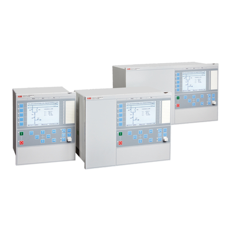
ABB RELION REX640 User manual

—
RELION® PROTECTION AND CONTROL
REX640
Technical Manual


Document ID: 1MRS759142
Issued: 2023-02-07
Revision: F
© Copyright 2023 ABB. All rights reserved

Copyright
This document and parts thereof must not be reproduced or copied without written permission from
ABB, and the contents thereof must not be imparted to a third party, nor used for any unauthorized
purpose.
The software or hardware described in this document is furnished under a license and may be used,
copied, or disclosed only in accordance with the terms of such license.
Trademarks
ABB and Relion are registered trademarks of the ABB Group. All other brand or product names
mentioned in this document may be trademarks or registered trademarks of their respective holders.
Open Source Software
This product contains open source software. For license information refer to product documentation at
www.abb.com
.
Warranty
Please inquire about the terms of warranty from your nearest ABB representative.
www.abb.com/mediumvoltage

Disclaimer
The data, examples and diagrams in this manual are included solely for the concept or product
description and are not to be deemed as a statement of guaranteed properties. All persons responsible
for applying the equipment addressed in this manual must satisfy themselves that each intended
application is suitable and acceptable, including that any applicable safety or other operational
requirements are complied with. In particular, any risks in applications where a system failure and/or
product failure would create a risk for harm to property or persons (including but not limited to
personal injuries or death) shall be the sole responsibility of the person or entity applying the
equipment, and those so responsible are hereby requested to ensure that all measures are taken to
exclude or mitigate such risks.
This product has been designed to be connected and communicate data and information via a network
interface which should be connected to a secure network. It is the sole responsibility of the person
or entity responsible for network administration to ensure a secure connection to the network and
to take the necessary measures (such as, but not limited to, installation of firewalls, application of
authentication measures, encryption of data, installation of antivirus programs, etc.) to protect the
product and the network, its system and interface included, against any kind of security breaches,
unauthorized access, interference, intrusion, leakage and/or theft of data or information. ABB is not
liable for any such damages and/or losses.
This document has been carefully checked by ABB but deviations cannot be completely ruled out. In
case any errors are detected, the reader is kindly requested to notify the manufacturer. Other than
under explicit contractual commitments, in no event shall ABB be responsible or liable for any loss or
damage resulting from the use of this manual or the application of the equipment.
In case of discrepancies between the English and any other language version, the wording of the
English version shall prevail.

Conformity
This product complies with the directive of the Council of the European Communities on the
approximation of the laws of the Member States relating to electromagnetic compatibility (EMC
Directive 2014/30/EU) and concerning electrical equipment for use within specified voltage limits
(Low-voltage directive 2014/35/EU). This conformity is the result of tests conducted by the third party
testing laboratory Intertek in accordance with the product standard EN 60255-26 for the EMC directive,
and with the product standards EN 60255-1 and EN 60255-27 for the low voltage directive. The product
is designed in accordance with the international standards of the IEC 60255 series.

Contents
1 Introduction............................................................................................. 30
1.1 This manual............................................................................................................................................ 30
1.2 Intended audience................................................................................................................................ 30
1.3 Product documentation....................................................................................................................... 31
1.3.1 Product documentation set................................................................................................ 31
1.3.2 Document revision history...................................................................................................31
1.3.3 Related documentation........................................................................................................31
1.4 Symbols and conventions.................................................................................................................... 32
1.4.1 Symbols...................................................................................................................................32
1.4.2 Document conventions........................................................................................................ 32
1.4.3 Functions, codes and symbols........................................................................................... 34
2 REX640 overview.....................................................................................42
2.1 Overview................................................................................................................................................. 42
2.1.1 PCM600 and relay connectivity package version........................................................... 42
2.2 Relay hardware.......................................................................................................................................42
2.3 Local HMI................................................................................................................................................ 45
2.4 Switchgear HMI..................................................................................................................................... 49
2.4.1 Bay overview area.................................................................................................................. 51
2.4.2 Physical and virtual Home buttons....................................................................................52
2.4.3 Navigation...............................................................................................................................52
2.5 Physical ports.........................................................................................................................................53
2.6 Web HMI.................................................................................................................................................. 53
2.7 User authorization................................................................................................................................ 55
2.7.1 Local user account management.......................................................................................55
2.7.2 Central account management............................................................................................ 55
2.8 Station communication....................................................................................................................... 56
2.9 Modification Sales................................................................................................................................ 56
3 Basic functions........................................................................................ 57
3.1 General parameters.............................................................................................................................. 57
3.1.1 Authorization settings......................................................................................................... 57
3.1.2 Binary input settings............................................................................................................58
3.1.3 Network1 address settings.................................................................................................58
3.1.4 Network2 address settings.................................................................................................58
3.1.5 HMI port address settings.................................................................................................. 58
3.1.6 System settings.....................................................................................................................59
3.1.7 HMI Settings...........................................................................................................................59
Contents
REX640
Technical Manual
7

3.1.8 HMI control settings.............................................................................................................60
3.1.9 IEC 103 Settings.....................................................................................................................61
3.1.10 IEC 103 Monitored data........................................................................................................63
3.1.11 IEC 101-104 General settings...............................................................................................63
3.1.12 IEC 101-104 Secure settings................................................................................................64
3.1.13 IEC 101-104 Secure statistics thresholds settings..........................................................65
3.1.14 IEC 101-104 Monitored data................................................................................................ 66
3.1.15 IEC 101-104 Secure monitored data...................................................................................66
3.1.16 IEC 61850-8-1 MMS settings................................................................................................67
3.1.17 MODBUS Settings.................................................................................................................68
3.1.18 MODBUS Monitored data.................................................................................................... 69
3.1.19 DNP 3.0 Settings....................................................................................................................70
3.1.20 DNP 3.0 Secure settings.......................................................................................................73
3.1.21 DNP 3.0 Secure statistics thresholds settings................................................................ 74
3.1.22 DNP 3.0 Monitored data.......................................................................................................75
3.1.23 DNP 3.0 Secure monitored data......................................................................................... 76
3.1.24 COM1 Settings....................................................................................................................... 76
3.1.25 COM1 Monitored data...........................................................................................................77
3.1.26 COM2 Settings....................................................................................................................... 77
3.1.27 COM2 Monitored data.......................................................................................................... 78
3.1.28 IO modules settings............................................................................................................. 78
3.2 Communication..................................................................................................................................... 79
3.2.1 Ethernet addresses for HMI................................................................................................80
3.2.2 Self-healing Ethernet ring................................................................................................... 80
3.2.3 Ethernet redundancy............................................................................................................80
3.2.4 Process bus............................................................................................................................ 83
3.2.5 Secure communication........................................................................................................ 85
3.2.6 Communication services control....................................................................................... 85
3.2.7 Serial port supervision SERLCCH.......................................................................................89
3.2.8 Serial port supervision SERLCCH...................................................................................... 90
3.2.9 Assigning of a serial communication protocol to a COM serial port......................... 90
3.2.10 Physical locations of the serial channels.......................................................................... 91
3.2.11 RS-485 bias and termination settings.............................................................................. 93
3.2.12 Serial link diagnostics and monitoring.............................................................................93
3.2.13 Modbus protocol MBSLPRT................................................................................................ 95
3.2.14 DNP3 protocol DNPLPRT..................................................................................................... 95
3.2.15 IEC 60870-5-103 protocol I3CLPRT.................................................................................... 96
3.2.16 IEC 60870-5-104 protocol I5CLPRT....................................................................................97
3.3 Self-supervision.....................................................................................................................................97
3.3.1 Internal faults.........................................................................................................................99
3.3.2 Warnings................................................................................................................................107
3.3.3 Power supply module Ready LED and HMI Home button LED...................................109
3.3.4 Fail-safe principle for relay protection............................................................................ 110
3.4 LED indication control LEDPTRC.......................................................................................................116
Contents
8 REX640
Technical Manual

3.4.1 Function block......................................................................................................................116
3.4.2 Functionality .........................................................................................................................117
3.5 Individual virtual LED control LED.....................................................................................................117
3.5.1 Identification.........................................................................................................................117
3.5.2 Function block.......................................................................................................................117
3.5.3 Functionality......................................................................................................................... 118
3.5.4 Signals....................................................................................................................................121
3.5.5 Settings..................................................................................................................................121
3.5.6 Monitored data.....................................................................................................................121
3.6 Time synchronization..........................................................................................................................122
3.6.1 Time master supervision GNRLLTMS.............................................................................. 122
3.7 Generic protection control PROTECTION........................................................................................131
3.7.1 Function block...................................................................................................................... 131
3.7.2 Functionality......................................................................................................................... 131
3.7.3 Signals................................................................................................................................... 134
3.7.4 Settings................................................................................................................................. 135
3.8 Local/Remote control CONTROL......................................................................................................135
3.8.1 Function block......................................................................................................................135
3.8.2 Functionality.........................................................................................................................135
3.8.3 L/R control access ..............................................................................................................136
3.8.4 Station authority level “L,R"...............................................................................................136
3.8.5 Station authority level "L,R,L+R".......................................................................................138
3.8.6 Station authority level "L,S,R" .......................................................................................... 139
3.8.7 Station authority level “L,S,S+R,L+S,L+S+R”..................................................................140
3.8.8 Control mode........................................................................................................................141
3.8.9 Signals....................................................................................................................................141
3.8.10 Settings.................................................................................................................................142
3.8.11 Monitored data....................................................................................................................143
3.9 Fault recorder FLTRFRC (ANSI FR)....................................................................................................143
3.9.1 Function block..................................................................................................................... 144
3.9.2 Functionality........................................................................................................................ 144
3.9.3 Analog channel configuration...........................................................................................145
3.9.4 Signals...................................................................................................................................146
3.9.5 Settings.................................................................................................................................146
3.9.6 Monitored data.................................................................................................................... 147
3.10 Nonvolatile memory............................................................................................................................156
3.11 Analog measurement channels........................................................................................................ 156
3.12 Sensor inputs for currents and voltages.........................................................................................157
3.13 Binary inputs........................................................................................................................................ 160
3.13.1 Binary input threshold voltage..........................................................................................161
3.13.2 Threshold hysteresis........................................................................................................... 161
3.13.3 Binary input filter time........................................................................................................161
3.13.4 Binary input inversion.........................................................................................................162
3.13.5 Oscillation suppression......................................................................................................162
Contents
REX640
Technical Manual
9
3.14 Binary outputs......................................................................................................................................163
3.14.1 Power output contacts.......................................................................................................163
3.14.2 Signal output contacts.......................................................................................................166
3.15 RTD/mA inputs/mA outputs.............................................................................................................169
3.15.1 Function blocks....................................................................................................................169
3.15.2 Functionality.........................................................................................................................169
3.15.3 Operation principle............................................................................................................. 170
3.15.4 Application............................................................................................................................ 174
3.15.5 RTD/mA input/mA output connection...........................................................................180
3.15.6 Signals................................................................................................................................... 185
3.15.7 Settings.................................................................................................................................186
3.15.8 Monitored data....................................................................................................................188
3.16 SMV function blocks........................................................................................................................... 188
3.16.1 SMV stream sender (IEC 61850-9-2LE) SMVSENDER................................................... 188
3.16.2 SMV stream receiver (IEC 61850-9-2LE) SMVRCV......................................................... 190
3.17 Preprocessing blocks.......................................................................................................................... 191
3.17.1 Phase current preprocessing ILTCTR............................................................................... 191
3.17.2 Residual current preprocessing RESTCTR...................................................................... 194
3.17.3 Phase and residual voltage preprocessing UTVTR....................................................... 197
3.17.4 Residual current preprocessing, current measured as voltage RESUTCTR.............203
3.18 GOOSE function blocks..................................................................................................................... 204
3.18.1 Received GOOSE binary information GOOSERCV_BIN................................................ 206
3.18.2 Received GOOSE double binary information GOOSERCV_DP.................................... 207
3.18.3 Received GOOSE measured value information GOOSERCV_MV................................208
3.18.4 Received GOOSE 8-bit integer value information GOOSERCV_INT8........................ 209
3.18.5 Received GOOSE 32-bit integer value information GOOSERCV_INT32.....................210
3.18.6 Received GOOSE interlocking information GOOSERCV_INTL.....................................211
3.18.7 Received GOOSE measured value (phasor) information GOOSERCV_CMV............. 212
3.18.8 Received GOOSE enumerator value information GOOSERCV_ENUM....................... 213
3.19 Type conversion function blocks......................................................................................................213
3.19.1 Good signal quality QTY_GOOD........................................................................................213
3.19.2 Bad signal quality QTY_BAD..............................................................................................214
3.19.3 Received GOOSE test mode QTY_GOOSE_TEST........................................................... 215
3.19.4 GOOSE communication quality QTY_GOOSE_COMM.................................................. 215
3.19.5 GOOSE data health T_HEALTH..........................................................................................216
3.19.6 Fault direction evaluation T_DIR.......................................................................................218
3.19.7 Fault direction evaluation T_DIR_FWD............................................................................ 219
3.19.8 Fault direction evaluation T_DIR_REV.............................................................................220
3.19.9 Enumerator to boolean conversion T_TCMD..................................................................221
3.19.10 32-bit integer to binary command conversion T_TCMD_BIN......................................222
3.19.11 Binary command to 32-bit integer conversion T_BIN_TCMD......................................223
3.19.12 Integer 32-bit to real conversion T_I32_TO_R................................................................ 224
3.19.13 Real to integer 8-bit conversion T_R_TO_I8................................................................... 225
3.19.14 Real to integer 32-bit conversion T_R_TO_I32............................................................... 226
Contents
10 REX640
Technical Manual

3.19.15 Integer 32-bit switch selector SWITCHI32...................................................................... 227
3.19.16 Integer 32-bit to boolean conversion T_I32_TO_B16.................................................... 228
3.19.17 Boolean to integer 32-bit conversion T_B16_TO_I32.................................................... 229
3.19.18 Integer 8-bit to integer 32-bit conversion T_I8_TO_I32............................................... 230
3.20 Configurable logic blocks.................................................................................................................. 231
3.20.1 Minimum pulse timer..........................................................................................................231
3.20.2 Pulse timer, eight channels PTGAPC (ANSI 62PT).........................................................235
3.20.3 Daily timer DTMGAPC (ANSI DTM)................................................................................... 237
3.20.4 Calendar function CALGAPC (ANSI CAL).........................................................................241
3.20.5 Time delay off, eight channels TOFGAPC (ANSI 62TOF)..............................................244
3.20.6 Time delay on, eight channels TONGAPC (ANSI 62TON).............................................246
3.20.7 SR flip-flop, eight channels, nonvolatile SRGAPC (ANSI SR)....................................... 249
3.20.8 Boolean value event creation MVGAPC (ANSI MV)........................................................ 251
3.20.9 Integer value event creation MVI4GAPC (ANSI MVI4)...................................................253
3.20.10 Analog value event creation with scaling SCA4GAPC (ANSI SCA4)...........................254
3.20.11 16 settable real values SETRGAPC....................................................................................255
3.20.12 16 settable 32-bit integer values SETI32GAPC...............................................................257
3.20.13 Generic control points SPCGAPC (ANSI SPCG)..............................................................259
3.20.14 Pulse counter for energy measurement PCGAPC......................................................... 265
3.20.15 Hotline tag HLTGAPC.......................................................................................................... 271
3.20.16 Voltage switch VMSWI (ANSI VSWI)................................................................................. 274
3.20.17 Current switch CMSWI .......................................................................................................278
3.20.18 Generic up-down counter UDFCNT..................................................................................281
3.20.19 Current sum CMSUM (ANSI CSUM) .................................................................................283
3.20.20 Transformer data combiner OLGAPC............................................................................. 285
3.20.21 Controllable gate, 8 channels GATEGAPC.......................................................................287
3.21 Standard logic operators.................................................................................................................. 289
3.21.1 OR gate with two inputs OR, six inputs OR6 and twenty inputs OR20....................289
3.21.2 AND gate with two inputs AND, six inputs AND6 and twenty inputs AND20..........291
3.21.3 XOR gate with two inputs XOR.........................................................................................293
3.21.4 NOT gate NOT...................................................................................................................... 293
3.21.5 Rising edge detector R_TRIG............................................................................................294
3.21.6 Falling edge detector F_TRIG............................................................................................295
3.21.7 Switching device status decoder CLOSE position T_POS_CL, OPEN position
T_POS_OP and OK status T_POS_OK.........................................................................296
3.21.8 SR flip-flop, volatile SR....................................................................................................... 297
3.21.9 RS flip-flop, volatile RS....................................................................................................... 298
3.22 Mathematical operators.................................................................................................................... 299
3.22.1 Real addition ADDR.............................................................................................................299
3.22.2 Real division DIVR............................................................................................................... 300
3.22.3 Real multiplication MULR...................................................................................................301
3.22.4 Real subtraction SUBR....................................................................................................... 302
3.22.5 Real equal comparator EQR.............................................................................................. 302
3.22.6 Real not equal comparator NER.......................................................................................304
Contents
REX640
Technical Manual
11

3.22.7 Real greater than or equal comparator GER..................................................................305
3.22.8 Real less than or equal comparator LER.........................................................................306
3.22.9 Real maximum value selector MAX3R............................................................................. 307
3.22.10 Real minimum value selector MIN3R...............................................................................308
3.22.11 Real switch selector SWITCHR......................................................................................... 309
3.22.12 Integer 32-bit switch selector SWITCHI32......................................................................310
3.23 Factory settings restoration............................................................................................................. 310
3.24 Load profile LDPRLRC (ANSI LOADPROF)....................................................................................... 311
3.24.1 Identification........................................................................................................................ 311
3.24.2 Function block...................................................................................................................... 311
3.24.3 Functionality......................................................................................................................... 311
3.24.4 Configuration.......................................................................................................................314
3.24.5 Signals................................................................................................................................... 314
3.24.6 LDPRLRC Settings............................................................................................................... 315
3.24.7 LDPRLRC Monitored data.................................................................................................. 315
3.25 Ethernet channel supervision functions.........................................................................................315
3.25.1 Redundant Ethernet channel supervision RCHLCCH................................................... 315
3.25.2 Ethernet channel supervision SCHLCCH.........................................................................317
3.26 External HMI wake-up EIHMI.............................................................................................................320
3.26.1 Function block .................................................................................................................... 320
3.26.2 Functionality........................................................................................................................ 320
3.26.3 Operation principle.............................................................................................................320
3.26.4 Application............................................................................................................................321
3.26.5 Signals................................................................................................................................... 322
3.26.6 Settings.................................................................................................................................322
3.26.7 Monitored data....................................................................................................................322
3.27 HMI Ethernet channel supervision HMILCCH.................................................................................323
3.27.1 Function block......................................................................................................................323
3.27.2 Functionality.........................................................................................................................323
3.27.3 Signals................................................................................................................................... 323
3.27.4 Settings.................................................................................................................................324
3.27.5 Monitored data....................................................................................................................324
3.28 Line differential communication port supervision SCHLCCH6................................................. 324
3.28.1 Function block..................................................................................................................... 324
3.28.2 Functionality........................................................................................................................ 324
3.28.3 Signals...................................................................................................................................324
3.28.4 Monitored data....................................................................................................................325
3.28.5 Diagnostics...........................................................................................................................325
4 Protection functions.............................................................................326
4.1 Three-phase current protection.......................................................................................................326
4.1.1 Three-phase non-directional overcurrent protection PHxPTOC (ANSI 51P-1,
51P-2, 50P).......................................................................................................................326
Contents
12 REX640
Technical Manual

4.1.2 Three-phase directional overcurrent protection DPHxPDOC (ANSI 67P/51P-1,
67P/51P-2)....................................................................................................................... 344
4.1.3 Three-phase voltage-dependent overcurrent protection PHPVOC (ANSI 51V)...... 369
4.1.4 Accidental energization protection GAEPVOC (ANSI 27/50)......................................378
4.1.5 Three-phase thermal protection for feeders, cables and distribution
transformers T1PTTR (ANSI 49F)................................................................................383
4.1.6 Three-phase thermal overload protection, two time constants T2PTTR (ANSI
49T/G/C)......................................................................................................................... 389
4.1.7 Motor load jam protection JAMPTOC (ANSI 50TDJAM).............................................. 398
4.1.8 Loss of load supervision LOFLPTUC (ANSI 37)............................................................. 402
4.1.9 Loss of phase, undercurrent PHPTUC (ANSI 37)...........................................................405
4.1.10 Thermal overload protection for motors MPTTR (ANSI 49M).................................... 410
4.1.11 Thermal overload protection for rotors RPTTR (ANSI 49R)........................................423
4.1.12 Generator shaft current leakage protection GSLPTOC ( ANSI 38,51)....................... 435
4.2 Earth-fault protection....................................................................................................................... 440
4.2.1 Non-directional earth-fault protection EFxPTOC (ANSI 51G/51N-1, 51G/51N-2,
50G/50N)........................................................................................................................440
4.2.2 Directional earth-fault protection DEFxPDEF (ANSI 67G/N-1 51G/N-1, 67G/N-1
51G/N-2).......................................................................................................................... 451
4.2.3 Transient-intermittent earth-fault protection INTRPTEF (ANSI 67NTEF/NIEF)..... 482
4.2.4 Admittance-based earth-fault protection EFPADM (ANSI 21NY)..............................490
4.2.5 Rotor earth-fault protection, injection method MREFPTOC (ANSI 64R)..................515
4.2.6 Harmonics-based earth-fault protection HAEFPTOC (ANSI 51NH)...........................521
4.2.7 Wattmetric-based earth-fault protection WPWDE (ANSI 32N).................................. 529
4.2.8 Third harmonic based stator earth-fault protection H3EFPSEF (ANSI 64TN)........ 541
4.2.9 Multifrequency admittance-based earth-fault protection MFADPSDE (ANSI
67NYH).............................................................................................................................553
4.2.10 Touch voltage based earth-fault current protection IFPTOC (ANSI 46SNQ/59N). 582
4.3 Differential protection....................................................................................................................... 643
4.3.1 Line differential protection with in-zone power transformer LNPLDF (ANSI 87L) 643
4.3.2 Stabilized and instantaneous differential protection for two-winding
transformers TR2PTDF (ANSI 87T)............................................................................ 680
4.3.3 Stabilized and instantaneous differential protection for two- or three-winding
transformers TR3PTDF (ANSI 87T3)........................................................................... 716
4.3.4 Numerically stabilized low-impedance restricted earth-fault protection
LREFPNDF (ANSI 87NLI)................................................................................................748
4.3.5 High-impedance based restricted earth-fault protection HREFPDIF (ANSI
87NHI)...............................................................................................................................759
4.3.6 High-impedance differential protection HIxPDIF (ANSI 87_A, 87_B, 87_C)..............772
4.3.7 Stabilized and instantaneous differential protection for machines MPDIF
(ANSI 87M/87G)..............................................................................................................788
4.3.8 High-impedance or flux-balance based differential protection MHZPDIF (ANSI
87HIM)............................................................................................................................. 806
4.4 Unbalance protection.........................................................................................................................819
Contents
REX640
Technical Manual
13

4.4.1 Negative-sequence overcurrent protection NSPTOC (ANSI 46M)............................. 819
4.4.2 Directional negative-sequence overcurrent protection DNSPDOC (ANSI 67Q)......825
4.4.3 Phase discontinuity protection PDNSPTOC (ANSI 46PD)........................................... 832
4.4.4 Phase reversal protection PREVPTOC (ANSI 46R).........................................................837
4.4.5 Negative-sequence overcurrent protection for machines MNSPTOC (ANSI 46M).841
4.5 Voltage protection..............................................................................................................................850
4.5.1 Three-phase overvoltage protection PHPTOV (ANSI 59)............................................ 850
4.5.2 Three-phase undervoltage protection PHPTUV (ANSI 27)..........................................858
4.5.3 Residual overvoltage protection ROVPTOV (ANSI 59G/ 59N)....................................866
4.5.4 Positive-sequence overvoltage protection PSPTOV (ANSI 59PS)..............................870
4.5.5 Negative-sequence overvoltage protection NSPTOV (ANSI 59NS)........................... 875
4.5.6 Positive-sequence undervoltage protection PSPTUV (ANSI 27PS)............................879
4.5.7 Overexcitation protection OEPVPH (ANSI 24)...............................................................884
4.5.8 Low-voltage ride-through protection LVRTPTUV (ANSI 27RT).................................. 900
4.5.9 Voltage vector shift protection VVSPPAM (ANSI 78VS)...............................................908
4.5.10 Three-phase overvoltage variation protection PHVPTOV (ANSI 59.S1) ................... 913
4.6 Frequency protection.........................................................................................................................920
4.6.1 Frequency protection FRPFRQ (ANSI 81)....................................................................... 920
4.6.2 Load-shedding and restoration LSHDPFRQ (ANSI 81LSH).........................................928
4.7 Impedance protection....................................................................................................................... 940
4.7.1 Distance protection DSTPDIS (ANSI 21P, 21N)...............................................................940
4.7.2 Out of step OOSRPSB (ANSI 78PS)................................................................................1005
4.7.3 Three-phase underexcitation protection UEXPDIS (ANSI 40).................................. 1015
4.7.4 Three-phase underimpedance protection UZPDIS (ANSI 21G) ............................... 1026
4.7.5 Directional negative sequence impedance protection DNZPDIS (ANSI Z2Q)....... 1038
4.7.6 Power swing detection DSTRPSB (ANSI 68)................................................................1046
4.8 Power protection...............................................................................................................................1055
4.8.1 Underpower protection DUPPDPR (ANSI 32U)............................................................1055
4.8.2 Reverse power-directional overpower protection DOPPDPR (ANSI 32R/32O)..... 1062
4.8.3 Directional reactive power undervoltage protection DQPTUV (ANSI 32Q,27).......1071
4.8.4 Underpower factor protection MPUPF (ANSI 55U).....................................................1078
4.9 Arc protection ARCSARC (ANSI AFD).............................................................................................1085
4.9.1 Identification..................................................................................................................... 1085
4.9.2 Function block................................................................................................................... 1085
4.9.3 Functionality...................................................................................................................... 1085
4.9.4 Analog channel configuration........................................................................................ 1085
4.9.5 Operation principle.......................................................................................................... 1086
4.9.6 Application..........................................................................................................................1087
4.9.7 Signals................................................................................................................................. 1091
4.9.8 ARCSARC Settings.............................................................................................................1092
4.9.9 ARCSARC Monitored data................................................................................................1092
4.9.10 Technical data ................................................................................................................... 1093
4.10 Motor start-up supervision STTPMSU (ANSI 49,66,48,50TDLR)............................................. 1093
4.10.1 Identification......................................................................................................................1093
Contents
14 REX640
Technical Manual

4.10.2 Function block................................................................................................................... 1093
4.10.3 Functionality...................................................................................................................... 1094
4.10.4 Analog input configuration.............................................................................................1094
4.10.5 Operation principle...........................................................................................................1095
4.10.6 Application......................................................................................................................... 1099
4.10.7 Signals..................................................................................................................................1102
4.10.8 STTPMSU Settings.............................................................................................................1103
4.10.9 STTPMSU Monitored data............................................................................................... 1104
4.10.10 Technical data ................................................................................................................... 1105
4.10.11 Technical revision history................................................................................................ 1105
4.11 Multipurpose protection MAPGAPC (ANSI MAP).........................................................................1105
4.11.1 Identification......................................................................................................................1105
4.11.2 Function block....................................................................................................................1105
4.11.3 Functionality.......................................................................................................................1106
4.11.4 Operation principle...........................................................................................................1106
4.11.5 Application.......................................................................................................................... 1107
4.11.6 Signals................................................................................................................................. 1108
4.11.7 MAPGAPC Settings............................................................................................................1108
4.11.8 MAPGAPC Monitored data...............................................................................................1109
4.11.9 Technical data ................................................................................................................... 1109
4.12 Capacitor bank protection.............................................................................................................. 1109
4.12.1 Three-phase overload protection for shunt capacitor banks COLPTOC (ANSI
51,37,86C).......................................................................................................................1109
4.12.2 Current unbalance protection for capacitor banks CUBPTOC (ANSI 60N).............1119
4.12.3 Three-phase current unbalance protection for shunt capacitor banks
HCUBPTOC (ANSI 60P)................................................................................................ 1131
4.12.4 Shunt capacitor bank switching resonance protection, current based,
SRCPTOC (ANSI 55ITHD).............................................................................................1142
4.12.5 Compensated neutral unbalance voltage protection CNUPTOV (ANSI 59NU)......1148
5 Protection related functions..............................................................1157
5.1 Three-phase inrush detector INRPHAR (ANSI 68HB).................................................................. 1157
5.1.1 Identification...................................................................................................................... 1157
5.1.2 Function block....................................................................................................................1157
5.1.3 Functionality.......................................................................................................................1157
5.1.4 Analog channel configuration......................................................................................... 1157
5.1.5 Operation principle........................................................................................................... 1158
5.1.6 Application..........................................................................................................................1159
5.1.7 Signals................................................................................................................................. 1160
5.1.8 INRPHAR Settings.............................................................................................................. 1161
5.1.9 INRPHAR Monitored data................................................................................................. 1161
5.1.10 Technical data ....................................................................................................................1161
5.2 Circuit breaker failure protection CCBRBRF (ANSI 50BF).......................................................... 1162
5.2.1 Identification...................................................................................................................... 1162
Contents
REX640
Technical Manual
15

5.2.2 Function block.................................................................................................................... 1162
5.2.3 Functionality.......................................................................................................................1162
5.2.4 Analog channel configuration......................................................................................... 1163
5.2.5 Operation principle........................................................................................................... 1163
5.2.6 Application...........................................................................................................................1171
5.2.7 Signals.................................................................................................................................. 1172
5.2.8 CCBRBRF Settings..............................................................................................................1173
5.2.9 CCBRBRF Monitored data.................................................................................................1174
5.2.10 Technical data ....................................................................................................................1174
5.2.11 Technical revision history.................................................................................................1174
5.3 Master trip TRPPTRC (ANSI 94/86)................................................................................................ 1175
5.3.1 Identification...................................................................................................................... 1175
5.3.2 Function block.................................................................................................................... 1175
5.3.3 Functionality....................................................................................................................... 1175
5.3.4 Operation principle............................................................................................................1175
5.3.5 Application.......................................................................................................................... 1176
5.3.6 Signals.................................................................................................................................. 1177
5.3.7 TRPPTRC Settings..............................................................................................................1178
5.3.8 TRPPTRC Monitored data.................................................................................................1178
5.4 High-impedance fault detection PHIZ (ANSI HIZ)....................................................................... 1179
5.4.1 Identification...................................................................................................................... 1179
5.4.2 Function block.................................................................................................................... 1179
5.4.3 Functionality....................................................................................................................... 1179
5.4.4 Analog channel configuration......................................................................................... 1179
5.4.5 Operation principle...........................................................................................................1180
5.4.6 Application..........................................................................................................................1182
5.4.7 Signals..................................................................................................................................1182
5.4.8 PHIZ Settings......................................................................................................................1183
5.4.9 PHIZ Monitored data.........................................................................................................1183
5.5 Binary signal transfer BSTGAPC (ANSI BST).................................................................................1184
5.5.1 Identification......................................................................................................................1184
5.5.2 Function block....................................................................................................................1184
5.5.3 Functionality.......................................................................................................................1184
5.5.4 Operation principle........................................................................................................... 1185
5.5.5 Application..........................................................................................................................1186
5.5.6 Signals..................................................................................................................................1187
5.5.7 Settings............................................................................................................................... 1188
5.5.8 Technical data ................................................................................................................... 1189
5.6 Emergency start-up ESMGAPC (ANSI EST,62)..............................................................................1190
5.6.1 Identification......................................................................................................................1190
5.6.2 Function block....................................................................................................................1190
5.6.3 Functionality.......................................................................................................................1190
5.6.4 Analog channel configuration.........................................................................................1190
5.6.5 Operation principle............................................................................................................1191
Contents
16 REX640
Technical Manual

5.6.6 Application.......................................................................................................................... 1191
5.6.7 Signals..................................................................................................................................1192
5.6.8 ESMGAPC Settings............................................................................................................ 1192
5.6.9 ESMGAPC Monitored data............................................................................................... 1192
5.6.10 Technical data ....................................................................................................................1193
5.6.11 Technical revision history.................................................................................................1193
5.7 Fault locator SCEFRFLO (ANSI FLOC)............................................................................................ 1193
5.7.1 Identification...................................................................................................................... 1193
5.7.2 Function block.................................................................................................................... 1193
5.7.3 Functionality.......................................................................................................................1194
5.7.4 Analog channel configuration.........................................................................................1194
5.7.5 Operation principle........................................................................................................... 1195
5.7.6 Measurement modes........................................................................................................ 1216
5.7.7 Application.......................................................................................................................... 1217
5.7.8 Signals..................................................................................................................................1218
5.7.9 SCEFRFLO Settings...........................................................................................................1218
5.7.10 SCEFRFLO Monitored data..............................................................................................1220
5.7.11 Technical data ................................................................................................................... 1222
5.8 Switch-onto-fault protection CVPSOF (ANSI SOTF)...................................................................1222
5.8.1 Identification......................................................................................................................1222
5.8.2 Function block....................................................................................................................1222
5.8.3 Functionality.......................................................................................................................1223
5.8.4 Analog channel configuration.........................................................................................1223
5.8.5 Operation principle...........................................................................................................1224
5.8.6 Application..........................................................................................................................1226
5.8.7 Signals..................................................................................................................................1227
5.8.8 CVPSOF Settings...............................................................................................................1228
5.8.9 CVPSOF Monitored data.................................................................................................. 1229
5.8.10 Technical data....................................................................................................................1230
5.9 Local acceleration logic DSTPLAL (ANSI 21LAL)..........................................................................1230
5.9.1 Identification......................................................................................................................1230
5.9.2 Function block................................................................................................................... 1230
5.9.3 Functionality...................................................................................................................... 1230
5.9.4 Analog channel configuration......................................................................................... 1231
5.9.5 Operation principle........................................................................................................... 1231
5.9.6 Application..........................................................................................................................1234
5.9.7 Signals................................................................................................................................. 1235
5.9.8 DSTPLAL Settings............................................................................................................. 1235
5.9.9 DSTPLAL Monitored data................................................................................................ 1236
5.9.10 Technical data.................................................................................................................... 1236
5.10 Scheme communication logic DSOCPSCH (ANSI 85 21SCHLGC).............................................1236
5.10.1 Identification......................................................................................................................1236
5.10.2 Function block....................................................................................................................1237
5.10.3 Functionality.......................................................................................................................1237
Contents
REX640
Technical Manual
17

5.10.4 Operation principle........................................................................................................... 1237
5.10.5 Application......................................................................................................................... 1244
5.10.6 Signals.................................................................................................................................1248
5.10.7 DSOCPSCH Settings.........................................................................................................1250
5.10.8 DSOCPSCH Monitored data............................................................................................1250
5.10.9 Technical data....................................................................................................................1250
5.11 Communication logic for residual overcurrent RESCPSCH (ANSI 85 67G/N SCHLGC)........ 1251
5.11.1 Identification...................................................................................................................... 1251
5.11.2 Function block....................................................................................................................1251
5.11.3 Functionality.......................................................................................................................1251
5.11.4 Operation principle........................................................................................................... 1252
5.11.5 Application......................................................................................................................... 1258
5.11.6 Signals................................................................................................................................. 1262
5.11.7 RESCPSCH Settings..........................................................................................................1264
5.11.8 RESCPSCH Monitored data.............................................................................................1264
5.11.9 Technical data....................................................................................................................1264
5.12 Current reversal and weak-end infeed logic CRWPSCH (ANSI 85 21CREV,WEI).................... 1265
5.12.1 Identification......................................................................................................................1265
5.12.2 Function block................................................................................................................... 1265
5.12.3 Functionality...................................................................................................................... 1265
5.12.4 Analog channel configuration........................................................................................ 1266
5.12.5 Operation principle...........................................................................................................1266
5.12.6 Application......................................................................................................................... 1269
5.12.7 Signals..................................................................................................................................1271
5.12.8 CRWPSCH Settings............................................................................................................1272
5.12.9 CRWPSCH Monitored data...............................................................................................1272
5.12.10 Technical data.................................................................................................................... 1273
5.13 Current reversal and weak-end infeed logic for residual overcurrent RCRWPSCH (ANSI
85 67G/N CREV,WEI).................................................................................................................... 1274
5.13.1 Identification......................................................................................................................1274
5.13.2 Function block....................................................................................................................1274
5.13.3 Functionality.......................................................................................................................1274
5.13.4 Analog channel configuration.........................................................................................1274
5.13.5 Operation principle........................................................................................................... 1275
5.13.6 Application..........................................................................................................................1277
5.13.7 Signals................................................................................................................................. 1279
5.13.8 RCRWPSCH Settings.........................................................................................................1280
5.13.9 RCRWPSCH Monitored data............................................................................................1280
5.13.10 Technical data.................................................................................................................... 1281
5.14 Three-phase power directional element DPSRDIR (ANSI 67P-TC)............................................1281
5.14.1 Identification......................................................................................................................1281
5.14.2 Function block....................................................................................................................1281
5.14.3 Functionality.......................................................................................................................1281
5.14.4 Analog channel configuration.........................................................................................1282
Contents
18 REX640
Technical Manual

5.14.5 Operation principle...........................................................................................................1282
5.14.6 Application......................................................................................................................... 1284
5.14.7 Signals.................................................................................................................................1284
5.14.8 DPSRDIR Settings..............................................................................................................1284
5.14.9 DPSRDIR Monitored data.................................................................................................1285
5.15 Neutral power directional element DNZSRDIR (ANSI 67N-TC)................................................. 1285
5.15.1 Identification......................................................................................................................1285
5.15.2 Function block................................................................................................................... 1286
5.15.3 Functionality...................................................................................................................... 1286
5.15.4 Analog channel configuration........................................................................................ 1286
5.15.5 Operation principle........................................................................................................... 1287
5.15.6 Application..........................................................................................................................1292
5.15.7 Signals................................................................................................................................. 1292
5.15.8 DNZSRDIR Settings........................................................................................................... 1293
5.15.9 DNZSRDIR Monitored data..............................................................................................1294
5.16 Load blinder LBRDOB (ANSI 21LB)................................................................................................. 1294
5.16.1 Identification......................................................................................................................1294
5.16.2 Function block................................................................................................................... 1294
5.16.3 Functionality...................................................................................................................... 1294
5.16.4 Analog channel configuration.........................................................................................1295
5.16.5 Operation principle...........................................................................................................1295
5.16.6 Application..........................................................................................................................1297
5.16.7 Signals................................................................................................................................. 1299
5.16.8 Settings...............................................................................................................................1299
5.16.9 Monitored data..................................................................................................................1300
5.16.10 Technical data....................................................................................................................1300
6 Supervision functions.........................................................................1302
6.1 Trip circuit supervision TCSSCBR (ANSI TCM).............................................................................1302
6.1.1 Identification......................................................................................................................1302
6.1.2 Function block................................................................................................................... 1302
6.1.3 Functionality...................................................................................................................... 1302
6.1.4 Operation principle...........................................................................................................1302
6.1.5 Application..........................................................................................................................1303
6.1.6 Signals.................................................................................................................................1309
6.1.7 TCSSCBR Settings............................................................................................................. 1310
6.1.8 TCSSCBR Monitored data................................................................................................ 1310
6.2 Current circuit supervision CCSPVC (ANSI CCM).........................................................................1310
6.2.1 Identification......................................................................................................................1310
6.2.2 Function block....................................................................................................................1310
6.2.3 Functionality.......................................................................................................................1310
6.2.4 Analog channel configuration..........................................................................................1311
6.2.5 Operation principle............................................................................................................1311
6.2.6 Application..........................................................................................................................1313
Contents
REX640
Technical Manual
19

6.2.7 Signals.................................................................................................................................. 1317
6.2.8 CCSPVC Settings................................................................................................................1318
6.2.9 CCSPVC Monitored data...................................................................................................1318
6.2.10 Technical data ....................................................................................................................1318
6.2.11 Technical revision history.................................................................................................1318
6.3 Current transformer supervision for high-impedance protection scheme HZCCxSPVC
(ANSI CCM_A, CCM_B, CCM_C).................................................................................................. 1319
6.3.1 Identification...................................................................................................................... 1319
6.3.2 Function block....................................................................................................................1319
6.3.3 Functionality....................................................................................................................... 1319
6.3.4 Analog channel configuration.........................................................................................1320
6.3.5 Operation principle...........................................................................................................1320
6.3.6 Measuring modes.............................................................................................................. 1321
6.3.7 Application..........................................................................................................................1322
6.3.8 Signals................................................................................................................................. 1323
6.3.9 Settings...............................................................................................................................1324
6.3.10 Monitored data.................................................................................................................. 1325
6.3.11 Technical data ................................................................................................................... 1326
6.4 Protection communication supervision PCSITPC (ANSI PCS) .................................................1326
6.4.1 Identification......................................................................................................................1326
6.4.2 Function block....................................................................................................................1327
6.4.3 Functionality.......................................................................................................................1327
6.4.4 Operation principle........................................................................................................... 1327
6.4.5 Application..........................................................................................................................1328
6.4.6 Signals................................................................................................................................. 1330
6.4.7 PCSITPC Settings.............................................................................................................. 1330
6.4.8 PCSITPC Monitored data................................................................................................. 1330
6.5 Fuse failure supervision SEQSPVC (ANSI VCM, 60).....................................................................1331
6.5.1 Identification...................................................................................................................... 1331
6.5.2 Function block....................................................................................................................1331
6.5.3 Functionality....................................................................................................................... 1331
6.5.4 Analog channel configuration......................................................................................... 1331
6.5.5 Operation principle........................................................................................................... 1332
6.5.6 Application..........................................................................................................................1335
6.5.7 Signals................................................................................................................................. 1336
6.5.8 SEQSPVC Settings.............................................................................................................1337
6.5.9 SEQSPVC Monitored data................................................................................................1338
6.5.10 Technical data ................................................................................................................... 1338
6.6 Runtime counter for machines and devices MDSOPT (ANSI OPTM).......................................1339
6.6.1 Identification......................................................................................................................1339
6.6.2 Function block....................................................................................................................1339
6.6.3 Functionality.......................................................................................................................1339
6.6.4 Operation principle...........................................................................................................1339
6.6.5 Application......................................................................................................................... 1340
Contents
20 REX640
Technical Manual
Other manuals for RELION REX640
9
Table of contents
Other ABB Control Unit manuals

ABB
ABB CP1484 User manual

ABB
ABB TCC300 User manual

ABB
ABB i-bus EIB User manual

ABB
ABB ACS880-204LC User manual

ABB
ABB NCSA-01 CS 31 Installation manual

ABB
ABB MRP31.0 User manual

ABB
ABB FPTC-01 User manual

ABB
ABB RELION Series User manual

ABB
ABB RET615 User manual

ABB
ABB COM600 series 5.0 Instruction Manual

ABB
ABB ret650 Quick start guide

ABB
ABB MOD 30ML User manual

ABB
ABB ACS850-04 series Use and care manual

ABB
ABB RPBA-01 User manual

ABB
ABB SACE PR212/D-M User manual

ABB
ABB OMD800 User guide

ABB
ABB LW 110 User manual

ABB
ABB Ability 800xA Series User manual

ABB
ABB FDNA-01 Installation manual

ABB
ABB ACQ580-04 User manual