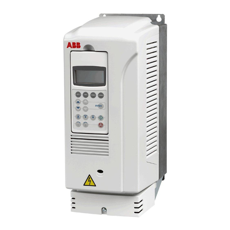
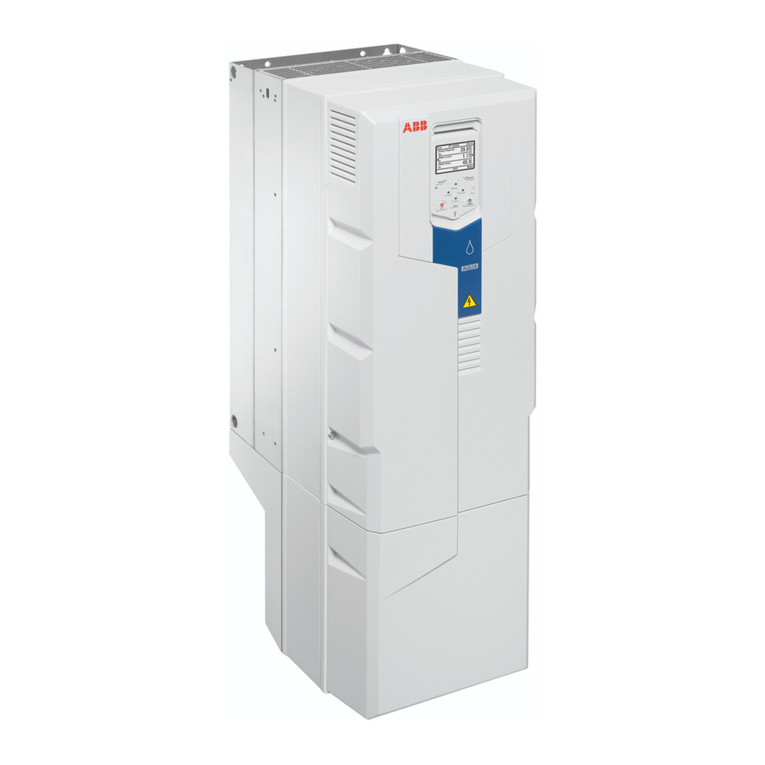
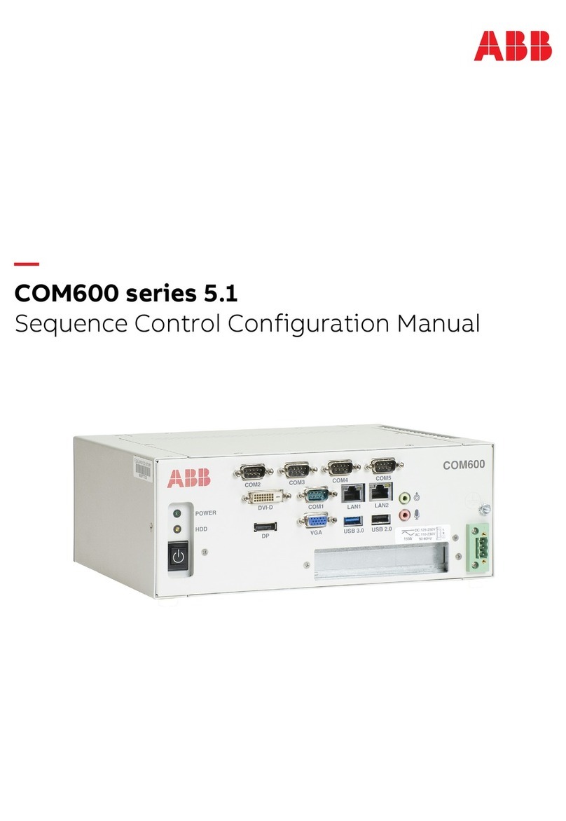
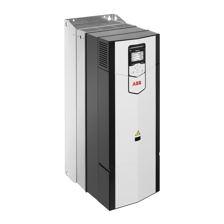
ABB ACS880 Series User manual

—
ABB INDUSTRIAL DRIVES
ACS880 primary control program
Firmware manual


Table of contents
1 Introduction to the manual
15What this chapter contains .................................................................................
15Applicability .........................................................................................................
15Safety instructions ...............................................................................................
15Target audience ..................................................................................................
16Related manuals .................................................................................................
17Terms and abbreviations .....................................................................................
19Cybersecurity disclaimer .....................................................................................
2 Using the control panel
3 Control locations and operating modes
23What this chapter contains .................................................................................
23Local control vs. external control ........................................................................
24Local control .................................................................................................
25External control ............................................................................................
25Using the control panel as an external control source ......................
26Operating modes of the drive .............................................................................
26Speed control mode .....................................................................................
27Torque control mode ....................................................................................
27Frequency control mode ..............................................................................
27DC voltage control mode .............................................................................
27Special control modes ..................................................................................
4 Program features
29What this chapter contains .................................................................................
30Drive configuration and programming .................................................................
30Programming via parameters .......................................................................
31Adaptive programming .................................................................................
31Settings and diagnostics ...................................................................
31Application programming .............................................................................
32Control interfaces ................................................................................................
32Programmable analog inputs .......................................................................
32Settings and diagnostics ...................................................................
32Programmable analog outputs .....................................................................
32Settings and diagnostics ...................................................................
32Programmable digital inputs and outputs .....................................................
33Settings and diagnostics ...................................................................
Table of contents 5

33Programmable relay outputs ........................................................................
33Settings and diagnostics ...................................................................
33Programmable I/O extensions .....................................................................
34Settings and diagnostics ...................................................................
34Fieldbus control ............................................................................................
34Settings and diagnostics ...................................................................
34Master/follower functionality .........................................................................
34General .............................................................................................
36Load share function with a speed-controlled follower .......................
36Communication .................................................................................
38Construction of the master/follower link ............................................
40Example parameter settings .............................................................
41Specifications of the fiber optic master/follower link .........................
42Settings and diagnostics ...................................................................
42External controller interface .........................................................................
42General .............................................................................................
42Topology ...........................................................................................
44Communication .................................................................................
45Control of a supply unit (LSU) ......................................................................
45General .............................................................................................
45Communication .................................................................................
46Settings and diagnostics ...................................................................
46Motor control .......................................................................................................
46Direct torque control (DTC) ..........................................................................
46Settings and diagnostics ...................................................................
47Reference ramping ......................................................................................
47Special acceleration/deceleration ramps ..........................................
47Settings and diagnostics ...................................................................
48Constant speeds/frequencies ......................................................................
48Settings and diagnostics ...................................................................
48Critical speeds/frequencies ..........................................................................
48Example ............................................................................................
49Settings and diagnostics ...................................................................
49Speed controller autotune ............................................................................
50Before activating the autotune routine ..............................................
51Autotune modes ................................................................................
51Autotune results ................................................................................
52Warning indications ..........................................................................
52Settings and diagnostics ...................................................................
52Oscillation damping ......................................................................................
53Tuning procedure for oscillation damping .........................................
53Settings and diagnostics ...................................................................
53Resonance frequency elimination ................................................................
53Settings and diagnostics ...................................................................
6 Table of contents

54Rush control .................................................................................................
54Settings and diagnostics ...................................................................
54Encoder support ...........................................................................................
55Encoder echo and emulation ............................................................
55Load and motor feedback .................................................................
56Position counter ................................................................................
57Encoder error handling .....................................................................
58Reading/writing position counter values through fieldbus ................
58Configuration of HTL encoder motor feedback .................................
59
Example 1: Using the same encoder for both load and motor
feedback ...........................................................................................
59Example 2: Using two encoders .......................................................
60Example 3: ACS 600 / ACS800 compatibility ...................................
61Settings and diagnostics ...................................................................
61Jogging .........................................................................................................
63Settings and diagnostics ...................................................................
63Scalar motor control .....................................................................................
64IR compensation for scalar motor control .........................................
64Settings and diagnostics ...................................................................
64Autophasing .................................................................................................
66Autophasing modes ..........................................................................
67Settings and diagnostics ...................................................................
67Flux braking ..................................................................................................
68Settings and diagnostics ...................................................................
68DC magnetization .........................................................................................
68Pre-heating .......................................................................................
68Pre-magnetization .............................................................................
68DC hold .............................................................................................
69Post-magnetization ...........................................................................
69Continuous magnetization ................................................................
70Settings and diagnostics ...................................................................
70Motor temperature estimation ......................................................................
70Settings and diagnostics ...................................................................
70Hexagonal motor flux pattern .......................................................................
71Settings and diagnostics ...................................................................
72Application control ...............................................................................................
72Application macros .......................................................................................
72Process PID control .....................................................................................
72Quick configuration of the process PID controller ............................
73Sleep function for process PID control .............................................
74Tracking ............................................................................................
74Settings and diagnostics ...................................................................
75Motor potentiometer .....................................................................................
75Settings and diagnostics ...................................................................
Table of contents 7

76Mechanical brake control .............................................................................
76Inputs of the brake control logic ........................................................
76Outputs of the brake control logic .....................................................
77Brake state diagram ..........................................................................
79Timing diagram .................................................................................
80Wiring example .................................................................................
81Settings and diagnostics ...................................................................
81DC voltage control ..............................................................................................
81Overvoltage control ......................................................................................
81Undervoltage control (power loss ride-through) ...........................................
82Automatic restart ...............................................................................
83Settings and diagnostics ...................................................................
83Voltage control and trip limits .......................................................................
83Settings and diagnostics ...................................................................
84Brake chopper ..............................................................................................
84Settings and diagnostics ...................................................................
84DC voltage boost ..........................................................................................
84Description of the DC voltage boost function ...................................
85Use case examples ..........................................................................
86Limits ................................................................................................
88DC voltage control mode .............................................................................
88Settings and diagnostics ...................................................................
89Safety and protections ........................................................................................
89Emergency stop ...........................................................................................
89Settings and diagnostics ...................................................................
90Motor thermal protection ..............................................................................
90Motor thermal protection model ........................................................
90Temperature monitoring using PTC sensors ....................................
92Temperature monitoring using Pt100 or Pt1000 sensors .................
92Temperature monitoring using KTY84 sensors ................................
93Motor fan control logic (parameters 35.100…35.106) ......................
93Ex motor support (parameter 95.15, bit 0) ........................................
93Settings and diagnostics ...................................................................
94Motor overload protection ............................................................................
94Settings and diagnostics ...................................................................
95Thermal protection of motor cable ...............................................................
95Settings and diagnostics ...................................................................
95User load curve ............................................................................................
96Settings and diagnostics ...................................................................
96Automatic fault resets ...................................................................................
97Settings and diagnostics ...................................................................
97Other programmable protection functions ....................................................
97External events (parameters 31.01…31.10) .....................................
97Motor phase loss detection (parameter 31.19) .................................
97Earth (Ground) fault detection (parameter 31.20) ............................
8 Table of contents
97Safe torque off detection (parameter 31.22) .....................................
97Swapped supply and motor cabling (parameter 31.23) ....................
97Stall protection (parameters 31.24…31.28) ......................................
98Overspeed protection (parameter 31.30) .........................................
98
Ramp stop supervision (parameters 31.32,31.33,31.37 and
31.38)................................................................................................
98Main cooling fan supervision (parameter 31.35) ..............................
98Custom motor current fault limit (parameter 31.42) ..........................
98Local control loss detection (parameter 49.05) ................................
99Diagnostics .........................................................................................................
99Fault and warning messages, data logging .................................................
99Signal supervision ........................................................................................
99Settings and diagnostics ...................................................................
99Maintenance timers and counters ................................................................
99Settings and diagnostics ...................................................................
100Energy saving calculators ............................................................................
100Settings and diagnostics ...................................................................
100Load analyzer ...............................................................................................
100Peak value logger .............................................................................
101Amplitude loggers .............................................................................
102Miscellaneous .....................................................................................................
102User parameter sets ....................................................................................
102Settings and diagnostics ...................................................................
102Parameter checksum calculation .................................................................
103Settings and diagnostics ...................................................................
104User lock ......................................................................................................
104Settings and diagnostics ...................................................................
105Data storage parameters .............................................................................
105Settings and diagnostics ...................................................................
105Reduced run function ...................................................................................
106Activation of the reduced run function ..............................................
107du/dt filter support ........................................................................................
107Settings and diagnostics ...................................................................
107Sine filter support .........................................................................................
107Settings and diagnostics ...................................................................
108Router mode for BCU control unit ................................................................
109Settings and diagnostics ...................................................................
109Parameter ranges with option +N8200 (High speed license) ......................
5 Application macros
111What this chapter contains .................................................................................
111General ...............................................................................................................
112Factory macro .....................................................................................................
112Default parameter settings for the Factory macro ........................................
112Default control connections for the Factory macro ......................................
Table of contents 9
114Hand/Auto macro ................................................................................................
114Default parameter settings for the Hand/Auto macro ...................................
115Default control connections for the Hand/Auto macro .................................
117PID control macro ...............................................................................................
117Default parameter settings for the PID control macro ..................................
119Default control connections for the PID control macro .................................
121Sensor connection examples for the PID control macro ..............................
122Torque control macro ..........................................................................................
122Default parameter settings for the Torque control macro .............................
123Default control connections for the Torque control macro ............................
125Sequential control macro ....................................................................................
125Operation diagram .......................................................................................
126Selection of constant speeds .......................................................................
126Default parameter settings for the Sequential control macro .......................
127Default control connections for the Sequential control macro ......................
129Fieldbus control macro ........................................................................................
6 Parameters
131What this chapter contains .................................................................................
132Terms and abbreviations .....................................................................................
133Parameter group summary .................................................................................
10 Table of contents
136Parameter listing .................................................................................................
1361 Actual values .............................................................................................
1423 Input references ........................................................................................
1444 Warnings and faults ..................................................................................
1535 Diagnostics ................................................................................................
1556 Control and status words ..........................................................................
1717 System info ...............................................................................................
17510 Standard DI, RO ......................................................................................
18211 Standard DIO, FI, FO ..............................................................................
18812 Standard AI .............................................................................................
19313 Standard AO ...........................................................................................
19914 I/O extension module 1 ...........................................................................
22615 I/O extension module 2 ...........................................................................
23216 I/O extension module 3 ...........................................................................
23819 Operation mode ......................................................................................
24120 Start/stop/direction ..................................................................................
25121 Start/stop mode .......................................................................................
26222 Speed reference selection ......................................................................
27123 Speed reference ramp ............................................................................
27824 Speed reference conditioning .................................................................
28525 Speed control ..........................................................................................
29626 Torque reference chain ...........................................................................
30528 Frequency reference chain .....................................................................
31429 Voltage reference chain ..........................................................................
31930 Limits .......................................................................................................
33031 Fault functions .........................................................................................
34132 Supervision .............................................................................................
34533 Generic timer & counter ..........................................................................
35335 Motor thermal protection .........................................................................
36736 Load analyzer .........................................................................................
37237 User load curve .......................................................................................
37540 Process PID set 1 ...................................................................................
38941 Process PID set 2 ...................................................................................
39243 Brake chopper .........................................................................................
39544 Mechanical brake control ........................................................................
40045 Energy efficiency .....................................................................................
40346 Monitoring/scaling settings ......................................................................
40847 Data storage ............................................................................................
41149 Panel port communication ......................................................................
41550 Fieldbus adapter (FBA) ...........................................................................
42451 FBA A settings ........................................................................................
42652 FBA A data in ..........................................................................................
42753 FBA A data out ........................................................................................
42854 FBA B settings ........................................................................................
43055 FBA B data in ..........................................................................................
Table of contents 11
43156 FBA B data out ........................................................................................
43258 Embedded fieldbus .................................................................................
44160 DDCS communication .............................................................................
45761 D2D and DDCS transmit data .................................................................
46262 D2D and DDCS receive data ..................................................................
47290 Feedback selection .................................................................................
48291 Encoder module settings ........................................................................
48692 Encoder 1 configuration ..........................................................................
49493 Encoder 2 configuration ..........................................................................
49694 LSU control .............................................................................................
49995 HW configuration ....................................................................................
50796 System ....................................................................................................
51997 Motor control ...........................................................................................
52598 User motor parameters ...........................................................................
52899 Motor data ...............................................................................................
535200 Safety ....................................................................................................
536206 I/O bus configuration .............................................................................
536207 I/O bus service ......................................................................................
536208 I/O bus diagnostics ...............................................................................
536209 I/O bus fan identification .......................................................................
7 Fault tracing
537What this chapter contains .................................................................................
537Safety ..................................................................................................................
537Indications ...........................................................................................................
537Warnings and faults .....................................................................................
538Pure events ..................................................................................................
538Editable messages .......................................................................................
538Warning/fault history and analysis ......................................................................
538Event logs ....................................................................................................
538Auxiliary codes ..................................................................................
539Factory data logger ...........................................................................
539Other data loggers .......................................................................................
539User data logger ...............................................................................
539PSL2 data logger ..............................................................................
539Parameters that contain warning/fault information .......................................
539Event word (parameters 04.40…04.72) ...........................................
540QR Code generation for mobile service application ...........................................
541Warning, fault and pure event messages ...........................................................
582Auxiliary codes for line-side converter warnings .................................................
584Auxiliary codes for line-side converter faults ......................................................
8 Fieldbus control through the embedded fieldbus interface (EFB)
587What this chapter contains .................................................................................
12 Table of contents
588System overview .................................................................................................
588Connecting the fieldbus to the drive ...................................................................
589Setting up the embedded fieldbus interface .......................................................
590Setting the drive control parameters ...................................................................
592Basics of the embedded fieldbus interface .........................................................
593Control word and Status word ......................................................................
594References ...................................................................................................
594Actual values ................................................................................................
594Data input/outputs ........................................................................................
594Control of drive outputs through EFB ...............................................
594Sending process PID feedback and setpoint values through EFB ....
595Register addressing .....................................................................................
595About the control profiles ....................................................................................
596The ABB Drives profile ........................................................................................
596Control Word ................................................................................................
598Status Word .................................................................................................
599State transition diagram ...............................................................................
601References ...................................................................................................
602Actual values ................................................................................................
603Modbus holding register addresses .............................................................
603The Transparent profile .......................................................................................
604Modbus function codes .......................................................................................
605Exception codes ..................................................................................................
605Coils (0xxxx reference set) .................................................................................
607Discrete inputs (1xxxx reference set) .................................................................
608Error code registers (holding registers 400090…400100) ..................................
9 Fieldbus control through a fieldbus adapter
609What this chapter contains .................................................................................
609System overview .................................................................................................
611Basics of the fieldbus control interface ...............................................................
612Control word and Status word ......................................................................
612Debugging the network words ..........................................................
613References ...................................................................................................
613Debugging the network words ..........................................................
613Scaling of references ........................................................................
614Actual values ................................................................................................
614Debugging the network words ..........................................................
614Scaling of actual values ....................................................................
615Contents of the fieldbus Control word (ABB Drives profile) .........................
617Contents of the fieldbus Status word (ABB Drives profile) ...........................
618The state diagram (ABB Drives profile) .......................................................
619Setting up the drive for fieldbus control ..............................................................
620Parameter setting example: FPBA (PROFIBUS DP) ...................................
Table of contents 13

10 Control chain diagrams
623What this chapter contains .................................................................................
624Speed reference source selection I ....................................................................
625Speed reference source selection II ...................................................................
626Speed reference ramping and shaping ...............................................................
627Motor feedback configuration .............................................................................
628Load feedback and position counter configuration .............................................
629Speed error calculation .......................................................................................
630Speed controller ..................................................................................................
631Torque reference source selection and modification ..........................................
632Operating mode selection ...................................................................................
633Reference selection for torque controller ............................................................
634Torque limitation ..................................................................................................
635Torque controller .................................................................................................
636Frequency reference selection ...........................................................................
637Frequency reference modification ......................................................................
638DC voltage reference selection ...........................................................................
639DC voltage reference modification ......................................................................
640Process PID setpoint and feedback source selection .........................................
641Process PID controller ........................................................................................
642Master/Follower communication I (Master) .........................................................
643Master/Follower communication II (Follower) .....................................................
Further information
14 Table of contents
1
Introduction to the manual
What this chapter contains
This chapter describes the contents of the manual. It also contains information on the
compatibility, safety and intended audience.
Applicability
This manual applies to ACS880 primary control program version 3.4x or later.
The firmware version of the control program is visible in parameter 7.5 Firmware
version (page 171), or the System info in the main menu on the drive control panel.
Safety instructions
Follow all safety instructions delivered with the drive.
• Read the complete safety instructions before you install, commission, or use the
drive. The complete safety instructions are delivered with the drive as either part of
the Hardware manual, or, in the case of ACS880 multidrives, as a separate
document.
• Read the firmware function-specific warnings and notes before changing
parameter values. These warnings and notes are included in the parameter
descriptions presented in chapter Parameters.
Target audience
This manual is intended for people who design, commission, or operate the drive system.
Introduction to the manual 15

Related manuals
Note: A quick start-up sequence for a speed control application is provided by ACS880
drives with primary control program, Quick start-up guide (3AUA0000098062), delivered
with the drive.
CodeName
Lists of hyperlinks to product manuals 1)
9AKK105408A7004ACS880-01 drives
9AKK105713A4819ACS880-04 drive modules (200 to 710 kW, 300 to 700 hp)
9AKK105408A8149ACS880-07 drives (45 to 710 kW, 50 to 700 hp)
9AKK105713A6663ACS880-07 drives (560 to 2800 kW)
9AKK107046A0239ACS880-07CLC drives hardware manual
9AKK107680A9275ACS880-07LC drives hardware manual
9AKK106930A9565ACS880-11 drives
9AKK107045A8023ACS880-14 drive modules (132 to 400 kW, 200 to 450 hp)
9AKK106930A3466ACS880-17 drives (45 to 400 kW, 60 to 450 hp)
9AKK106354A1499ACS880-17 drives (160 to 3200 kW)
9AKK107492A4721ACS880-17LC drives
9AKK106930A9564ACS880-31 drives
9AKK107045A8025ACS880-34 drive modules (132 to 400 kW, 200 to 450 hp)
9AKK106930A3467ACS880-37 drives (45 to 400 kW, 60 to 450 hp)
9AKK106354A1500ACS880-37 drives (160 to 3200 kW)
9AKK107492A4722ACS880-37LC drives
Other drive hardware manuals
3AXD50000025169ACS880-04XT drive module packages (500 to 1200 kW) hardware
manual
3AUA0000138495ACS880-04 single drive module packages hardware manual
3AXD50000022021ACS880-14 and -34 single drive packages hardware manual
3AUA0000104271ACS880-104 inverter modules hardware manual
3AXD50000045610ACS880-104LC inverter modules hardware manual
3AUA0000102519ACS880-107 inverter units hardware manual
3AXD50000196111ACS880-107LC inverter units hardware manual
Drive firmware manuals and guides
3AUA0000085967ACS880 primary control program firmware manual
3AUA0000098062ACS880 drives with primary control program, quick startup guide
3AXD50000028574Adaptive programming application guide
3AUA0000127808Drive application programming manual (IEC 61131-3)
3AUA0000103295ACS880 diode supply control program firmware manual
3AUA0000131562ACS880 IGBT supply control program firmware manual
3AXD50000126880CIO-01 I/O module for distributed I/O bus control user’s manual
Option manuals and guides
16 Introduction to the manual

CodeName
3AUA0000085685ACS-AP-I, -S, -W and ACH-AP-H, -W Assistant control panels User’s
manual
3AUA0000094606Drive Composer start-up and maintenance PC tool user’s manual
Manuals and quick guides for I/O extension modules, fieldbus adapters,
encoder interfaces, etc.
1) Available in the Document library.
You can find manuals and other product documents in PDF format on the Internet. See
section Document library on the Internet on the inside of the back cover. For manuals
not available in the Document library, contact your local ABB representative.
Terms and abbreviations
DescriptionTerm
Industrial assistant non-Bluetooth control panelACS-AP-I
Industrial assistant control panel with Bluetooth interfaceACS-AP-W
Analog input; an interface for analog input signals.AI
Analog output; an interface for analog output signals.AO
Type of control unitBCU
I/O module for controlling cooling fansCIO
DC circuit between rectifier and inverterDC link
Distributed drives communication system protocolDDCS
Digital inputDI
Digital output; an interface for digital output signals.DO
Frequency converter for controlling AC motorsDrive
Direct torque control, a motor control methodDTC
Embedded fieldbusEFB
Analog I/O extension moduleFAIO-01
Fieldbus adapterFBA
Optional CANopen® adapter moduleFCAN
Optional ControlNet™ adapter moduleFCNA-01
DDCS communication module with two pairs of 10 Mbit/s DDCS channelsFDCO-01
Optional digital I/O extension moduleFDIO-01
Optional DeviceNet™ adapter moduleFDNA-01
Optional I/O extension adapterFEA-03
Optional EtherCAT® adapter moduleFECA-01
Optional TTL incremental encoder interface moduleFEN-01
Optional TTL absolute encoder interface moduleFEN-11
Optional resolver interface moduleFEN-21
Optional HTL incremental encoder interface moduleFEN-31
Introduction to the manual 17

DescriptionTerm
Optional Ethernet adapter module for EtherNet/IP™, Modbus TCP® and
PROFINET IO® protocols
FENA-11
Optional Ethernet adapter module for EtherNet/IP™, Modbus TCP® and
PROFINET IO® protocols, 2-port
FENA-21
Optional Ethernet POWERLINK adapter moduleFEPL-02
Optional digital I/O extension moduleFIO-01
Optional analog I/O extension moduleFIO-11
Optional PROFIBUS DP® adapter moduleFPBA-01
Optional thermistor protection moduleFPTC-01
Optional ATEX-certified thermistor protection module for potentially explosive
atmospheres
FPTC-02
Optional RS-485 (Modbus/RTU) adapterFSCA-01
Optional functional safety modulesFSO-12, FSO-21
High-threshold logicHTL
Motor identification run. During the identification run, the drive will identify
the characteristics of the motor for optimum motor control.
ID run
Insulated gate bipolar transistorIGBT
Inverter unitINU
Inverter module(s) under control of one control unit, and related components.
One inverter unit typically controls one motor.
Inverter unit
IGBT supply unitISU
In a drive module, the converter between the AC supply network and the
DC link
Line-side converter
A communication link used by, for example, ABB controllers. ACS880 drives
can be connected to the optical ModuleBus link of the controller.
ModuleBus
In a drive module, the converter between the DC link and the motorMotor-side converter
With fieldbus protocols based on the Common Industrial Protocol (CIPTM),
such as DeviceNet and Ethernet/IP, denotes the control of the drive using
the Net Ctrl and Net Ref objects of the ODVA AC/DC Drive Profile. For
more information, see www.odva.org.
Network control
In the drive control program, user-adjustable operation instruction to the
drive, or signal measured or calculated by the drive.
In some (for example fieldbus) contexts, a value that can be accessed as
an object. For example, variable, constant, or signal.
Parameter
Programmable logic controllerPLC
(Frame sizes R1i…R7i) Contains the power electronics and power connec-
tions of the drive module. The control unit is connected to the power unit.
Power module
Protocol used in communication inside ABB invertersPSL2
Positive temperature coefficientPTC
Optical DDCS communication moduleRDCO
Relay outputRO
Safe torque off (IEC/EN 61800-5-2)STO
Supply module(s) under control of one control unit, and related components.Supply unit
18 Introduction to the manual

DescriptionTerm
Transistor-transistor logicTTL
Uninterruptible power supplyUPS
Type of control unitZCU
Cybersecurity disclaimer
This product can be connected to and to communicate information and data via a network
interface. The HTTP protocol, which is used between the commissioning tool (Drive
Composer) and the product, is an unsecured protocol. For independent and continuous
operation of product such connection via network to commissioning tool is not necessary.
However it is Customer's sole responsibility to provide and continuously ensure a secure
connection between the product and Customer network or any other network (as the
case may be). Customer shall establish and maintain any appropriate measures (such
as but not limited to the installation of firewalls, prevention of physical access, application
of authentication measures, encryption of data, installation of anti-virus programs, etc.)
to protect the product, the network, its system and the interface against any kind of
security breaches, unauthorized access, interference, intrusion, leakage and/or theft of
data or information.
Notwithstanding any other provision to the contrary and regardless whether the contract
is terminated or not, ABB and its affiliates are under no circumstances liable for damages
and/or losses related to such security breaches, any unauthorized access, interference,
intrusion, leakage and/or theft of data or information.
Introduction to the manual 19

20
Other manuals for ACS880 Series
34
Table of contents
Other ABB Controllers manuals

ABB
ABB PME120 User manual

ABB
ABB ACH400 Series User manual

ABB
ABB i-bus KNX User manual

ABB
ABB ACS880-37 User manual

ABB
ABB ACS850-04 series User manual

ABB
ABB Advant Controller 450 User manual

ABB
ABB MS116 User manual

ABB
ABB ControlMaster CM10 User manual

ABB
ABB ACS880 Series Owner's manual

ABB
ABB UMC100-FBP Parts list manual

ABB
ABB DOL Starter User manual

ABB
ABB i-bus SA/S 12.16.6.1 User manual

ABB
ABB NextMove e100 User manual

ABB
ABB i-bus EIB RC/A 8.1 User manual

ABB
ABB ACS880-17 User manual

ABB
ABB ACH550-01 User manual

ABB
ABB RELION REM615 User manual

ABB
ABB Relion 620 Series User manual

ABB
ABB ACQ580 Use and care manual

ABB
ABB i-bus KNX AA/A 2.1.2 User manual