ABB ACS2000 DFE User manual

—
ACS2000 DFE
User Manual
—
MEDIUM VOLTAGE DRIVES
ACS2000 DFE
User Manual
+
• High reliability due to proven design and low
parts count
• Fuseless design
• Air-cooled
• Application tailored design
•Softstarter
• Arc resistant design
• Direct torque control
• Power range from 1 up 4 MW

—
ABB Sp. z o.o.
System Drives
Placydowska 27,
95-070 Aleksandrow Lodzki,
Poland
Document name
ACS2000 DFE
User Manual
Document number
3BHS360367 ZAB E01 Rev. K
Issue date
2020-07

—
Table of contents
7 Generalinformationonmanual
and equipment
13 Abbreviations, trademarks,
related documentation
17 Important note on main circuit
breaker
21 Safety
27 Power electronics and cabinet
features
43 Control system
59 Transportation, storage
and disposal
67 Mechanical installation
73 Electrical installation
93 Commissioning
97 Commissioning check list
103 Operation
117 CDP control panel
133 Preventive and corrective
maintenance

—
List of figures
11 Items covered by delivery
18 Drive system overview
19 MCB opening timing diagram
25 Safety labels
28 Overview of ACS2000 DFE
drives with integrated
transformer
29 Typical drive transformer line-
up
30 Drive overview with input
transformer
32 Main components of the drive
33 DFE - Diode front end
33 DC-link capacitor
34 Grounding switch
34 Grounding circuit
35 Grounding the drive
35 INU - Inverter unit
36 Output filters
37 Terminal compartment
39 Door locks
40 Fan units
41 Example of fan unit groups
41 Air flow through the drive
42 Air pressure switches
44 Block diagram of control system
45 Control compartment
46 AMC circuit-board location
47 Direct torque control
48 IOEC modules location
50 IOEC module terminals
51 IOEC module identification

58 Location of fieldbus and pulse
encoder interface
62 Transporting the cabinet by
crane
63 Recommended forklift
position
63 Using one pallet truck
70 Fixing the base to the floor
79 Grounding drive system and
integrated transformer
80 Grounding drive system and
non-integrated transformer
81 Drive with integrated
transformer
82 Heating cable connection
84 Preparing power cables for
EMC plates
85 Top and bottom cable entry
with EMC plates
86 Bolted busbar connection
87 Cable entry options
88 Preparing control cables for
EMC plates
88 Shield grounding point for
encoder cable
107 Local operator panel
118 CDP control panel
135 Device identification
136 Alarm / fault identification
139 AMC circuit board
140 IOEC module
141 AF 100 interface
142 NETA-21 remote monitoring tool
144 Modbus RTU interface
144 Profibus interface
149 Four-way grounding set
150 Location of door safety switch
151 Pivoted door handle
152 Replacing filter mats
153 Phase module location
154 Phase module replacement kit
155 Using the phase module replacement
kit

—
List of tables
49 3-1: IOEC module
configuration
49 3-2: 24 V internal voltage
supply
51 3-3: IOEC module
identification
51 3-4: Standard analog input
signal allocation
52 3-5: Standard digital output
signal allocation
52 3-6: Standard digital input
signal allocation
53 3-7: Example for digital input
signal allocation
54 3-8: Standard analog input
signal allocation
54 3-9: Standard analog output
signal allocation
54 3-10: Optional digital output
signal allocation
55 3-11: Optional digital input signal
allocation
56 3-12: Optional analog input signal
allocation
56 3-13: Optional analog output signal
allocation
60 4-1: Table 4.1 Transport Conditions
64 4-2: Storage conditions.
78 6-1: Auxiliary power terminal sizes
78 6-2: I/O module terminal sizes
104 8-1: Operating conditions
141 10-1: AF 100 LED description
142 10-2: NETA-21 LED description
144 10-3: Modbus RTU LED description
145 10-4: Profibus LED description
153 10-5: Phase modules - Dimensions
and weights

General information on manual
and equipment

8ACS2000 DFE UM 3BHS360367 ZAB E01 REV. K
—
Technical information
—
Copyright notice
The information in this manual is subject to change
without notice.
This manual and parts thereof must not be repro-
duced or copied, or disclosed to third parties, nor
used for any unauthorized purpose without written
permission from ABB Sp. z o.o.
The hardware and software described in this man-
ual is provided under a license and may be used,
copied, or disclosed only in accordance with the
terms of such license.
Document identification
Ownership
ABB Sp. z o.o., System Drives
Document number
3BHS360367 ZAB E01
Revision index
K
Issue date
2020.07
Contact information
Address
ABB Sp. z o.o.
Placydowska 27,
95-070 Aleksandrow Lodzki,
Poland
Phone
+1 479 648 5912
E-Mail
drives[email protected]
Web
http://www.abb.com/drives
Equipment covered by the manual
This manual covers standard drive and provides
generic information on the drive. The manual does
not claim to cover all variations and details of the
drive, nor to consider all eventualities that may
arise during installation, commissioning, operation
and maintenance of the drive.
If the drive is adapted to specific customer needs
or applications, and handling, installation, and
operation of the drive are affected by these modifi-
cations, information on these modifications is pro-
vided in the appropriate documentation (eg,
mechanical drawings, wiring diagrams, project-
specific data, engineering notes).
If information required is beyond the instructions
in this manual, refer the matter to ABB.

GENERAL INFORMATION ON MANUAL AND EQUIPMENT 9
—
Target groups and required qualifications
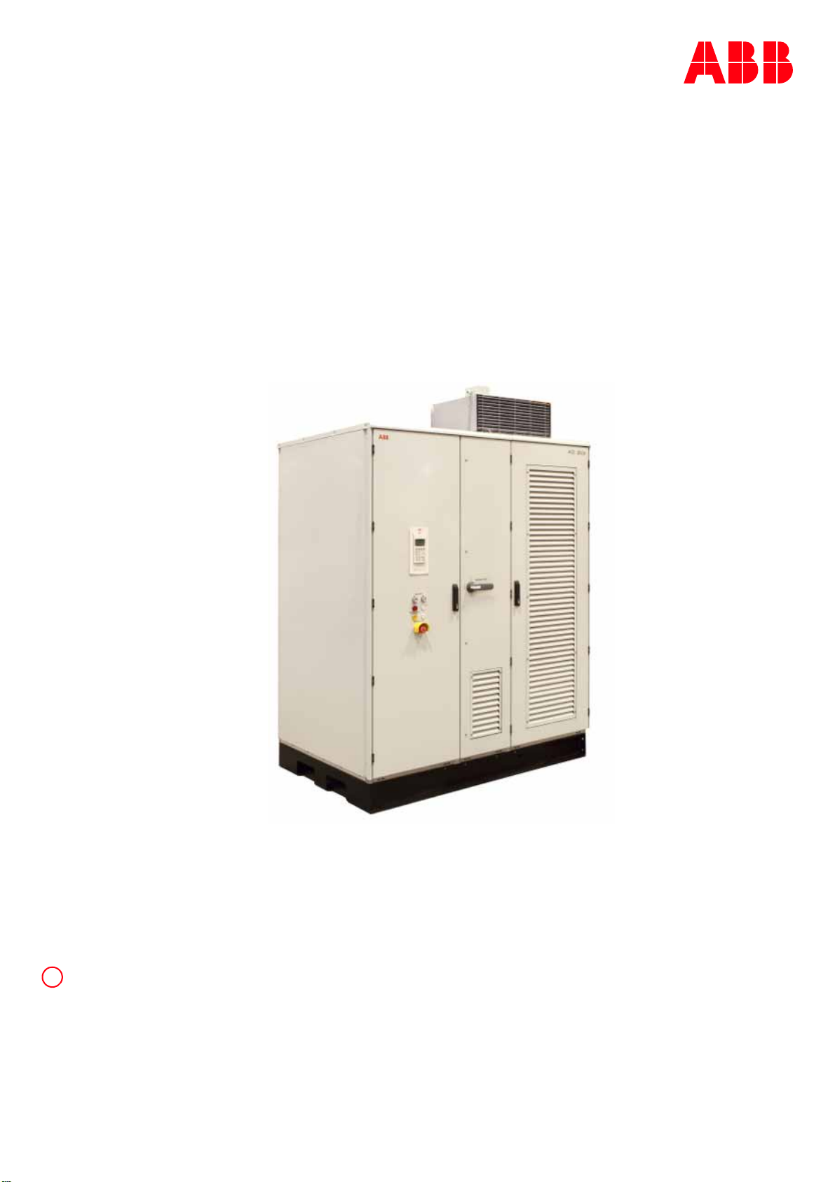
The drive presented in this manual is part of an
industrial environment where voltages are present
that contain a potential hazard of electric shock
and / or burn. For this reason, only personnel who
have a thorough knowledge of the drive and the
industrial environment and have obtained the
required qualification must handle, install, operate,
or maintain the drive.
The manual addresses personnel who are responsi-
ble for unpacking, transportation, installation,
operation and maintenance of the drive. The per-
sonnel must carry out the below listed tasks in a
manner that does not cause physical harm or dan-
ger, and that ensures the safe and reliable func-
tioning of the drive.
—
Commissioning of the drive must
only be performed by qualified
and certified ABB personnel.
Handling
The personnel must be skilled and experienced in
unpacking and transporting heavy equipment.
Mechanical installation
The personnel must be qualified to prepare the
installation site according to the site and equip-
ment requirements and to perform the installation
accordingly.
Electrical installation
The personnel must have a sound knowledge of the
relevant electrical codes and specifications cover-
ing low and medium voltage equipment, be experi-
enced with electrical wiring principles, and know
the electrical symbols typically used in wiring dia-
grams.
Operation
The personnel include all persons who operate the
drive from the local operating panel of the drive.
The personnel must know the functions of the
operating panel, be adequately trained for the
drive, and know the driven process. Special knowl-
edge of frequency converter technology is not
required.
Maintenance
The personnel include all persons who:
• are qualified to carry out preventive and correc-
tive maintenance on drive as described in this
manual,
• are thoroughly familiar with the drive,
• have a sound knowledge of the relevant electri-
cal codes and specifications covering low and
medium voltage equipment,
• are able to assess the hazards associated with
the energy sources of the drive system and act
correspondingly,
• know the safe shutdown and grounding proce-
dures for the drive system.
Responsibilities of the user
It is the responsibility of those in charge of the
drive to ensure that each person involved in the
installation, operation or maintenance of the drive
has received the appropriate training and has thor-
oughly read and clearly understood the instruc-
tions in this manual and the relevant safety
instructions.

10 ACS2000 DFE UM 3BHS360367 ZAB E01 REV. K
—
Intended use of equipment
Those in charge of the drive must ensure that the
drive is only used as specified in the contractual
documents, operated under the conditions stipu-
lated in the technical specifications and on the rat-
ing plate of the drive, and serviced in the intervals
as specified by ABB.
Use of the drive outside the scope of the specifica-
tions is not permitted.
Intended equipment use also implies that only
spare parts recommended and approved by
ABB must be used.
Unauthorized modifications and constructional
changes of the drive are not permitted.
Quality certificates and applicable standards
The following certificates and conformity declara-
tions are available with ABB:
• ISO 9001 / ISO 14001 certificates stating that
ABB Group has implemented and maintains
a management system that fulfills the require-
ments of the normative standards
•ECconformitydeclaration
• List of the standards the drive complies with.

GENERAL INFORMATION ON MANUAL AND EQUIPMENT 11
—
Items covered by delivery
Delivery comprises the following items (see the fig-
ure below):
•Drive(1)
• Transformer (can be integrated or non-inte-
grated) (2)
Fan unit(s) (3),
shipped separately.
• The number of fan units delivered depends on
the cooling configuration ordered.
• Rating label (4)
•Doorkeys(5)
• Phase module replacement kit (6)(if selected as
additional option).
-Note: This kit varies depending on the drive
output type.
•Sealingcompound(7) (only when 6-hole cable
entry is provided).
Identifying the delivery
The drive and accessories are identified by the type
code printed on the rating label. The rating label is
located on the front of the control compartment
door.
The label provides information on the type of drive,
the rated voltage, the frequency and the current of
the main and the auxiliary power supply.
—
0-1
1
2
333
4
5 6 7
!
For information on items supplied, see
the shipping note.

12 ACS2000 DFE UM 3BHS360367 ZAB E01 REV. K

Abbreviations, trademarks, related
documentation

14 ACS2000 DFE UM 3BHS360367 ZAB E01 REV. K
—
Terms
The following table lists terms and abbreviations
you should be familiar with when using the manual.
Some of the terms and abbreviations used in the
manual are unique to ABB and might differ from
the normal usage.
Term / Abbreviation Meaning
AMC circuit board Application Motor Controller
The digital signal processor is the heart of the control system of the drive.
Auxiliary ride-through Ride-through is the ability of the drive to continue the operation in a controlled manner if the
auxiliary power supply is interrupted for a short time.
The auxiliary ride-through function guarantees correct fault indication and proper trip sequencing if
the auxiliary power supply to the drive is lost. The function is activated by a parameter. During ride-
through the power for the control circuits of the drive is supplied by an internal backup system. The
ride-through time is limited by the internal backup system.
DFE Diode Front End
The DFE is the line-side diode rectifier of the drive. The rectifier enables two-quadrant operation of
the drive.
Converter Short form for ACS2000 frequency converter
Cluster A cluster is a synonym for a group of hardware modules of the drive control system.
Crowbar The crowbar is an electrical circuit which is designed to prevent damage from the power electronics
components of the drive if an overvoltage occurs, eg, in the power supply. The overvoltage is
prevented by putting a short-circuit or a low resistance path across the voltage source.
DDCS Distributed Drive Control System
DDCS is an acronym for a serial communication protocol designed for data transfer via optical
fibers.
Drive Short form for ACS2000 frequency converter
Drive system The drive system includes all equipment used to convert electrical into mechanical power to give
motion to the machine.
DriveBus Communication link dedicated for ABB drives
DriveDebug DriveDebug is part of ABB’s DriveWare®software tools for drives using the DDCS communications
protocol. DriveDebug runs on computers with Windows®operating systems. DriveDebug is a
specialist’s tool used to diagnose, tune and troubleshoot ABB drives.
DriveWindow DriveWindow is a DriveWare®product. DriveWindow is a 32 bit Windows®application for
commissioning and maintaining ABB drives equipped with optical communication links.
DriveMonitor DriveMonitor is a monitoring and diagnostics system that allows secure access to the drive via the
internet from a remote location. DriveMonitor provides long-term monitoring functions that allow
to infer the equipment status and improve the equipment performance.
Equipment Frequency converter and related equipment
EMC Electromagnetic compatibility
All measures to suppress electromagnetic disturbances caused by different electrical equipment in
the same electromagnetic environment, and to strengthen the immunity of the equipment to such
disturbances.
FE Functional earth
Ground Earth
To ground The conducting path (eg, conductor) between the electric equipment (eg, frequency converter) and
the earth. The electric equipment is connected to the earth, eg, by a grounding set or a grounding
switch.
INU Inverter Unit
The INU converts the DC voltage to the required AC motor voltage and frequency.
IOEC module Term of ABB’s I/O system. The I/O module is an active input and output device for digital and analog
signals.
Line voltage RMS voltage of the main power supply of the drive
MCB Main Circuit Breaker
The MCB is a major protection device of the drive system and connects / disconnects the main
power supply to the drive. The MCB is controlled entirely by the drive.
PCB Printed Circuit Board
PCC Point of Common Coupling. The PCC is the point in the electrical power supply system where the
responsibility of the utility changes to the industrial customer. The utility is responsible to provide
clean voltage and current with respect to harmonic distortion up to the PCC. The industrial customer
is responsible not to distort voltage and current by its electrical systems.

ABBREVIATIONS, TRADEMARKS, RELATED DOCUMENTATION 15
PE Protective Earth
Phase module The phase module is a compact assembly of wired components including power semiconductors
and circuit boards that serves as a standardized building block for the DFE and the INU of the drive.
PPCS Power Plate Communication System
PPCS is an acronym for a serial communication protocol designed for data transfer via optical fibers
between AMC circuit board and INTerface circuit boards.
RTD Resistance Temperature Detector or Device
The RTD is a temperature sensor where the change in electrical resistance is used to measure the
temperature.
Safeline ABB synonym for uninterruptible power supply
Supervisory signal Indicates the operating condition of a circuit or device.
SW Software
TEU Terminal Unit
Short form for terminal compartment of the drive
Zero speed threshold Used in the manual to indicate that the drive has reached the value “zero speed” that is set in a
parameter. The value can be set in the range of 0 and maximum speed (the unit for the speed is
rpm).
Term / Abbreviation Meaning

16 ACS2000 DFE UM 3BHS360367 ZAB E01 REV. K
—
Trademarks
Names that are believed to be trademarks of other
companies and organizations are designated as
such. The absence or presence of such a designa-
tion should however not be regarded as an offence
of the legal status of any trademark. The following
registrations and trademarks are used in this man-
ual:
Related documentation
The following documents are available for further
information:
Term / Abbreviation Meaning
Windows®Registered trademark of Microsoft Corporation
Industrial ITTM Trademark of ABB
DriveWare®Registered trademark of ABB
Advant®Registered trademark of ABB
Advant FieldbusTM Trademark of ABB
Ethernet®Registered trademark of Xerox Corporation
Profibus®Registered trademark of Profibus International (P.I.)
Modbus®Registered trademark of the Modbus IDA organization
Title Document number
Schematics
Layout drawing Project-specific
Specifications
Main circuit breaker engineering guideline 3BHS104785 ZAB E01
ABB MVD ACS Motor Specification 3BHS824803 ZAB E01
Technical project Specification Motor 3BHS824804 ZAB E01
ABB MVD ACS High Performance Motor Spec 3BHS824805 ZAB E01
ABB MVD ACS High Speed Motor Spec 3BHS824806 ZAB E01
ACS2000 power cable specification 3BHS189994 ZAB E01
Power cables engineering guideline 3BHS542290 ZAB E01
Maintenance
Preventive maintenance schedule ACS2000 4MFB005215 ZP3 E01
Drive monitoring
DriveMonitor user manual 3BHS268039 ZAB E01
Serial communications interfaces
AF 100 fieldbus - NAFA-01 installation and start-up guide 3BFE58919837 ZAB E01
Modbus TCP - NETA-21 remote monitoring tool user’s manual 3AUA0000096881 EXT E01
Modbus RTU - NMBA-01 installation and start-up guide 3AFY58919772 ZAB D01
Profibus - NPBA-12 installation and start-up guide 3BFE64341588 ZAB D01

Important note on main circuit
breaker

18 ACS2000 DFE UM 3BHS360367 ZAB E01 REV. K
The main circuit breaker (MCB) is a major protec-
tion device of the drive. If a serious fault occurs in
the drive, the MCB must disconnect the main
power supply to the drive immediately. The main
power supply must be disconnected without delay
on an open or trip command from the drive to pre-
vent hazard to the personnel and further damage
to the equipment. The MCB is located on the pri-
mary side of the input transformer.
0-1
shows the conceptual single-line diagram of a
typical drive system, including main power supply,
MCB, input transformer, drive and electrical motor.
The MCB is defined as a switching device to dis-
connect the power supply whenever required by
the process or when a fault occurs. Typical devices
used as MCBs are:
• Vacuum circuit breakers
•SF6circuitbreakers
• Fused contactors or motor control centers
The overcurrent protection relay is part of the
switchgear.
—
0-1
M
CT
MCB control interface
Higher-level
control system
Local MCB control
Main power supply
MCB
Protection
relay
Input
transformer
Drive
Motor
—
References
—
0-1 Drive system overview

IMPORTANT NOTE ON MAIN CIRCUIT BREAKER 19
—
Safety and protection requirements
For safety and protection reasons, the MCB must
meet the stipulated minimum requirements of the
specifications of ABB MV Drives. It is the system
integrator's responsibility to ensure that the mini-
mum require-ments are met. The minimum
requirements for the MCB are stated in this note
and in the respective MCB specifications, which are
available for each medium voltage drive from ABB.
The safety requirements for the drive are based on
the following standards:
• ISO 13849-1 Safety of machinery - Safety-
related parts of control systems - Part 1: Gen-
eral principles for design, section 6.2.6 Cate-
gory 3
• IEC 60204-1 Safety of machinery - Electrical
equipment of machines - Part 1: General
requirements
Minimum requirements for MCB and MCB control
• The MCB open and / or trip command has to be
wired directly from the drive to the MCB. It is
not permitted to wire the trip command
through any PLC or DCS system if it is not certi-
fied to meet SIL 3 level requirements, and to ful-
fill the timing requirements outlined below.
Opening of the MCB by the drive must be possi-
ble at any time. It is not permitted to interrupt
the open and / or trip command, for example by
a local-remote switch in the MCB.
• When the MCB is in service position, the drive
must have exclusive control of closing the MCB.
Local closing of the MCB is not permitted.
• The maximum opening time of the MCB must
never exceed the product or project-specific
maximum time defined in the MCB specifica-
tions. Typical maximum values for the drive are
defined as follows:
- Maximum protection trip time: 75 ms
The maximum protection trip time is the
maximum allowed breaking time (open and
arcing) of the breaking device after the open
command has been initiated to prevent fur-
ther damage to the drive, eg, diode failures.
- Maximum safety trip time: 250 ms
The maximum safety trip time is the maxi-
mum allowed time to ensure safe disconnec-
tion of the main power supply to prevent any
hazard to personnel.
In order to meet the stipulated safety require-
ments, it is recommended that:
• the MCB is equipped with two independent
opening coils, or
• the MCB is equipped with one opening coil and
an undervoltage coil for monitoring of the con-
trol voltage, or
• an upstream protection coordination scheme is
provided which uses the "breaker failure" (ANSI
50BF) signal to automatically trip the upstream
breaker, in case the MCB does not open. The
upstream breaker must open within the maxi-
mum safety trip time after a failure has
occurred.
—
0-2
Short-circuit occurs
Open and or trip command is set at the
drive control output
No further damage to drive No hazard to personnel
Max. protection trip time
Max. safety trip time
—
References
—
0-2 MCB opening timing
diagram

20 ACS2000 DFE UM 3BHS360367 ZAB E01 REV. K
Other manuals for ACS2000 DFE
2
Table of contents
Other ABB DC Drive manuals

ABB
ABB NOCH0070-6 Series User manual

ABB
ABB ACS880-07 User manual

ABB
ABB DCS880 series User manual

ABB
ABB ACH480 User manual

ABB
ABB ACS5000 User manual

ABB
ABB ACS880 Series User manual

ABB
ABB ACS580-01 Series Installation manual

ABB
ABB UNITROL 1010 User manual

ABB
ABB ACQ580-01 Series Installation manual

ABB
ABB DCS880 series User manual

ABB
ABB ACS250 Owner's manual

ABB
ABB ACH580-01 Series User manual

ABB
ABB ACH580-01 Series User manual

ABB
ABB ACS 160 User manual

ABB
ABB ACS880 Series Troubleshooting guide

ABB
ABB ACS550-02 User manual

ABB
ABB ACS580MV User manual

ABB
ABB ACH550-01 User manual

ABB
ABB ACQ580-31 Series Installation manual

ABB
ABB ACQ580-07 User manual