ABB Emax Link 2 UR 1558 User guide

—
APPLICATION GUIDE
Emax Link™2 Abbreviated
Low voltage, metal-enclosed,
drawout switchgear

2EMAX LINK 2 ABBREVIATED LV SWITCHGEAR APPLICATION GUIDE

EMAX LINK 2 ABBREVIATED LV SWITCHGEAR APPLICATION GUIDE 3
—
Table of contents
4 General description
5 Product description
6 General information
7 Section weight
Assembly construction
8 Structure description
8 Cubicle/device label
8 Section arrangement
9 Busbar compartments
9 Bus phases
10 Bus ratings and sizes
10 Horizontal neutral bus (optional feature)
10 Ground bar
11 Vertical distribution busbar
11 Device compartment
11 Section and location numbering
11 Device location numbering
12 Wireways
Installation guidelines
13 Installation location requirements
14 Preparation
14 Section installation sequence
14 Install and connect shipping splits
14 Position shipping splits
14 Connect sections
15 Splice horizontal busbars
17 Attach switchgear to floor
17 Attach overhead lifting device
18 Raise lift device
18 Align wheels
18 Push device off the forklift
18 Operating the overhead lifting device
19 Connect cable and wiring
21 Direct connections to main sections
21 Connect between horizontal and vertical wireways
21 Connect control wiring between sections
22 Inspect busbars
22 Exterior metal damage repair
22 Maintenance schedule
23 Semi-annual inspection
23 Annual inspection
23 18-to-36-month inspection
24 Torque fasteners
24 Torque table

4EMAX LINK 2 ABBREVIATED LV SWITCHGEAR APPLICATION GUIDE
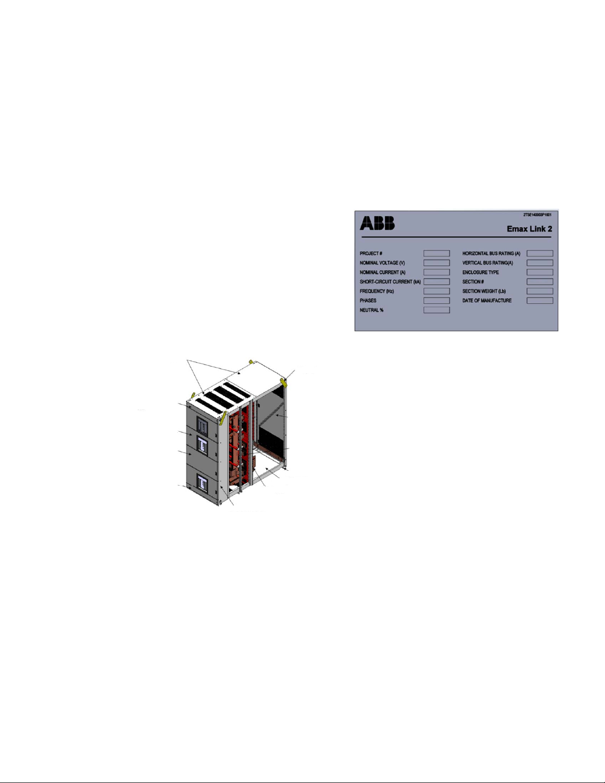
ABB Emax Link 2 Abbreviated Low Voltage
Switchgear is manufactured with rugged 12-gauge
steel and electrodeposition coated gray paint to
stand up to normal industrial environments. The
switchgear is compartmentally designed to enclose
all electrical parts. Emax Link 2 is UL Recognized to
UL 1558 and is designed, manufactured, and tested
in accordance with ANSI/ IEEE C37.20.1 and C37.51.
Front and rear doors/panels and doors are
manufactured in 12-gauge and 14-gauge steel
NEMA Type 1 ratings as standard.
All sections include a top and a bottom horizontal
wireway for control wiring.
Units feature front, hinged doors held closed by
one or more latches.
The rear door is secured by a swing handle with a
door-lock mechanism that secures the door at four
points of contact. A bolted rear cover is optional.
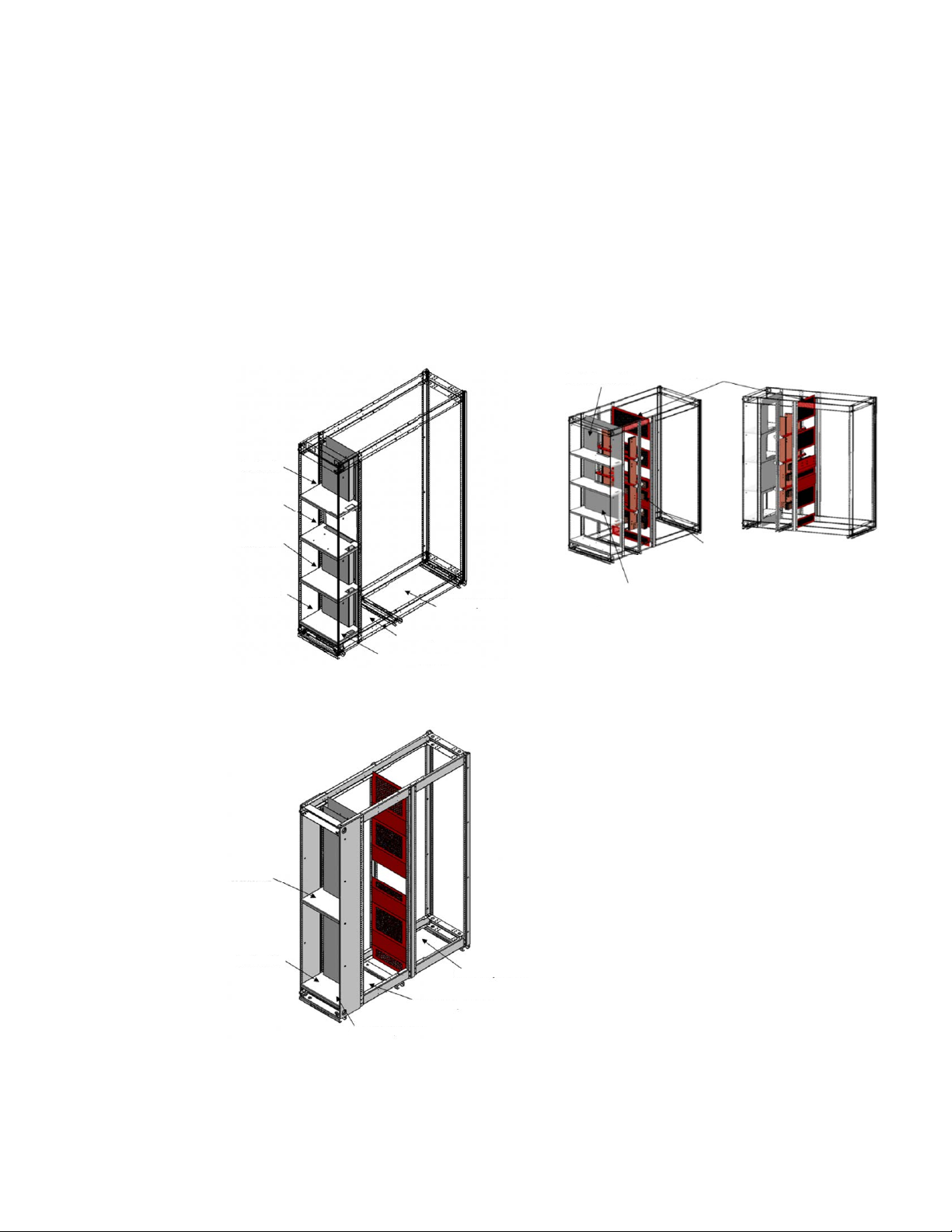
The switchgear assembly consists of one or more
metal-enclosed vertical sections joined side-by-
side with a horizontal bus. Each vertical section is
an enclosed, vertical metal cabinet that contains
devices, wireways and other internal components.
Up to three vertical sections are arranged and
joined side-by-side at the factory. This facilitates
shipping, handling and installation. A lineup may
include more than one shipping split depending on
the configuration.
Each vertical section is divided into several areas:
The instrumentation/device compartment in the
front of the section, the bus compartment in the
middle and the cable compartment for the end
terminal connections at the back.
The front compartment within a section can be
divided into smaller modules to accommodate
devices of different heights. One section may be
divided into as many as four of these modules.
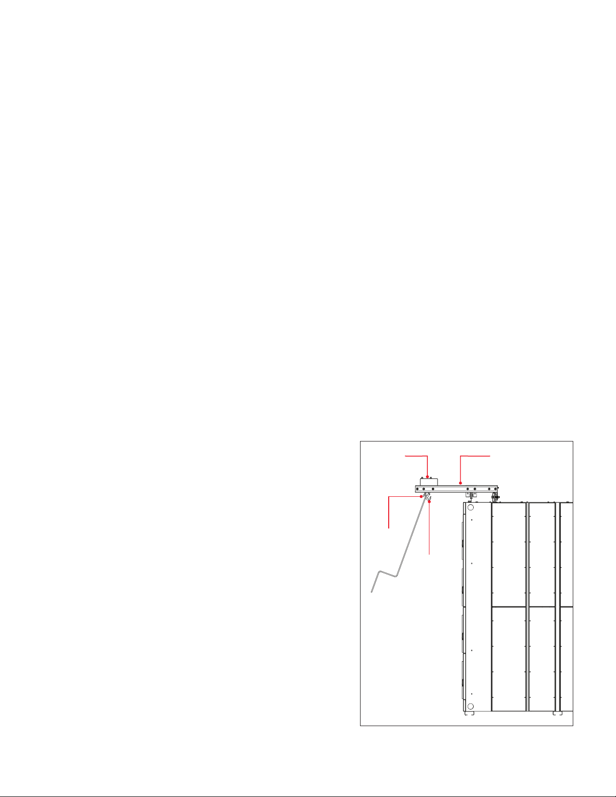
A traveling, overhead lifting device is available to
assist with handling breakers. The front section of
the switchgear provides support for the lifting
device. The device travels the full width of the
switchgear. Utilizing a lifting yoke, the breaker lifts
from a completely withdrawn circuit breaker cradle.
A worm-gear-driven mechanism and wire rope,
operated by a removable hand crank, provide
lifting power.
—
General description
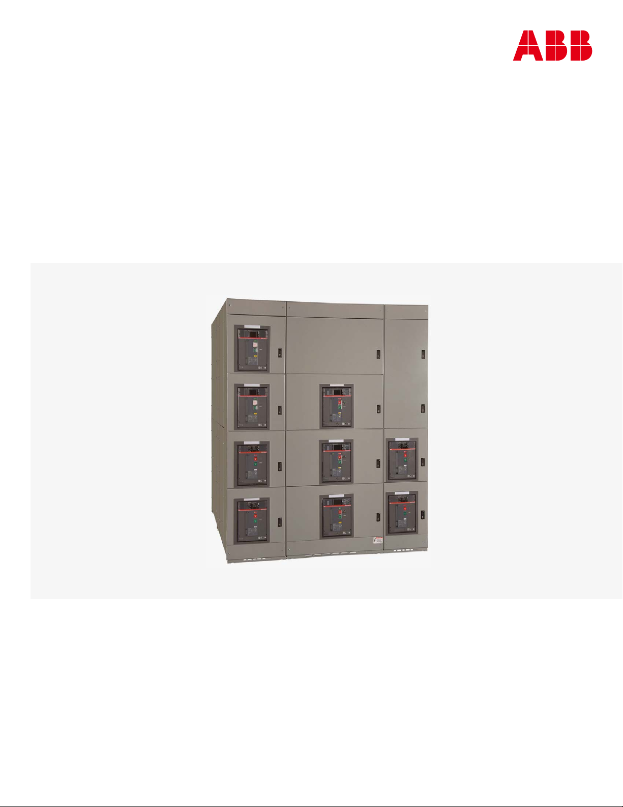
Enter the ever-growing low voltage switchgear market without the high overhead
costs of labor, design and testing. The ABB Emax Link 2 UR 1558 structures provide a
turnkey solution for OEMs. Emax Link 2 combined with SACE®Emax 2 circuit breakers
provides advanced power distribution technology and helps enhance safety in a fast,
flexible and cost-effective solution for the OEM low voltage switchgear market.
Lifting
hook
Winch
hook
Carriage
assembly
Winch
mechanism

EMAX LINK 2 ABBREVIATED LV SWITCHGEAR APPLICATION GUIDE 5
—
Product description
Ratings
Switchgear ratings
Maximum rated voltage
Rated operating voltage
Rated frequency
Rated current
Neutral current-carrying capacity
Circuit breaker ratings
Rated current
Interrupting ratings @ rated voltage
Rated short-time current
Rated current
Interrupting ratings @ rated voltage
Rated short-time current
Rated current
Interrupting ratings @ rated voltage
Rated short-time current
Rated current
Interrupting ratings @ rated voltage
Rated short-time current
Environmental conditions
Enclosure rating
Ambient temperature (storage) °°C)
Ambient temperature (operation) °°C)
Humidity
Altitude
ANSI switchgear altitude correction factors (C37.20.1)
Altitude Voltage Current
Notes: Intermediate values may be obtained by interpolation.
For devices used in switchgear assemblies, standards covering the specific devices should be used to determine the specific altitude correction factors.

6EMAX LINK 2 ABBREVIATED LV SWITCHGEAR APPLICATION GUIDE
—
Product description
General information
ABB Emax Link 2 assemblies are shipped in one or
more shipping splits, depending on the total
number of vertical sections, or the limitations of
handling facilities at the installation site. A typical
configuration includes three vertical sections.
Shipping splits are mounted on wooden skids and
enclosed in a covering to protect them from
atmospheric conditions during shipment, however
the covering is not suitable for storage outdoors.
For instructions regarding the various components,
refer to the manual associated with each product.
Crate dimensions (H x W x D)
Number of sections in shipping block
By selection width
Section depth
72" 84"
Width
Length

7
EMAX LINK 2 ABBREVIATED LV SWITCHGEAR APPLICATION GUIDE 7
—
Product description
Section weight
Weights listed in the following table are approximate. Consult equipment shipping documents for actual
weights and dimensions.
Section estimated weight
Section depth
Typical configuration Section width 72.0 in (1829 mm) 84.0 in (2134 mm)
Auxiliary section
Main/Tie section
Main-Tie-Main section
Feeder section
Breaker/cradle
E1.2 E2.2 E4.2 E6.2
Accessories
Overhead lifting device

8EMAX LINK 2 ABBREVIATED LV SWITCHGEAR APPLICATION GUIDE
Structure description
The switchgear may accept power cable entry from
the top, bottom or both. Bus duct or closed-couple
connections are also an option.
The base channel is a feature utilized to install the
switchgear in its final location. It will raise a unit by
1.67 inches and is an alternate method to welding
the base channel to a metal structure.
All openings in the enclosure feature IP20
protection to help prevent vermin, rodents and
snakes from entering the switchgear from the top,
bottom and sides of the equipment.
Lifting angles are provided to allow lifting by crane.
Cubicle/device label
Each cubicle and device are prominently labeled to
display approval agency marking.
Section arrangement
Vertical sections are composed of the following
three main compartments:
1. Device compartment: Composed of up to four
vertical locations that house the installed
devices, which are the main functional elements
of the switchgear.
—
Assembly construction
Top plates
Lifting angles
Base channel
Bottom plate
Cable lugpad
Compartment barrier
Rear door or rear
covers/cable
compartment
Main horizontal
bus system
Top horizontal
wireway door
Breaker
compartment
Instrument/auxiliary/
empty compartment
Bottom horizontal
wireway door

EMAX LINK 2 ABBREVIATED LV SWITCHGEAR APPLICATION GUIDE 9
—
Assembly construction
2. Busbar compartment: The compartment where
main and distribution busbar systems are
installed.
3. Cable compartment: Location where power
connections are made to the rear of the device.
Emax Link 2 standard compartments
Busbar compartments
The main horizontal busbar is installed in the
busbar compartment located at the middle of the
section. The main horizontal bus may be supplied in
various configurations depending on the current
rating.
Horizontal busbars
Bus phases
The horizontal busbar is located at the bottom of
each section. The phase arrangement of 3-phase
horizontal busbar and vertical busbars is A, B, C
from top to bottom, or left to right, as viewed from
the front.
The busbar systems are installed in the lower level
busbar compartment. The tie busing will be
installed at the upper level.
Location 1
Location 2
Location 3
Location 4
Cable compartment
Bus compartment
Device compartment
Location AB
Location CD
Cable compartment
Bus bar compartment
Device compartment
Segregation wall to
device compartment
Main Busbar
Breaker segregation
Segregation wall to
cable compartment

10 EMAX LINK 2 ABBREVIATED LV SWITCHGEAR APPLICATION GUIDE
Bus ratings and sizes
The number of installed bars per phase depends on
the current ratings. Up to five bars per phase may
be installed.
Busbar systems are 3-phase, 3-wire or 3-phase,
4-wire. See Horizontal Neutral Bus for details.
There is the option of only having 3-phase, 4-wire
in the incoming section and the rest of the lineup
will be 3-phase, 3-wire.
Sections in the same shipping split will be
connected at the factory. For lineups that combine
multiple shipping splits, each shipping split must
be connected together during installation using
the splice kits provided on each split. The splice
kits’ bolts must be tightened to the specified
torque. See the Torque Table provided in this
manual.
Horizontal bus is available in silver-plated copper or
optional tin-plated copper.
Bus ratings and sizes
Horizontal neutral bus (optional feature)
busbar is provided in the busbar compartment
above the lower A-phase horizontal busbar. For
4-wire systems that have no line-to-neutral load
requirements, an incoming neutral connection
point can be provided to facilitate the power
system grounding connection, but without neutral
horizontal or distribution busbars.
Ground bar
A continuous, sectionalized, copper ground bus,
cable compartment, the ground bar is linked to the
ground bar in other sections by a splice link.
Ground bars
The switchgear ground bus must be grounded
using equipment- grounding conductors sized
according to NEC standards, or by bonding the
ground bus to the raceway enclosing the main
supply conductors according to NEC standards.
—
Assembly construction
3,200A set
MBB 2,000
1,600A set
MBB 2,000
4,000A set
MBB 2,000
2,000A set
MBB 2,000
5,000A set
MBB 2,000
Ground bar

EMAX LINK 2 ABBREVIATED LV SWITCHGEAR APPLICATION GUIDE 11
Vertical distribution busbar
There are three standard vertical busbar types: full,
three-quarters and half distribution busbars. All
are located inside the busbar compartment. These
busbars are arranged in A-B-C order from left to
right.
Vertical Bottom/Full Distribution Busbar
Device compartment
Each device compartment is divided vertically into
four locations, A through D. Locations A, B, C or D
may contain feeders, equipped space, control or
blank. Location B or C may contain main, tie,
feeders or equipped space feeders. Location D may
contain main, feeder or equipped space feeders.
Standard breaker unit instruments installed on the
doors are pilot lights, push buttons, control
switches and maintenance switches.
In addition to the standard items listed above,
instrument compartments may also include
ammeters, voltmeters, high-resistance grounds
(HRGs), potential transformers and relays. These
instruments can be installed inside the
compartments or on the front of the instrument
compartment door.
Section and location numbering
Each section is sequentially numbered as the
general arrangement drawings are prepared. The
left-most section is usually section 1, the next
section to the right is 2, etc. This numbering
scheme ensures the correct sequencing of vertical
sections during installation.
The combination of the numeric section code (1, 2,
3, etc.) with the vertical level designation (A, B, C,
and D) uniquely describes each device’s location in
the switchgear. For example, the device mounted in
the top of the first section of a lineup would be
coded 1-A.
Device location numbering
(A and B locations can be combined; C and D
locations can be combined)
—
Assembly construction

12 EMAX LINK 2 ABBREVIATED LV SWITCHGEAR APPLICATION GUIDE
Wireways
Cable compartment
A cable compartment is provided in each section.
The compartment is located on the back of the
section, extending the full height of the structure.
It is used to route top or bottom incoming
conductors to the individual devices within the
section. The overall depth of a standard cable
compartment for 72-inch section depth is 33.68 in
(856 mm), and for 84-inch section depth is 45.68 in
(1160 mm).
The overall depth of the switchgear is 72 in (1829
mm) or 84 in (2134 mm) having two cable
compartment depths.
Cable compartments may be equipped with two
12 gauge [0.1 in (2.5 mm) thick] steel covers or
single/double full-height, hinged doors. The doors
swing open 120° for easy accessibility.
Cable compartment may have an optional cable
support structure which is adjustable in vertical
and horizontal position.
Top horizontal wireway
The Top wireway provides the space for
interconnection wiring and is covered by a steel,
hinged door secured by a bolted cover.
Top horizontal wireway
Bottom horizontal wireway
The bottom horizontal wireway is covered by a
steel, bolted cover and wireway includes a cutout
for control conduit entry.
Bottom horizontal wireway
Control conduit entry cutout
Vertical wireway
The vertical wireway is formed by the segregation
walls on either side of the device and is directly
connected to the top and bottom with the
horizontal wireways.
Vertical wireway
—
Assembly construction
Height (In) Width (In)

EMAX LINK 2 ABBREVIATED LV SWITCHGEAR APPLICATION GUIDE 13
1. Before beginning the installation, ensure that
you have all necessary components:
• Switchgear sections
• Fastener hardware to connect sections
• Shipping split connection hardware
2. Check that all components are in good condition.
If there is any evidence of damage to the
equipment, contact an ABB representative to
evaluate the condition of the equipment before
proceeding with installation.
3. Carefully review all supplied project drawings
and notes to familiarize yourself with the layout
and construction of the switchgear.
4. Based on the footprint shown on the general
arrangement drawings, mark the floor for all
drill holes necessary to fasten the switchgear
or base frame to the floor, and for cable conduits
(if applicable). See Fastening Sections to a
Base Frame.
5. Install power and secondary (control) conduits
before moving the switchgear to the site. The
available space for conduits appears on the floor
plans supplied with the switchgear. Conduits
should not extend more than 1.0 in (24 mm)
above floor level.
Installation location requirements
The installation must meet the following
requirements:
• Indoor location protected from moisture and
dramatic temperature changes. For longest
equipment life, install the switchgear in an
enclosed room with temperature and humidity
control and filtered, and forced air ventilation.
• Level the site, preferably including a base frame
that is either embedded in the concrete floor or
rests on a false floor on supports. The floor must
be straight and level to +/- ¼ in (6 mm) over the
entire length of the line-up.
• Prepare proper openings in the floor, wall and
ceiling for cables, conductors, pipes, bars and
ventilation in accordance with the construction
drawings provided.
• Allow at least 2.5 ft (750 mm) from the top of the
highest section to the ceiling, and at least 3.0 ft
(920 mm) between the left and right end sections
and the walls.
• Allow at least 3.5 ft (1066 mm) between the unit
and the rear wall.
—
Installation guidelines
Clearances – front view
Clearances – side view
• For sections with left-mounted doors, provide at
least 3.0 ft (920 mm) between the left wall and the
left-end section so the doors can be opened more
than 120°.
• Ambient temperature is to be above -22 °F (-30 °C)
condensing humidity. If ambient temperatures
below 23 °F (-5 °C) will be experienced while in
service, the manufacturer should consider addition
of space heating or other means to help enable
proper circuit breaker operation.
• Allow sufficient space for future expansions,
if required
• Supporting brackets, beams, enclosures and
foundation frames should be painted or treated
with a corrosion-resistant coating. To facilitate
installation and maintenance, the site should
also have:
- Convenient alignment with other equipment.
- Accessibility for maintenance.
- Adequate lighting.
- Free access to the electrical equipment rooms.
Keep Area Free
3 ft Min.
(915 mm)
3.5 ft Min.
(1066 mm)
10 ft Min.
(3048 mm) 12 ft Min.
(3048 mm)
FrontRear
3.5 ft Min.
(1066 mm)
3 ft Min.
(915 mm)
Keep Area Free

14 EMAX LINK 2 ABBREVIATED LV SWITCHGEAR APPLICATION GUIDE
Preparation
Follow all instructions related to the installation
of the switchgear to help avoid potentially
hazardous situations that could result in serious
injury or death.
If the switchgear will be installed near operational
equipment, it may be appropriate to erect
temporary barriers between that equipment and
the switchgear.
If you are adding sections to existing switchgear,
turn off all power supplying the equipment before
working on or inside it, and follow appropriate
lockout/tagout procedures.
Always use an appropriate voltage-sensing device
to confirm that the power is off prior to installing
or working with the switchgear.
Section installation sequence
Sections can be installed or added in any order,
and new sections may be added between existing
sections. If the sequential order designated during
manufacturing is altered on site by adding sections
to an existing lineup, the horizontal bus must be
reviewed as the length depends on the width of
the sections to be installed together. The main
bussing must match, and the related drawings
must be updated.
When adding, removing or rearranging sections, do
not exceed the maximum amperage available on
the horizontal bussing.
Install and connect shipping splits
Note: Diagrams showing the location of fasteners
and the appropriate torque values are included in
the Torque Table section of this manual.
—
Installation guidelines
Position shipping splits
Remove the shipping splits from their pallets or
skids. If you need to support a multiple-section
shipping split at the base after removing it from
the pallet, use supports at the corner of each
section. A two-section split must be supported at
8 points rather than 4.
Position the shipping splits in their final
arrangement and location. Connecting the sections
together before attaching them to the floor and/or
wall will help simplify splicing the horizontal bus.
If doors won’t close easily or panels are twisted or
stressed, this may indicate that the site is not
leveled. You may be able to shim the sections to
level them.
Connect sections
Note: Use only the provided fasteners to assemble
the switchgear.
Begin the installation at either the left or the right
end of the lineup by connecting the frames of the
sections together. The left side of each frame is
fitted with threaded inserts. Sections are fitted on
the right side with the necessary rivet nuts. Insert
the bolts from the left side of one frame to the
inserts in the adjoining section to the right.
Frame connection using spacer bolts
Front view
1/2-13 Hex nut
1/2-13, grade 5
Hex head bolt

EMAX LINK 2 ABBREVIATED LV SWITCHGEAR APPLICATION GUIDE 15
Section frame connections
Connect the sections using the provided hardware,
The hardware bag is typically affixed to the front of
the switchgear shipping split.
After connecting the sections, you can attach the
lineup to the floor (see below).
Splice horizontal busbars
Note: The fasteners provided with the switchgear
include an integrated thread coating that helps
ensure they will remain at the torque value.
The bus in each section is designed to allow
splicing with the bus of the adjacent sections to
create a continuous horizontal bus. The splice links
are located on the right-hand side for the neutral
and phase A, and on the left-hand side for phases B
and C of each section. Slide the splice links to the
right or left to connect the bus to the adjacent
section.
1. After installing and connecting the shipping
splits, connect the main horizontal bus splice
links and tighten the hardware to the specified
torque. Splice kits supplied from the factory are
installed on the right-hand side for neutral and
phase A, and on the left-hand for phases B and C
of each shipping split.
—
Installation guidelines
2. Loosen the bolts holding the splice link(s) in
place and slide the link(s) to straddle the
horizontal bus in the adjacent (right/left-hand)
section. Carefully position each splice link so that
it straddles the bus equally on both the left- and
right-hand sections.
The maximum gap between the left and right
busbar should be 0.9 in +/- 0.1 in (25 mm +/- 3 mm).
Busbar gap
1/2-13 Hex nut
1/2-13, grade 5
Hex head bolt
(0.984 in ± 0.118)
25 mm ± 3

16 EMAX LINK 2 ABBREVIATED LV SWITCHGEAR APPLICATION GUIDE
Slide link to adjacent busbar
3. Tighten the four M12 bolts. For easiest
installation, use a long ratchet extension that
extends outside the front of the wireway and an
18 mm socket with a universal joint. Torque to 52
ft-lbs (70 Nm). Use only the fasteners provided
for busbar connections. Do not use additional
locking fluid.
4. Once torqued to the proper value, draw a line
across each fastener head and the surrounding
metal surface so you can visually check whether
the fastener has been properly torqued.
Torque marks
—
Installation guidelines
Repeat this process for all splice kits, including the
neutral bus if provided. You must splice the
horizontal ground bus between adjacent sections
in the cable compartment. Splice links are provided
on the right-hand side of each section for neutral
and Phase A, and on the left-hand side for Phases B,
C and the ground. The links may be loosened and
bridged to the adjacent section.
Note: The holes at the ends of all busbars ensure
adequate adjustment within the required
tolerances. If the lineup has been installed properly,
the busbars in adjacent sections will line up. Never
drill or modify busbars if alignment is poor. Ensure
that the adjacent sections are properly and
completely connected together mechanically
before connecting the horizontal bus splices.
Do not clean the contact surfaces on new
switchgear.
Refer to the Torque Table for all tightening torques
for horizontal bus bolted connections.
Main horizontal Busbar splice kit

EMAX LINK 2 ABBREVIATED LV SWITCHGEAR APPLICATION GUIDE 17
Carriage stop
—
Installation guidelines
Attach switchgear to floor
After completing the internal connections, attach
the switchgear to its location. Switchgear may be:
• Attached to a base frame that has been secured
to the floor (preferred method).
• Bolted directly to a concrete floor by setting
vertical mounting bolts in the floor.
• Bolted to floor channels.
Floor mounting anchor plan
Attach the sections using four bolts through the
holes in the section base to the floor or base frame.
ft-lbs (61 Nm).
Attach overhead lifting device
The driving mechanism allows for easy raising and
lowering of circuit breakers into the compartments.
See the corresponding ABB drawing for detailed
operating instructions.
To attach the lifting device:
1. Remove the carriage stop from one end of
the lineup.
Remove carriage stop
2. Loosen all rails for the overhead lift device
and mount the locator plates. Note that the
plates have round bosses that mate with holes
in the rails.
3. Adjust the rails as required to loosely secure
the locator plates in place with the bosses in
their mating holes.
NOITCES B-B
ELAC
S6
:1
LIATED A
ELAC
S6
:1
057.2
58.96
B
B
526.2
86.66
832.2
58.65
734.1
94.63
621.91
08.584
834.1
25.63
0
526.2
86.66
450.43
69.468
057.96
56.1771
A
2.750
[69.85]
Detail A
Scale 1:6
Section B-B
Scale 1:6
B
B
NOITCES B-B
ELACS6:1
LIATED A
ELACS6:1
057.2
58.96
B
B
526.2
86.66
832.2
58.65
734.1
94.63
621.91
08.584
834.1
25.63
0
526.2
86.66
450.43
69.468
057.96
56.1771
A
69.750
[1771.65]
2.238
[56.85]
2.625
[66.68]
1.437
[36.49]
1.438
[36.52]
19.126
[485.80]
34.054
[864.96]
0
2.625
[66.68]

18 EMAX LINK 2 ABBREVIATED LV SWITCHGEAR APPLICATION GUIDE
4. After mating all locator plates in place with the
rails, secure the locator plates and the rails.
5. Position overhead lift device on the tines of
forklift. Raise the overhead lift device up to the
rails on the frame.
Raise lift device
Align wheels on the front rail and behind the rear
rail. Adjust the upper-rear wheel to minimize
vertical movement.
Align wheels
—
Installation guidelines
Push device off the forklift
Push the overhead lift device off the forklift onto
the rails.
Test the continuous movement of the overhead lift
device. If the movement is correct, reinstall the
carriage stop bracket.
Operating the overhead lifting device
Observe the following requirements when
operating the circuit breaker lifting device:
• The wheels must be properly set on track.
• Do not depend upon the drum attachment to
support the full breaker weight.
• Allow 4-5 wraps of wire rope to remain on
the drum.
• Prevent snarling, kinking or knotting the
wire rope.
• Lift only circuit breakers.
• Do not alter the lifting device or the circuit
breaker lifting yoke.
• Never walk or stand under a suspended breaker.
• Do not leave a circuit breaker suspended.

EMAX LINK 2 ABBREVIATED LV SWITCHGEAR APPLICATION GUIDE 19
—
Installation guidelines
Connect cable and wiring
—
E1.2 breaker connection table
Section
width (inches)
Continuous
current Run backs sizes
Number of
lamination
Number of lug
pad/phase
Number of holes
per phase
NA
NA
—
E2.2 breaker connection table (1600A and 2000A)
Section
width (inches)
Continuous
current Run backs sizes
Number of
lamination
Number of lug
pad/phase
Number of holes
per phase
NA
NA
—
E4.2 breaker connection table (1600A & 3200A)
Section
width (inches)
Continuous
current Run backs sizes
Number of
lamination
Number of lug
pad/phase
Number of holes
per phase
NA
NA
—
E6.2 breaker connection table (4000A & 5000A)
Section
width (inches)
Continuous
current Run backs sizes
Number of
lamination
Number of lug
pad/phase
Number of holes
per phase

20 EMAX LINK 2 ABBREVIATED LV SWITCHGEAR APPLICATION GUIDE
—
Installation guidelines
A
B
F
E
38.29 D
C
G
A
B
2.24
4.24
2.04
3.79
Ă0.98
2.70
7.45
3.85
1.25
2.05
3.79
Ă0.98
Detail A
Scale 1 : 5
Detail B
Scale 1 : 5
Space for
Co
ntrol cable
Space for
Power cable/conduit
Bottom/top entry
Section depth Conduit space depth
Distance to bus
compartment
Distance between
base channels
A B C D
Section width Conduit space width Distance between anchor holes
E F G
Table of contents
Other ABB Industrial Equipment manuals
Popular Industrial Equipment manuals by other brands

GSi
GSi TopDry installation manual

Brugg Pipesystems
Brugg Pipesystems CASAFLEX UNO instruction manual

Nordmann Engineering
Nordmann Engineering MultiPipe Installation and operating instructions

Gentec
Gentec Beamage M2 user manual

SUHNER MACHINING
SUHNER MACHINING BEA 16 Technical document

GESTRA
GESTRA QuickCC Original Installation Instructions

Vestil
Vestil D Series instruction manual

Numa
Numa Champion 330 Care & maintenance instructions

erowa
erowa PowerChuck P without base plate manual

CommScope
CommScope HELIAX FiderFeed DFJ-4S112B Technical publication

Parkside
Parkside MAGNETIC TORCH STAND PBHM 16 A1 Operation and safety notes

metex
metex PRO MILL E3 Operator's manual