5.
Commissioning
6.
Characteristics and technical data Commissioning
PVI-AEC-GPRS-Quick Installation Guide EN-RevA
EFFECTIVE 2014-05-16
© Copyright 2014 ABB. All Rights Reserved.
Specications subject to change without notice.
Commissioning
PVI-GSM/GPRS
Wireless Communication
Method of Data transmission GSM-GPRS-SMS
Circuit Switch Data (CSD) transceiver bit rate 9600 bps
GPRS Class 10
Frequency Band EGSM 850/900/1800/1900 MHz
Output power Class 4 (2W) @850/900 MHz or Class 1 (1W) @1800/1900 MHz
SIM 3V Micro-SIM card
Antenna Parameter
Frequency range 824-890 MHz / 1850-1990 MHZ
Gain <3 dBi
Impedance 50 Ohm
Input power >2W Peak power
VSWR <= 2:1
Polarization N/A
Connector SMA Male
Protection Degree Indoor use
Environmental parameters
Ambient Temperature Interval -20/+ 55°C (-4/131°F)
Degree of Environmental Protection IP20
Relative Humidity 25…95% @40 °C
Mechanics
Dimension (H x W x D) 58mm x 90mm x 36mm / 2.3" x 3.5" x 1.4" (2 module DIN 43880)
Weight 0.1 kg / 0.22 lb
Safety
Certication CE
Note. Features not specically mentioned in this data sheet are not included in the product
- Checking Modem Status And Activity
Using the PVI-AEC-EVO display and buttons (see PVI-AEC-EVO Quick Installation Guide), access the “INFORMATION” → “GSM / GPRS” menu. This menu con-
tains three sub-menus which can be navigated using the arrow keys. The three sub-menus are: MODEM STATUS, MODEM SIGNAL and MODEM ACTIVITY.
Modem Status
The sub-menu “Modem Status” indicates whether the modem is ready to transmit data using the GPRS service.
Status Description
READY GPRS-En The modem is ready to transmit data (The prompt GPRS-En appears when, in the internal connection conguration
web page, the “Gprs” connection type is selected for data transfer to the portal)
NOT READY GPRS-En The modem is not ready to transmit data (Verify the conguration of the APN eld in the menu Cong→Network)
Modem Signal
The sub-menu “Modem Signal” provides an indication of the GSM/GPRS signal strength. The signal strength is represented on a numerical scale from 0 to 31.
Please refer to the following table:
Value Meaning
0 – 12 Weak signal: possible lack of connection
13 – 19 Unstable connection: possible temporary loss of connection
20 – 31 Stable connection
The value of the Modem Quality represents the quality of the signal of data communication, sent directly by the provider of the phone service. Whereas GPRS
management system of the provider does not implement this function the expansion module will report a signal quality factor equal to 99.
Modem Activity
The sub-menu “Modem Activity” shows the current activity of the PVI-GSM/GPRS modem.
Status Description
MODEM_CHECK_REG Verifying registration status of the SIM Card with the mobile phone network provider
MODEM_PRESENCE Verifying whether the modem is present
MODEM_INIT_GSM Registering with the mobile phone operator’s network
MODEM_INIT_GPRS Initialising GPRS service
MODEM_GPRS_ON Activating GPRS service
MODEM_GPRS_OFF Suspending GPRS service
MODEM_GPRS_CONNECTION Active GPRS connection
MODEM_WAIT_CALL Checking for GSM incoming data call
MODEM_ANSWER_CALL Responding to GSM incoming data call
MODEM_ANSWER_MSG Connection to remote modem is active
MODEM_CHECK_SMS Checking for incoming SMS
MODEM_SENT_SMS The modem is sending an SMS
MODEM_READ_SMS Reading incoming SMS
MODEM_DELETE_SMS Deleting an SMS received
MODEM_SOCKET_WRITE Sending data to portal
- Checking The GPRS Modem Operation
Once connected to the PVI-GSM/GPRS module, the PVI-AEC-EVO unit can interact with the user via SMS. In particular, the system is capable of receiving SMS
and, on the basis of the text contained in the message, sends information via SMS or initiates data transmission to the portal. These features can be used to test
the correct functioning of the unit.
As the system cyclically turns among the states of GPRS connection for the sending of data to the portal and the reporting of SMS, during the sending of data to
the portal will not be possible to manage the SMS messages.
Sending SMS Messages
The system is capable of responding to SMS messages sent from an ordinary mobile phone. The messages that the system recognises, and which it is therefore
able to respond to, are the following:
Function Sms Text Description/Response
System structure request 000000#system test#
The system responds by the indication of the total number of inverters present in the
system and the number of centralised inverters and string inverters.
Example of response SMS:
Datalogger S/N: 000202# Command:SYSTEM TEST#
Total Modules:2# Central Modules:0#
Grid Modules:2# 11/6/23,10:31:22
Power and energy level request 000000#read energy#
The system responds by the indication of the instantaneous power produced by the
system, and the energy produced daily and weekly by the whole plant.
Example of response SMS:
Datalogger S/N: 000202#Command:READ ENERGY#Ouput Power:0.2 KW#Daily Ener-
gy:4.9 KWh#Weekly Energy:47.6 KWh#11/6/21,18:33:13
The SMS messages above can be used to verify that the system has sent the SMS. It is recommended to send a test SMS message in order to ensure that SMS
messages can actually be sent.
Sending data to the portal
Once the system has been commissioned and correctly congured, it will send data to the portal management server according to the conguration settings en-
tered on “Cong” → “Network” page of the integrated web server. It is also possible to initiate a data transmission to the portal or checking the data connectivity
to the portal via the SMS messages described in the following table:
Function Sms Text Description/Response
Send data to portal management
server 000000#upgrading data# The system sends instantaneous data to the portal management server. One received the
request the datalogger will send an SMS to notify a TEST IN PROGRESS.
Connecti test to the portal 000000#test ip portal#
The system check the correct connectivity between the portal and the datalogger. One
received the request the datalogger will send an SMS to notify a TEST IN PROGRESS.
Example of response:
Datalogger S/N: 000202#Command:TEST IP PORTAL#SUCCESS# 11/6/21,18:38:16
- List of available sms messages
The system sends SMS messages on the basis of client requests, depending on alarm conditions detected in the system.
The SMS messages the system sends upon the client’s request are described in the table “Sending SMS Messages” paragraph.
The SMS alerts generated by alarm conditions are listed in the following table.
The system is only capable of sending SMS alerts if a telephone number for an addressee has been set up. Refer to paragraph “Conguration of data
transmission” for conguration instructions.
Type of alarm Code Description
System alarm
I005 Wake Up The message is sent when the system starts up.
W004 AC Failure The message is sent when the 24Vdc power supply fails (message available only if back-up
module PVI-BATTERY-PACK is present which keeps the system active) (*)
E006 Event on Din1 The message is sent when a change in the status of digital input on Din1 is detected (*)
E007 Event on Din2 The message is sent when a change in the status of digital input on Din2 is detected (*)
E008 Event on Din3 The message is sent when a change in the status of digital input on Din3 is detected (*)
E009 Event on Din4 The message is sent when a change in the status of digital input on Din4 is detected (*)
E010 Event on Din5 The message is sent when a change in the status of digital input on Din5 is detected (*)
E011 Event on Din6 The message is sent when a change in the status of digital input on Din6 is detected (*)
Inverter alarm
E501 Comm Fault The message is sent when the data logger does not receive information from any inverter (*)
E502 No prod The message is sent when the system detects that one of the inverters has not increased its
energy production for more than one hour (*)
Stringcomb Alarm E001 Burnt Fuse The message is sent when it is detected a blown fuse in a Stringcomb (*)
(*) Once normal function has been restored, a second SMS message is sent to report the end of the alarm condition.
- Checks prior to commissioning
Before beginning the commissioning procedure, please check the following:
- Check that the SIM card is properly inserted in the specic slot
- Check that the antenna cable is correctly connected to the PVI-GSM/GPRS module
- Check that the PVI-GSM/GPRS modem is correctly connected to the PVI-AEC-EVO
- Commissioning procedure
For details regarding the PVI-AEC-EVO system connection to the power supply, please refer to the PVI-AEC-EVO Quick Installation Guide
- Connect the PVI-AEC-EVO to the mains voltage by the specic protection switch. Verify that the PVI-AEC-EVO has started-up correctly and is properly po-
wered (LEDs should ash during start-up). At the end of the start-up phase, both the “Power ON” LEDs (GREEN) of both the PVI-AEC-EVO and the PVI-GSM/
GPRS should remain steadily light up.
If there is no SIM card or it has not been inserted correctly, the POWER ON LED will ash on and off repeatedly, 15 seconds on / 15 seconds off.
- After a few seconds the “TX/RX” LED will ash; in this phase the system will be registered to the mobile phone service provider’s network.
If the TX/RX LED does not ash, verify that the SIM card has been activated, and that the place where the module is installed is in range of GSM/
GPRS services.
- Verify that the PVI-AEC-EVO has the correct version of FW AVR. To carry out this check use the PVI-AEC-EVO buttons, and verify the display messages:
a. Press the ENTER key
b. Insert the password “0000” and press ENTER
c. Select the menu “INFORMATION” and press ENTER
d. Select the menu “PRODUCT” and press ENTER
e. Scroll through the menu items until you reach “FIRMWARE AVR”. If the FW version is less than 0.0.124, update the FW following the directions contai-
ned in the PVI-AEC-EVO Quick Installation Guide.
- Conguration of data transmission
The conguration of the PVI-AEC-EVO system for data transmission through the PVI-GSM/GPRS expansion module must be carried out via the pages of the
system’s integrated web server. The procedure for accessing the local web pages is described in the PVI-AEC-EVO Quick Installation Guide.
- Access the web server page “Cong” → “Network”
- Set up the elds for the GPRS module:
Parameter Description
APN Access Point Name: name of the access point for the GPRS network(*)
Username User name for connection to the APN (*)
Password Password for connection to the APN (*)
Tel SMS Mobile phone number to which SMS notications will be sent (**)
(*) Obtain the correct APN from your mobile phone network provider; check whether a Username/Password is necessary for connection. If so, get a
valid account for connection to the APN.
(**) Please use the international dialling code prex “00”; and not “+”. For example, for Italy: 0039 → OK; +39 → NOT OK.
- Set up the elds for data transmission:
Parameter Description Value
IP Address Portal Portal management server IP address 151.22.100.235
Port Data transmission port 80
Method Method of data transmission to the portal Standard ABB
Type sending Connection type for data transfer to the portal GPRS
Eth Sample Data Rate (5 minutes min) Sampling period if connecting to the portal via Ethernet N/A
Eth Send Data (10 minutes min) Time needed for sending data to the portal if connecting via Ethernet N/A
Gprs Sample Data Rate (5 minutes min) Sampling time if connecting to the portal via GPRS Congurable (Default = 5 min)
Gprs Send Data (5 minutes min) Time needed for sending data to the portal if connecting via GPRS Congurable (Default = 5 min)
Assembly Instructions
Contact us
www.abb.com/solarinverters
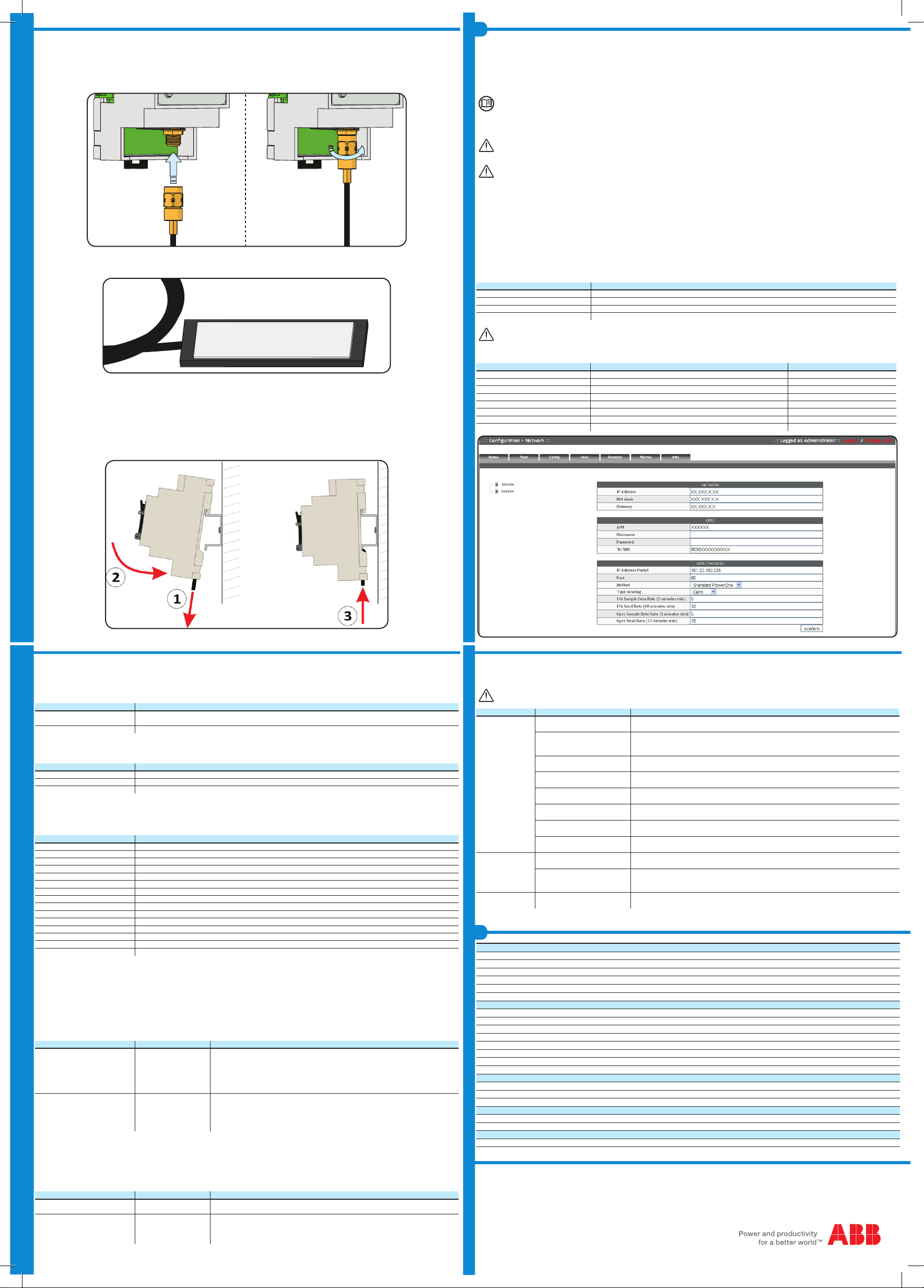
3. Connecting the antenna
To enable the PVI-GSM/GPRS modem to send out the data collected from the PVI-AEC-EVO, it is necessary to connect the supplied antenna to the PVI-GSM/
GPRS connector. When choosing where to position the antenna, take the following points into consideration:
- Install the antenna in a sheltered place, protecting it from weather.
- Install the antenna within range of the GSM/GPRS signal
- Do not install the antenna in metal casing or close to other antennas/transmitters.
PVI-GSM/GPRS
VIN AC: 15-30 V
VIN DC: 18-48 V
Ta(°C): -20 to +55
TX/RX
Power ON
PVI-GSM/GPRS
VIN AC: 15-30 V
VIN DC: 18-48 V
Ta(°C): -20 to +55
TX/RX
Power ON
- It’s recommended to carefully clean the surface where the antenna will be positioned and held in place by its adhesive strip (on reverse side).
4. Mounting on din rail
The unit, comprising the now connected PVI-AEC-EVO and PVI-GSM/GPRS modem, must be mounted on the DIN rail (UNI EN 50022) using the special catch
on the back of each of the two devices.
To correctly mount the unit on the DIN rail, follow the procedure below:
- Using a at head screwdriver, pull out the tabs in order to release the catch.
- Place the combined PVI-AEC-EVO and PVI-GSM/GPRS modem unit on the DIN rail.
- Push the tab in order to lock the catches.


