manuals.online logo
Brands
  1. Home
  2. •
  3. Brands
  4. •
  5. ABB
  6. •
  7. Inverter
  8. •
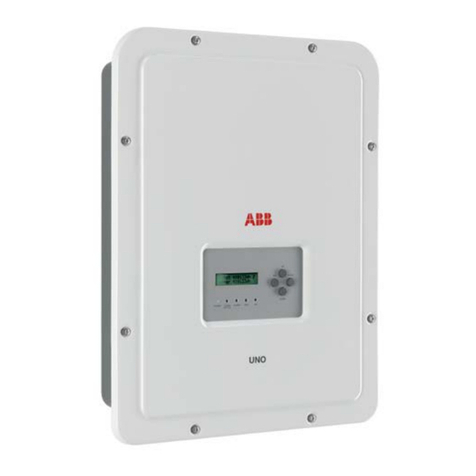
  9. ABB UNO-2.0-TL-OUTD User manual

ABB UNO-2.0-TL-OUTD User manual

In addition to the notes below, please read and follow the safety and installation information
provided in the installation manual. The technical documentation and the interface and
management software for the product are available on the website.
This equipment must be used following the guidelines provided in the manual.
Failure to do so may impair the inverter safety features.
Quick installation guide
UNO-2.0/3.0/3.6/4.2-TL-OUTD
(from 2.0 to 4.2 kW)
ABB solar inverters
1.
Labels and Symbols
Inverter Models and Components
2.
Lifting and transport
3.
EN
Assembly Instructions
6.
List of components supplied
5.
Choice of installation location
4.
7.
Input connection (DC)
The labels on the inverter carry the branding, the main technical data and the identication of the equipment and the manufacturer
A4 1:1 1/1 AA
A.Statuti
A.Butini
29/05/2015
G.Fiesoli
Pantone
Process Cyan C Process Yellow C
LABEL MATERIAL: 3M type 7331 (UL R/C, PGJI2)
INKS: Refer to UL File MH16411
LABEL CONTENT: Fixed as shown in the picture
SIZE: 63 mm (height) x 90 mm (width)
29/05/2015
29/05/2015
29/05/2015 C.Granci
All material
used and finished product, must meet the requirements of the curr ent RoHS rec ti
ive 2002/95/EC .
Title
Issued
Modified
D
D
esign approved
Elec. Eng. approved
Mfg. appr oved
Size Scale Dim. in mm Sheet Drawing No. Revision
© Copyright 2014 Power-One Italy Spa. All rights reserved. Reproduction, use or disclosure to third parties without express written authority is strictly forbidden.
Regulatory Label of UNO-2.0-TL-OUTD
UNO LOW COST (V1N)
XLP.V1N02.0AL
MODEL:
UNO-2.0-TL-OUTD
IP65
5 minutes
-25 to + 60 °C
-13 to +140 °F
INVERTERSOLAR
www.abb.com/solar
600 V
80 - 580 V
12.5 A
180 - 500 V
16 A
230 V 1Ø
50 Hz
1800 W @ 45 °C amb.
2000 W @ 45 °C amb.
10 A
2000 VA
V
dc max
I
dc max
V
dc MPP
V
dc, Full Power
I
sc max
V
acr
f
r
I
ac max
P
acr (cos = ±0.9)
φ
P
acr (cos = 1)
φ
S
max
Made in Italy
DIN V VDE V 0126-1-1
PROTECTIVE CLASS: I
A4 1:1 1/1 AA
A.Statuti
A.Butini
29/05/2015
G.Fiesoli
Pantone
Process Cyan C Process Yellow C
LABEL MATERIAL: 3M type 7331 (UL R/C, PGJI2)
INKS: Refer to UL File MH16411
LABEL CONTENT: Fixed as shown in the picture
SIZE: 63 mm (height) x 90 mm (width)
29/05/2015
29/05/2015
29/05/2015 C.Granci
All material
used and finished product, must meet the requirements of the curr ent RoHS rec ti
ive 2002/95/EC .
Title
Issued
Modified
D
D
esign approved
Elec. Eng. approved
Mfg. appr oved
Size Scale Dim. in mm Sheet Drawing No. Revision
© Copyright 2014 Power-One Italy Spa. All rights reserved. Reproduction, use or disclosure to third parties without express written authority is strictly forbidden.
Regulatory Label of UNO-3.0-TL-OUTD
UNO LOW COST (V1N)
XLP.V1N04.0AL
MODEL:
UNO-3.0-TL-OUTD
IP65
5 minutes
-25 to + 60 °C
-13 to +140 °F
INVERTERSOLAR
www.abb.com/solar
600 V
80 - 580 V
16 A
200 - 500 V
20 A
230 V 1Ø
50 Hz
2700 W @ 45 °C amb.
3000 W @ 45 °C amb.
15 A
3000 VA
V
dc max
I
dc max
V
dc MPP
V
dc, Full Power
I
sc max
V
acr
f
r
I
ac max
P
acr (cos = ±0.9)
φ
P
acr (cos = 1)
φ
S
max
Made in Italy
DIN V VDE V 0126-1-1
PROTECTIVE CLASS: I
A4 1:1 1/1 AA
A.Statuti
A.Butini
29/05/2015
G.Fiesoli
Pantone
Process Cyan C Process Yellow C
LABEL MATERIAL: 3M type 7331 (UL R/C, PGJI2)
INKS: Refer to UL File MH16411
LABEL CONTENT: Fixed as shown in the picture
SIZE: 63 mm (height) x 90 mm (width)
29/05/2015
29/05/2015
29/05/2015 C.Granci
All material
used and finished product, must meet the requirements of the curr ent RoHS rec ti
ive 2002/95/EC .
Title
Issued
Modified
D
D
esign approved
Elec. Eng. approved
Mfg. appr oved
Size Scale Dim. in mm Sheet Drawing No. Revision
© Copyright 2014 Power-One Italy Spa. All rights reserved. Reproduction, use or disclosure to third parties without express written authority is strictly forbidden.
Regulatory Label of UNO-3.6-TL-OUTD
UNO LOW COST (V1N)
XLP.V1N06.0AL
MODEL:
UNO-3.6-TL-OUTD
IP65
5 minutes
-25 to + 60 °C
-13 to +140 °F
INVERTERSOLAR
www.abb.com/solar
850 V
350 - 820 V
11 A
380 - 700 V
15 A
230 V 1Ø
50 Hz
3240 W @ 45 °C amb.
3600 W @ 45 °C amb.
16 A
3600 VA
V
dc max
I
dc max
V
dc MPP
V
dc, Full Power
I
sc max
V
acr
f
r
I
ac max
P
acr (cos = ±0.9)
φ
P
acr (cos = 1)
φ
S
max
Made in Italy
DIN V VDE V 0126-1-1
PROTECTIVE CLASS: I
A4 1:1 1/1 AA
A.Statuti
A.Butini
29/05/2015
G.Fiesoli
Pantone
Process Cyan C Process Yellow C
LABEL MATERIAL: 3M type 7331 (UL R/C, PGJI2)
INKS: Refer to UL File MH16411
LABEL CONTENT: Fixed as shown in the picture
SIZE: 63 mm (height) x 90 mm (width)
29/05/2015
29/05/2015
29/05/2015 C.Granci
All material
used and finished product, must meet the requirements of the curr ent RoHS rec ti
ive 2002/95/EC .
Title
Issued
Modified
D
D
esign approved
Elec. Eng. approved
Mfg. appr oved
Size Scale Dim. in mm Sheet Drawing No. Revision
© Copyright 2014 Power-One Italy Spa. All rights reserved. Reproduction, use or disclosure to third parties without express written authority is strictly forbidden.
Regulatory Label of UNO-4.2-TL-OUTD
UNO LOW COST (V1N)
XLP.V1N08.0AL
MODEL:
UNO-4.2-TL-OUTD
IP65
5 minutes
-25 to + 60 °C
-13 to +140 °F
INVERTERSOLAR
www.abb.com/solar
850 V
350 - 820 V
12.5 A
380 - 700 V
15 A
230 V 1Ø
50 Hz
3780 W @ 45 °C amb.
4200 W @ 45 °C amb.
20 A
4200 VA
V
dc max
I
dc max
V
dc MPP
V
dc, Full Power
I
sc max
V
acr
f
r
I
ac max
P
acr (cos = ±0.9)
φ
P
acr (cos = 1)
φ
S
max
Made in Italy
DIN V VDE V 0126-1-1
PROTECTIVE CLASS: I
The labels on the equipment must absolutely NOT be removed, damaged, dirtied, hidden, etc.
If the service password is requested, the eld to be used is the serial number -SN: YYWWSSSSSS
In the manual and/or in some cases on the equipment, the danger or hazard zones are indicated with signs, labels, symbols or icons.
Obligation to consult
manual
General warning - Important
safety information Hazardous voltage Hot surfaces
IP65
Protection rating of
equipment
Temperature range
Without insulation tran-
sformer
Direct and alternating
currents, respectively
Positive pole and negative
pole of the input voltage
(DC)
Obligation to use safety
clothing and/or personal
protection
equipment
Point of connection for
grounding protection.
Stored energy discharge
time
10
01
Inverter model
02
Inverter Part Number
03
Inverter Serial Number
04
Week/Year of manufacture
UNO-X.X-TL-OUTD-Y
P/N:PPPPPPPPPPP
WO:XXXXXXX
SO:SXXXXXXXX Q1
SN:YYWWSSSSSS WK:WWYY
01
02
04
03
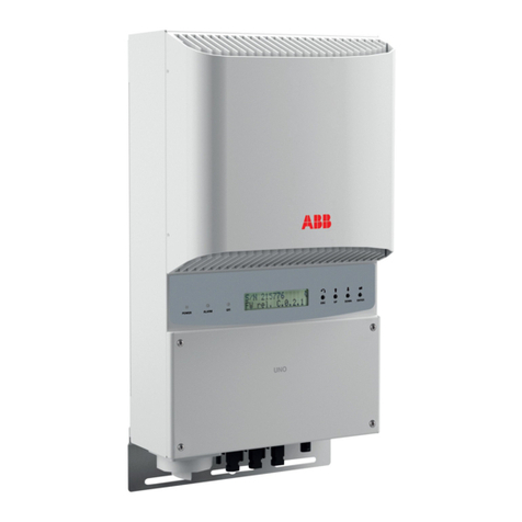
The inverter models to which this installation guide refers are available in four power ratings: 2.0 kW, 3.0 kW, 3.6 kW and 4.2 kW.
Two types are available for each model: standard or with DC disconnect switch (Version -S).
Main components
01
Bracket
02
Locking screws
03
Heat sink
04
Anti-condensation valve
05
Front cover
06
LED panel
07
Display
08
Keyboard
09
DC input connectors
10
AC output connector
12
SD Card slot
14
RS485 connector
16
DC disconnect switch
18
Stand-alone board (optional)
19
External ground connection
20
Service cable glands
Available components Quantity
Bracket for wall mounting 1
Plug, screw and washer for wall
mounting 2 + 2 + 2
M5x10 screw and M5 washer to lock
bracket 2 + 2
M5x10 screw and M5 contact washer
for external ground connection 1 + 2
Two-hole gasket for M20 signal cable
gland and TGM58 cover 1 + 1
Available components Quantity
Securely sealed connection to
connect AC cable 1
Securely sealed connection to con-
nect RS485 serial line cable 1
TORX TX25 L-key
1
Inadditiontowhatisexplainedin this guide, the safetyand installationinformationprovided in theinstallationmanual mustbe read andfollowed.
Thetechnicaldocumentationandtheinterfaceandmanagementsoftware for theproduct are availableat the website.
XXXXXXXXXXXXXXXXXXX
XXXXXXXXXXXXXXXXXXX
ABBsolarinverters
Technical documentation 1
Transportation and handling
Transport of the equipment, especially by road, must be carried out using suitable ways and means in order
to protect the components from violent shocks, humidity, vibration, etc.
Lifting
The means used for lifting must be suitable to bear the weight of the equipment.
Unpacking and checking
The components of the packaging must be removed and disposed of in accordance with the regulations in
force in the country of installation.
When you open the package, check that the equipment is undamaged and make sure all the components
are present.
If any defects or damages are detected, please stop operating, contact the carrier and also promptly inform
the ABB Service Department.
Weight of the modules of the equipment
Model Weight
UNO-2.0/3.0-TL-OUTD
UNO-2.0/3.0-TL-OUTD-S
UNO-3.6/4.2-TL-OUTD
UNO-3.6/4.2-TL-OUTD-S
12 Kg
Environmental checks
- Consult the technical data to check the environmental conditions to be observed
- Installation of the unit in a location exposed to direct sunlight must be avoided (otherwise the warranty
will be cancelled) as it may cause:
1. power limitation phenomena in the inverter (with a resulting decreased energy production by the
system)
2. premature wear of the electrical/electromechanical components
3. premature wear of the mechanical components (gaskets) and of the user interface (display)
- Do not install in small closed rooms where air cannot circulate freely
- Always ensure that the ow of air around the inverter is not blocked so as to prevent overheating.
- Do not install in places where gases or ammable substances may be present
- Do not install in rooms where people live or where the prolonged presence of people or animals is ex-
pected, because of the noise level that the inverter produces during operation. The level of the sound
emission is heavily inuenced by where the inverter is installed (for example: the type of surface
around the inverter, the general properties of the room, etc.) and the quality of the electricity supply.
Installations above 2000 metres
On account of the rarefaction of the air (at high altitudes), particular conditions may occur:
- Less efcient cooling and therefore a greater likelihood of the device going into derating because of
high internal temperatures
- Reduction in the dielectric resistance of the air that, in the presence of high operating voltages (DC
input), can cause arcing (electrical discharges) that may reach the point of damaging the inverter
All installations at altitudes of over 2000 metres must be assessed case by case with the ABB
Service department.
Installation site
- Install on a wall or strong structure capable of bearing the weight of the equipment
- Install in safe, easy to reach places.
- If possible, install at eye-level so that the display can be seen easily
- Install at a height that takes account of the weight of the equipment
- Install vertically with a maximum inclination of 5° (forward or backward)
- Choose a place that enables sufcient space to be left around the unit to enable
easy installation and removal of the object from the assembly surface; respect the
minimum distances indicated
- In the case of multiple installation position the inverters alongside each other;
if the space available does not allow this arrangement, position the inverters in
a staggered arrangement as shown in the gure so that heat dissipation is not
affected by other inverters
Final installation of the inverter must not compromise access to any discon-
nection devices that may be located externally.
Please refer to the warranty terms and conditions available on the website
and evaluate any possible exclusions due to improper installation.
15
cm
20
cm
10cm 10cm
Wall mounting
During installation do not place the inverter with the front cover
05
facing towards the ground.
- Position the bracket
01
so that it is perfectly level on the wall and use it as a template for
drilling.
- Make the 2 holes necessary, using a drill with a 10 mm. diameter bit. The depth of the holes
must be around 70 mm.
- Secure the bracket to the wall with the two 10 mm wall plugs supplied with it.
- Attach the inverter by inserting the two tabs on the bracket
01
into the 2 slots on the inverter
(gures A1 and A2).
- Secure the inverter to the bracket by screwing the lock screws
02
on both sides of the
inverter (gure A3).
- If necessary unscrew the 8 screws and open the front cover
05
to make all accessory
connections.
Do not open the inverter in the case of rain, snow or a high level of humidity
(>95%)
• Once the connections have been made proceed to closing the cover by tightening the 8
screws on the front, adhering to the tightening sequence and torque (2.5Nm).
POWER ALARM GFI
UP
ESC ENTER
DOWN
UNO-2.0/3.0/3.6/4.2-TL-OUTD UNO-2.0/3.0/3.6/4.2-TL-OUTD-S
03
09 04 03 14 20 19 10 09 04 03 1416 20 19 10
01
01
02
03
18
14
10
20
06
07
05
08
12
16
09
04
A
A1A2A3
Check for correct polarity in the input strings and absence of any leakage to ground in the PV generator.
When exposed to sunlight, the PV panels supply DC direct voltage to the inverter.
The inside of the inverter may only be accessed after the equipment has been disconnected from the grid and from the photovoltaic
generator.
Warning! The inverters referred to in this document are TRANSFORMERLESS. This typology implies the use of insulated photovoltaic
panels (IEC61730 Class A Rating) and the need to keep the photovoltaic generator oating with respect to the ground: no terminal of the
generator must be grounded.
The inverter has a single input channel (MPPT) and is equipped with a pair of quick t connectors
09
to
connect the PV generator
If the input strings should be connectd in parallel, they must have the same installation conditions
(number of panels in series, type of panels, orientation and inclination).
Comply with the maximum input current relating to the quick t connectors.
- Refer to the document “String inverter – Product Manual appendix” available at www.abb.com/solarinver-
ters to know the brand and the model of the quick t connector. Depending on the model of the connector
of the own inverter, it is necessary to use the same model and the respective counterpart (check the
compliant counterpart on the website of the manufacturer or in ABB).
Using corresponding parts that are not compliant with the quick t connector models on the
inverter could cause serious damage to the unit and lead to invalidation of the warranty.
- Connect the DC input and always check the tightness of the connectors
09
10.
Connection of the communication and control signals
12.
Commissioning
11.
Instruments
UNO-2.0_3.0_3.6_4.2-TL-OUTD-Quick Installation Guide EN-RevA
EFFECTIVE 2015-07-22
© Copyright 2015 ABB. All Rights Reserved.
Specications subject to change without notice.
8.
Line cable and protection devices
9.
Output connection (AC)
13.
Structure of the display menu
14.
Characteristics and Technical Data
Contact us
www.abb.com/solarinverters
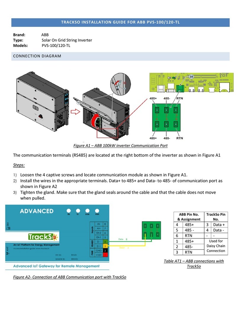
Connection of the communication signals (RS485 line)
On the inverter there is a RS485 communication line for connecting the inverter to monitoring devices. The line may also be used to store settings with the
dedicated advanced conguration software.
The connection of the serial communication cable must be made to the specic RS485 con-
nector
14
present on the lower side of the inverter. An RJ45 connector must be installed on the
cable and the connector in its turn must be placed in the specic corresponding part (provided)
which allows the inverter to maintain its level of IP protection.
1. Install the blocking ring nut on the connector body
2. Install the gasket inside the connector body
3. Feed the cable through the holding ring nut and the connector body
4. Install the RJ45 connector on the cable and push it inside the connector body until it ts into
place.
5. Insert the gasket through the RJ45 connector and position it seated on the connector body
6. Extract the cable from the corresponding part just enough to enable connection with the
connector on the inverter.
At the end of the cable preparation stage, it is possible to proceed with connecting the commu-
nication line to the inverter.
1a. Install the cable on the RS485 connector on the inverter.
1b. Slide the corresponding part on to the cable until it is snug with the RS485
connector of the inverter. The insertion of the corresponding part is guided by
reference points which enable its correct positioning.
2a. Turn the xing ring nut until the two connectors are blocked and check the
correctness of the installation.
2b. Turn the holding ring nut to a tightening torque of 0.6÷0.8Nm
Connection of the control signals
The connection of the control signals must be done on the specic signal terminal block
13
inside the
inverter using a at screwdriver as shown in the gure:
Each cable which must be connected to a signal terminal block
13
must pass through one of the three
service cable glands
20
. Each cable gland (M20) can take a cable with diameter from 7 mm to 13 mm.
A gasket with two holes to insert into the cable gland which enables two separate cables of a maximum
diameter of 5 mm to be accommodated is available.
Warning! To ensure environmental protection rating IP65 it is necessary to tighten the cable gland with a torque of 2.5Nm
Use of the congurable relay
The inverter has a relay, the activation of which is congurable; it is possible to connect external
devices which, depending on the mode selected on the dedicated menu (Inverter > Settings > Alarms
> Set alarm type) can, for example, signal malfunctions. The operating modes that can be set are:
Production, Alarm, Alarm Congurable, Crepuscular, Alarm Congurable Latch, Alarm Congurable
ext, GoGo relay (Auto), GoGo relay (Slave).
The ALARM contact can only be used with systems which guarantee at least additional safety insulation (additional insulation in relation
to the input DC voltage)
Use of the remote ON/OFF signal
The connection and disconnection of the inverter to and from the grid can be controlled through an
external control. If the remote control function is operating, besides being dictated by the presence of
the normal parameters that allow the inverter to connect to the grid, start-up of the inverter also depen-
ds on the state of the terminal R+ compared to the terminal R- present on the connector
13
. When the
R+ signal is brought to the same potential as the R- signal (that is to say when a short-circuit is created
between the two connector terminals) the inverter is disconnected from the grid.
For further information regarding the conguration and use of the communication and control signals terminal block, please see the
manual
The inverter commissioning procedure is as follows:
- Close the DC disconnect switch to supply the inverter with the photovoltaic generator voltage. If the inverter is equipped with a DC disconnect switch (-S
models), turn the DC disconnect switch
16
to the ON position.
- When the inverter is connected to the power supply, the display will show a guided conguration procedure. Press ENTER to set the following:
Inverter date and time
Grid standard and corresponding display language
Warning! The settings become xed after 24 hours of operation of the inverter (the inverter simply has to be powered by PV generator).
- After you have set the grid standard, the message "Initializing...Please Wait” is displayed. Regardless of the input voltage value, the inverter displays various
messages and changes the behaviour of the three LEDs
06
:
INPUT VOLTAGE DISPLAYED MESSAGE LED STATUS DESCRIPTION
Vin < Vstart Waiting sun
Green = FLASHING
Yellow = OFF
Red = OFF
The input voltage is not sufcient to enable connection to the grid.
Vin > Vstart Vac Absent
Green = FLASHING
Yellow = ON
Red = OFF
The input voltage is sufcient to enable connection to the grid: the
inverter waits for the grid voltage to be present to make the parallel
connection.
The inverter is powered SOLELY by the voltage generated by the photovoltaic generator: the current in the attachment to the grid voltage is NOT
SUFFICIENT to switch on the inverter on its own.
- With the inverter in the "Missing Grid" status, close the AC switch downstream of the inverter thus applying the grid voltage to the inverter: the inverter checks
the grid voltage, measures the insulation resistance of the photovoltaic array with respect to ground and performs other auto-diagnostic tests. During the
preliminary checks on the parallel connection with the grid, the green LED keeps ashing, the others are off.
During the check on the grid voltage and the measurement of the insulation resistance, the voltage, grid frequency and insulation resistance values
measured by the inverter are displayed. The inverter ONLY creates a parallel connection with the grid if the grid and insulation resistance parameters
fall within the ranges foreseen by current regulations.
- If the outcome of the preliminary checks on the grid parallel is positive, the inverter connects to the grid and starts to export power to the grid. The green LED
remains constantly lit while the others are off.
LEDs and BUTTONS, in various combinations, can be used to view the status or carry out complex actions that are described more fully in the manual.
LEDs
POWER
GREEN Lit if the inverter is
working correctly. Flashes when
checking the grid or if there is
insufcient sunlight.
LEDs
ALARM
YELLOW The inverter has
detected an anomaly. The ano-
maly is shown on the display.
LEDs
GFI
RED Ground fault on the DC
side of the PV generator. The
error is shown on the display.
The ABB inverters are equipped with a graphic display
07
, consisting of 2 lines of 16 characters each, which can be used to:
- View the operating status of the inverter and the statistical data
- View service messages for the operator
- View alarm and fault messages
- Change the inverter settings
During the normal operation of the inverter the display cycles through the GENERAL INFORMATION. This information relates to the input and output parame-
ters and the inverter identication parameters. By pressing ENTER it is possible to block scrolling on a screen so that it is constantly displayed.
Press ESC to access the main menu which is structured as follows:
> Settings
> Measures
> Set time
> Set cash
> Set RA485 com
> Country Select
> New password
Inverter
> Statistics
> Settings
> Vstart
> Input UV delay
> Service
> Info
> Part No.
> Serial No.
> Firmware
> Remote ON/OFF
> MPPT scan
> Power Limit
> Reactive Power
> Autotest
> Alarms
> Lifetime
> Partial
> Today
> Last 7 days
> Last 30 days
> Last 365 days
> User Period
Display
> Settings
> Info
> Part No.
> Serial No.
> Backlight
> Contrast
> Language
*
Inverter OK
Mon 01 Jan 12:00
E-day XXX Wh
$-day X.XX EUR
E-tot X kWh
E-par X kWh
Pout XXX W
Psetpoint XXX %
Cos-phi fixed
Cosp X.XXX
Pin XXX W
Vin XXX V
Iin X.X A
Igrid X.X A
Fgrid XX.XX Hz
Vgrid XXX V
Ppk XXX W
Ppkday XXX W
Riso XX.X M©
Ileak X.XXXX A
Vbulk XXX V
Vbulk_m XXX V
System
*
Refer to the manual for details regarding use and functions available in the menu.
Warning! Before performing any of the operations described below, ensure the AC line downstream from the inverter has been correctly
disconnected.
For the connection of the inverter to the grid you need 3 connections: ground, neutral and phase. In any case, connection of the inverter to ground is mandatory.
The connection of the grid cable to the inverter is realized through the dedicated AC output connector.
10
by undertaking the following operations:
1. Remove the head of the connector by pressing on the two holding clips
and subsequently loosen the cable gland.
2
1
1a 1b
2. Feed the cable through the connector and cut the cable to correct length
Ensure that the cable's radius of curvature is more than 4 times the diameter
of the cable
3. Prepare the cable respecting the following measurements.
N
L
Max 6 mm²
x:
8 mm
Ø10÷14mm
x
y
y:
30mm
L,N 25 mm
4. Install the single wires (phase, neutral and ground) on the head of the
connector respecting the indications printed on each of the three connection
terminals (tightening torque 0.8...1Nm)
5. Close the connector and tighten the cable gland respecting the torque
(4+1Nm) in order to guarantee the IP65 protection level
1
2
6. Remove the pre-installed protective cover from the inverter.
Insert the corresponding part in the AC output connector
10
being careful
to align the reference points (present on both connectors) which prevent
connection errors.
21 3
In order to maintain the inverter's level of IP protection, the corresponding part must be obligatorily installed with the connected AC cable
or the protective cover, on the AC output connector.
In addition, the connector must not be subject to tensile forces (examples: do not connect weights to the AC cable, do not leave excess
cable windings hanging, etc).
UNO-2.0-TL-OUTD(-S) UNO-3.0-TL-OUTD(-S) UNO-3.6-TL-OUTD(-S) UNO-4.2-TL-OUTD(-S)
Input
Absolute maximum input voltage (Vmax,abs) 600 V 850 V
Input start-up voltage (Vstart) 100...300 V (default 150 V) 300...600 V (default 380 V)
Operating DC input voltage range (Vdcmin...Vdcmax) 0.7xVstart...580 V (min 80V) 350...820 V
Rated DC input voltage (Vdcr) 400 V 500 V 600 V
Input DC nominal power (Pdcr) 2200 W 3200 W 3900 W 4500 W
Number of Independent MPPT 1
DC Voltage MPPT interval (VMPPT min ... VMPPT max) a Pacr 180...500 V 200...500 V 380...700 V
Maximum DC input current (Idc max)12.5 A 16.0 A 11.0 A 12.5 A
Maximum return current (AC side vs. DC side) < 5 mA 4.7 A
Maximum short circuit current (Isc max)15.0 A 20.0 A 15.0 A 15.0 A
Number of DC connection pairs in input 1
DC connection type Quick t PV connector (1)
Type of photovoltaic panels that can be connected at input according to IEC 61730
Class A
Input protection
Reverse Polarity Protection Yes, from current limited source
Input overvoltage protection - Varistors Yes
Insulation check Complying with the local standard
Characteristics of DC disconnect switch (version with DC disconnect switch) 600 V, 25A 1000 V, 16A
Output
AC grid connection type Single phase
Nominal AC output power (Pacr@cosφ=1) 2000 W 3000 W 3600 W 4200 W
Maximum AC output power (Pac max@cosφ=1) 2000 W 3000 W 3600 W 4200 W
Maximum apparent power (Smax) 2000 VA 3000 VA 3600 VA 4200 VA
Nominal AC output voltage (Vacr) 230 V
Output AC voltage range (Vacmin...Vacmax) 180...264 Vac (2)
Maximum AC output current (Iac max)10.0 A 15.0 A 16.0 A 20.0 A
Maximum fault current 18.3 A rms (20ms) 22.9 A rms (20ms)
Contribution to short-circuit current 12.0 A 17.0A 18.0A 22.0A
Inrush current Negligible
Nominal output frequency (fr) 50 Hz / 60 Hz
Output frequency range (fmin...fmax) 47...53 / 57...63 Hz (3)
Nominal power factor and adjustability interval > 0.995, adj. ±0.8 with max Smax
Total current harmonic distortion <3%
AC connections type Female connector from panel
Output Protection
Anti-islanding protection Complying with the local regulations
Maximum AC overcurrent protection 16.0 A 20.0 A 20.0 A 25.0 A
Output overvoltage protection - Varistor 2 (L - N / L - PE)
Operating Performance
Maximum efciency (η
max
) 97.3% 98.4%
Weighted efciency (EURO/CEC) 96% / - 97.5% / -
Power supply threshold 8.0 W
Night-time consumption < 0.1W
Communication
Remote monitoring VSN300 Wi Logger Card (opt.), VSN700 Data Logger (opt.)
Wireless local monitoring VSN300 Wi Logger Card (opt.)
User interface Display LCD with 16 characters x 2 lines
Wired Local Monitoring PVI-USB-RS232_485 (opt.)
Environmental
Ambient temperature -25...+60°C / -13...140°F with derating above
45°C / 113°F
-20...+60°C / -4...140°F with derating above
45°C / 113°F
Relative Humidity 0...100% condensing
Typical noise emission pressure 50 dB(A) @ 1 m
Maximum operating altitude without derating 2000 m / 6560 ft
External environment pollution rating 3
Environmental class Outdoor
Physical
Degree of environmental protection IP 65
Cooling system Natural
Dimensions (H x W x D) 553mm x 418mm x 175mm / 21.8” x 16.5” x 6.9”
Weight 12 kg / 26.5 lb
Assembly system Wall bracket
Overvoltage rating compliant with IEC 62109-1 II (DC input) III (AC output)
Safety
Insulation level Without insulation transformer (TL)
Marking CE (50Hz only)
Safety class I
1. Refer to the document “String inverter – Product Manual appendix” available at www.abb.com/solarinverters to know the brand and the model of the quick t connector
2. The output voltage range may vary according to the grid standard of the country of installation
3. The output frequency range may vary according to the grid standard of the country of installation
Note. Features not specically mentioned in this data sheet are not included in the product
N
L
Max 6 mm²
x:
8 mm
Ø10÷14mm
x
y
y:
30mm
L,N 25 mm
080706
ESC It is used to access the main menu in order to go
back to the previous menu or to go back to the
previous digit to be edited.
UP It is used to scroll up the menu options or to shift
the numerical scale in ascending order.
DOWN It is used to scroll down the menu options or to
shift the numerical scale in descending order.
ENTER It can be used to conrm an action, to access
the main menu or the submenu for the selected
option (indicated by the > symbol) or to switch to
the next digit to edit.
1 2
3 4
5 6
1
2
2a
2b
0.6÷0.8Nm
Click
1a
1b
1
2
2a
2b
0.6÷0.8Nm
Click
1a
1b
WIND
13
UNO-2.0/3.0
13
UNO-3.6/4.2
WIND
13
UNO-2.0/3.0
13
UNO-3.6/4.2
Config. Wizard
ENTER to START
Time hh:mm
Date DD MMM YYYY
GRID=Xxxxxxxx
Lang=Xxxxxxxx
ENTER ENTER
Load protection breaker (AC disconnect switch) and line cable sizing
To protect the inverter AC connection line, it is recommended to install a device to protect against maximum current and leakage to ground, with the following
characteristics:
UNO-2.0-TL-OUTD UNO-3.0-TL-OUTD UNO-3.6-TL-OUTD UNO-4.2-TL-OUTD
Type Automatic circuit breaker with differential thermal-magnetic protection
Nominal voltage 230 V AC
Nominal current 16 A 20 A 20 A 25 A
Magnetic protection characteristic B/C
Number of poles 2
Differential protection type A/AC
Differential sensitivity 300 mA
ABB states that ABB high frequency transformerless inverters are not such in terms of their construction to input continuous ground fault current and therefore it
is not required that the differential installed downstream of the inverter is of type B in accordance with IEC 60755/A 2.
Characteristics and sizing of the line cable
The cable to be used must be tripolar. The cross-section of the AC line conductor must be sized in order to prevent unwanted
disconnections of the inverter from the grid due to high impedance of the line which connects the inverter to the power supply.
Line conductor cross section Line conductor maximum length (m.)
PVI-2.0-TL-OUTD PVI-3.0-TL-OUTD PVI-3.6-TL-OUTD PVI-4.2-TL-OUTD
1.5 mm² 10 m 6 m 5 m 4 m
2.5 mm² 15 m 11 m 10 m 8 m
4 mm² 25 m 19 m 16 m 13 m
6 mm² 38 m 29 m 24 m 20 m
The values are calculated in nominal power conditions, considering:
1. a power loss of not more than 1% along the line. 2. use of copper cable, with HEPR rubber insulation and positioned in
open air
abc

Other manuals for UNO-2.0-TL-OUTD

1

This manual suits for next models

7

Other ABB Inverter manuals

ABB TRIO-20.0/27.6-TL-OUTD User manual

ABB

ABB TRIO-20.0/27.6-TL-OUTD User manual

ABB PVI-3.8/4.6-I-OUTD User manual

ABB

ABB PVI-3.8/4.6-I-OUTD User manual

ABB UNO-2.0-I-OUTD-US User manual

ABB

ABB UNO-2.0-I-OUTD-US User manual

ABB PVS-120-TL User manual

ABB

ABB PVS-120-TL User manual

ABB PVS-175-TL Series User manual

ABB

ABB PVS-175-TL Series User manual

ABB TRIO-7.5-TL-OUTD User manual

ABB

ABB TRIO-7.5-TL-OUTD User manual

ABB REACT-3.6-TL User manual

ABB

ABB REACT-3.6-TL User manual

ABB PVS-100 Series User manual

ABB

ABB PVS-100 Series User manual

ABB PVI-3.0-TL-OUTD-W User manual

ABB

ABB PVI-3.0-TL-OUTD-W User manual

ABB UNO-DM-2.0-TL-PLUS-Q User manual

ABB

ABB UNO-DM-2.0-TL-PLUS-Q User manual

ABB REACT-3.6-TL Installation and operating instructions

ABB

ABB REACT-3.6-TL Installation and operating instructions

ABB UNO-DM-6.0-TL-PLUS User manual

ABB

ABB UNO-DM-6.0-TL-PLUS User manual

ABB PVS-60-TL-US User manual

ABB

ABB PVS-60-TL-US User manual

ABB Fimer PVI-10.0/12.5-TL-OUTD User manual

ABB

ABB Fimer PVI-10.0/12.5-TL-OUTD User manual

ABB TRIO-5.8-TL-OUTD-S User manual

ABB

ABB TRIO-5.8-TL-OUTD-S User manual

ABB PVI-3.0-OUTD-US User manual

ABB

ABB PVI-3.0-OUTD-US User manual

ABB UNO-2.5-I-OUTD User manual

ABB

ABB UNO-2.5-I-OUTD User manual

ABB PVS980-58 Use and care manual

ABB

ABB PVS980-58 Use and care manual

ABB PVS300 User manual

ABB

ABB PVS300 User manual

ABB PVS980-MWS User manual

ABB

ABB PVS980-MWS User manual

ABB ACS880-07CLC User manual

ABB

ABB ACS880-07CLC User manual

ABB PVS800-57-0100kW-A User manual

ABB

ABB PVS800-57-0100kW-A User manual

ABB ESI-S Manual

ABB

ABB ESI-S Manual

ABB PVS-50-TL User manual

ABB

ABB PVS-50-TL User manual

Popular Inverter manuals by other brands

Parsun HF4830S60-145 user manual

Parsun

Parsun HF4830S60-145 user manual

Black & Decker BDPC750AU instruction manual

Black & Decker

Black & Decker BDPC750AU instruction manual

Trane CGA-SVX01A-EN Installation, operation and maintenance manual

Trane

Trane CGA-SVX01A-EN Installation, operation and maintenance manual

Goodwe SDT G2 Series user manual

Goodwe

Goodwe SDT G2 Series user manual

Racal Instruments 3155 user manual

Racal Instruments

Racal Instruments 3155 user manual

Hoymiles MI-1000NT Quick installation guide

Hoymiles

Hoymiles MI-1000NT Quick installation guide

CETC CETC-420M/144 installation manual

CETC

CETC CETC-420M/144 installation manual

TBB Energier Pro Series user manual

TBB

TBB Energier Pro Series user manual

Nibe SOLAR 42 Installer manual

Nibe

Nibe SOLAR 42 Installer manual

Mitsubishi Electric PV-PNS03ATL-GER Operation manual

Mitsubishi Electric

Mitsubishi Electric PV-PNS03ATL-GER Operation manual

TBEA TC500K3US-O installation manual

TBEA

TBEA TC500K3US-O installation manual

Tsun TSOL-M350 user manual

Tsun

Tsun TSOL-M350 user manual

KEHUA TECH SPI-B2 Series user manual

KEHUA TECH

KEHUA TECH SPI-B2 Series user manual

Toshiba TOSVERT VF-nC3 manual

Toshiba

Toshiba TOSVERT VF-nC3 manual

AIMS AIMS Power PE300012230S user manual

AIMS

AIMS AIMS Power PE300012230S user manual

Mastervolt WHISPER 9.5 ULTRA installation manual

Mastervolt

Mastervolt WHISPER 9.5 ULTRA installation manual

Mitsubishi Electric FR-HEL-C75K instruction manual

Mitsubishi Electric

Mitsubishi Electric FR-HEL-C75K instruction manual

Elenco Electronics GF-8026 user guide

Elenco Electronics

Elenco Electronics GF-8026 user guide

manuals.online logo
manuals.online logoBrands
  • About & Mission
  • Contact us
  • Privacy Policy
  • Terms and Conditions

Copyright 2025 Manuals.Online. All Rights Reserved.