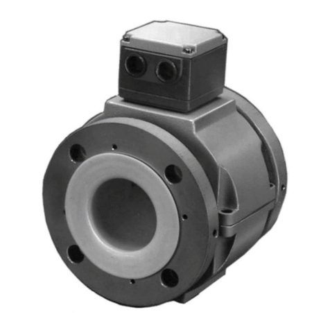
ABB 10DX3111G User manual

INSTRUCTION MANUAL
FLOW PRODUCTS
10DX3111G
Sizes 30" through 78"
MODEL 10DX3111G MAGNETIC FLOWMETER
PN24968
ABB Instrumentation

The following is a trademark of E.I. DuPont de Nemours & Co.:
NEOPRENE
The following is a trademark of Haynes International Inc.:
HASTELLOY
The following is a trademark of International Nickel Co., Inc.:
MONEL
WARNING notices as used in this manual apply to hazards or unsafe practices which could result
in personal injury or death.
CAUTION notices apply to hazards or unsafe practices which could result in property damage.
NOTES highlight procedures and contain information which assist the operator in understanding
the information contained in this manual.
All software, including design, appearance, algorithms and source codes,
is copyrighted and owned by ABB Automation Inc. or its suppliers.
WARNING
POSSIBLE PROCESS UPSETS
Maintenance must be performed only by qualified personnel and only
after securing equipment controlled by this product. Adjusting or
removing this product while it is in the system may upset the process
being controlled. Some process upsets may cause injury or damage.
NOTICE
The information contained in this document is subject to change without
notice.
ABB Automation Inc., its affiliates, employees, and agents, and the
authors of and contributors to this publication specifically disclaim all
liabilities and warranties, express and implied (including warranties of
merchantability and fitness for a particular purpose), for the accuracy,
currency, completeness, and/or reliability of the information contained
herein and/or for the fitness for any particular use and/or for the
performance of any material and/or equipment selected in whole or part
with the user of/or in reliance upon information contained herein.
Selection of materials and/or equipment is at the sole risk of the user of
this publication.
This document contains proprietary information of ABB Automation Inc.,
and is issued in strict confidence. Its use, or reproduction for use, for the
reverse engineering, development or manufacture of hardware or software
described herein is prohibited. No part of this document may be
photocopied or reproduced without the prior written consent of ABB
Automation Inc.
Copyright 2000 ABB Automation Inc. [January 2000]

TABLE OF CONTENTS
1.0 INTRODUCTION . . . . . . . . . . . . . . . . . . . . . . . . . . . . . . . . . . . . . . . . . . . . . . . . . 1-1
1.1 General . . . . . . . . . . . . . . . . . . . . . . . . . . . . . . . . . . . . . . . . . . . . . . . . . . . . . . . . . . . . . . . . . . . . . . . 1-1
1.1.1 Description. . . . . . . . . . . . . . . . . . . . . . . . . . . . . . . . . . . . . . . . . . . . . . . . . . . . . . . . . . . . . . . 1-1
1.1.2 Construction. . . . . . . . . . . . . . . . . . . . . . . . . . . . . . . . . . . . . . . . . . . . . . . . . . . . . . . . . . . . . . 1-1
1.2 Model Number Breakdown . . . . . . . . . . . . . . . . . . . . . . . . . . . . . . . . . . . . . . . . . . . . . . . . . . . . . . . . 1-3
1.3 Specifications. . . . . . . . . . . . . . . . . . . . . . . . . . . . . . . . . . . . . . . . . . . . . . . . . . . . . . . . . . . . . . . . . . . 1-4
2.0 INSTALLATION . . . . . . . . . . . . . . . . . . . . . . . . . . . . . . . . . . . . . . . . . . . . . . . . . . 2-1
2.1 Inspection . . . . . . . . . . . . . . . . . . . . . . . . . . . . . . . . . . . . . . . . . . . . . . . . . . . . . . . . . . . . . . . . . . . . . 2-1
2.2 Uncrating & Handling. . . . . . . . . . . . . . . . . . . . . . . . . . . . . . . . . . . . . . . . . . . . . . . . . . . . . . . . . . . . . 2-1
2.3 Location . . . . . . . . . . . . . . . . . . . . . . . . . . . . . . . . . . . . . . . . . . . . . . . . . . . . . . . . . . . . . . . . . . . . . . . 2-3
2.4 Mounting . . . . . . . . . . . . . . . . . . . . . . . . . . . . . . . . . . . . . . . . . . . . . . . . . . . . . . . . . . . . . . . . . . . . . . 2-4
2.4.1 Orientation . . . . . . . . . . . . . . . . . . . . . . . . . . . . . . . . . . . . . . . . . . . . . . . . . . . . . . . . . . . . . . . 2-4
2.4.2 Pipe Connections. . . . . . . . . . . . . . . . . . . . . . . . . . . . . . . . . . . . . . . . . . . . . . . . . . . . . . . . . . 2-5
2.5 Electrical Connections . . . . . . . . . . . . . . . . . . . . . . . . . . . . . . . . . . . . . . . . . . . . . . . . . . . . . . . . . . . 2-10
2.5.1 Grounding Procedure . . . . . . . . . . . . . . . . . . . . . . . . . . . . . . . . . . . . . . . . . . . . . . . . . . . . . 2-10
3.0 PRINCIPLE OF OPERATION. . . . . . . . . . . . . . . . . . . . . . . . . . . . . . . . . . . . . . . . 3-1
3.1 Basic Operating Principle . . . . . . . . . . . . . . . . . . . . . . . . . . . . . . . . . . . . . . . . . . . . . . . . . . . . . . . . . 3-1
3.1.1 Signal Voltage Generation . . . . . . . . . . . . . . . . . . . . . . . . . . . . . . . . . . . . . . . . . . . . . . . . . . . 3-1
3.1.2 Magnet Coil Drive Circuits . . . . . . . . . . . . . . . . . . . . . . . . . . . . . . . . . . . . . . . . . . . . . . . . . . . 3-2
3.2 Operating Characteristics . . . . . . . . . . . . . . . . . . . . . . . . . . . . . . . . . . . . . . . . . . . . . . . . . . . . . . . . . 3-4
3.2.1 Fluid Variables . . . . . . . . . . . . . . . . . . . . . . . . . . . . . . . . . . . . . . . . . . . . . . . . . . . . . . . . . . . . 3-4
3.2.1.1 Fluid Conductivity . . . . . . . . . . . . . . . . . . . . . . . . . . . . . . . . . . . . . . . . . . . . . . . . . . . 3-4
3.2.1.2 Fluid Temperature . . . . . . . . . . . . . . . . . . . . . . . . . . . . . . . . . . . . . . . . . . . . . . . . . . . 3-4
3.2.1.3 Other Fluid Variables . . . . . . . . . . . . . . . . . . . . . . . . . . . . . . . . . . . . . . . . . . . . . . . . . 3-4
3.2.2 Metering Characteristics . . . . . . . . . . . . . . . . . . . . . . . . . . . . . . . . . . . . . . . . . . . . . . . . . . . . 3-4
4.0 MAINTENANCE . . . . . . . . . . . . . . . . . . . . . . . . . . . . . . . . . . . . . . . . . . . . . . . . . . 4-1
4.1 General . . . . . . . . . . . . . . . . . . . . . . . . . . . . . . . . . . . . . . . . . . . . . . . . . . . . . . . . . . . . . . . . . . . . . . . 4-1
4.2 Routine Maintenance. . . . . . . . . . . . . . . . . . . . . . . . . . . . . . . . . . . . . . . . . . . . . . . . . . . . . . . . . . . . . 4-1
4.3 Trouble-Shooting . . . . . . . . . . . . . . . . . . . . . . . . . . . . . . . . . . . . . . . . . . . . . . . . . . . . . . . . . . . . . . . . 4-2
4.3.1 Magnet Coils . . . . . . . . . . . . . . . . . . . . . . . . . . . . . . . . . . . . . . . . . . . . . . . . . . . . . . . . . . . . . 4-2
4.3.2 Electrodes. . . . . . . . . . . . . . . . . . . . . . . . . . . . . . . . . . . . . . . . . . . . . . . . . . . . . . . . . . . . . . . . 4-3
4.3.3 Electrode Disassembly, Inspection and Replacement. . . . . . . . . . . . . . . . . . . . . . . . . . . . . . 4-3
4.3.3.1 Electrode Inspection . . . . . . . . . . . . . . . . . . . . . . . . . . . . . . . . . . . . . . . . . . . . . . . . . . 4-4
4.3.3.2 Electrode Replacement . . . . . . . . . . . . . . . . . . . . . . . . . . . . . . . . . . . . . . . . . . . . . . . 4-5
10DX3111G INSTRUCTION MANUAL
i
FIGURE LIST
FIGURE 1-1. CUT-AWAY VIEW OF MAGNETIC FLOWMETER . . . . . . . . . . . . . . . . . . . . . . . . . . . . . 1-2
FIGURE 1-2. CONDUCTIVITY GRAPH . . . . . . . . . . . . . . . . . . . . . . . . . . . . . . . . . . . . . . . . . . . . . . . . . 1-6
FIGURE 2-1. PROPER HOISTING TECHNIQUE . . . . . . . . . . . . . . . . . . . . . . . . . . . . . . . . . . . . . . . . . 2-1
FIGURE 2-2. RECOMMENDED PIPING CONNECTIONS . . . . . . . . . . . . . . . . . . . . . . . . . . . . . . . . . . 2-4
FIGURE 2-3. OUTLINE DIMENSIONS, ACCIDENTALLY & CONTINUOUSLY SUBMERSIBLE
METERS (IP67 & IP68), SIZES 30" THROUGH 54". . . . . . . . . . . . . . . . . . . . . . . . . . . . 2-6
FIGURE 2-4. OUTLINE DIMENSIONS, ACCIDENTALLY & CONTINUOUSLY SUBMERSIBLE
METERS (IP67 & IP68), SIZES 60" THROUGH 78". . . . . . . . . . . . . . . . . . . . . . . . . . . . 2-7
FIGURE 2-5. OUTLINE & MOUNTING DIMENSIONS, SPLASHPROOF METERS (IP65),
SIZES 30" THROUGH 54". . . . . . . . . . . . . . . . . . . . . . . . . . . . . . . . . . . . . . . . . . . . . . . . 2-8
FIGURE 2-6. OUTLINE & MOUNTING DIMENSIONS, SPLASHPROOF METERS (IP65),
SIZES 60" THROUGH 78". . . . . . . . . . . . . . . . . . . . . . . . . . . . . . . . . . . . . . . . . . . . . . . . 2-9
FIGURE 2-7. GROUNDING PROCEDURE: NON-INSULATED PIPELINE . . . . . . . . . . . . . . . . . . . . 2-11
FIGURE 2-8. USE OF GROUNDING RINGS & GASKETS. . . . . . . . . . . . . . . . . . . . . . . . . . . . . . . . . 2-13
FIGURE 2-9. GROUNDING PROCEDURE: INSULATED PIPELINE . . . . . . . . . . . . . . . . . . . . . . . . 2-14
FIGURE 2-10. WIRE IDENTIFICATION FOR CONTINUOUS SUBMERGENCE METERS . . . . . . . . 2-15
FIGURE 2-11. TERMINAL IDENTIFICATION FOR SPLASHPROOF METERS. . . . . . . . . . . . . . . . . 2-16
FIGURE 3-1. BASIC OPERATING PRINCIPLE . . . . . . . . . . . . . . . . . . . . . . . . . . . . . . . . . . . . . . . . . . 3-1
FIGURE 3-2. FLUID AND METERING CONDITIONS. . . . . . . . . . . . . . . . . . . . . . . . . . . . . . . . . . . . . . 3-5
FIGURE 4-1. DISASSEMBLY OF ELECTRODE ASSEMBLIES . . . . . . . . . . . . . . . . . . . . . . . . . . . . . 4-5
10D1465 Sizes 30" - 78"
ii

SAFETY SUMMARY
GENERAL
WARNINGS POSSIBLE PROCESS UPSETS. Maintenance must be performed
only by qualified personnel and only after securing equipment
controlled by this product. Adjusting or removing this product
while it is in the system may upset the process being controlled.
Some process upsets may cause injury or damage.
RETURN OF EQUIPMENT. All equipment being returned to ABB
Instrumentation for repair must be free of any hazardous materials
(acids, alkalis, solvents, etc.). A Material Safety Data Sheet (MSDS)
for all process liquids must accompany returned equipment. Con-
tact ABB Instrumentation for authorization prior to returning
equipment.
INSTRUCTION MANUALS. Do not install, maintain or operate this
equipment without reading, understanding and following the
proper ABB Instrumentation instructions and manuals, otherwise
injury or damage may result.
ELECTRICAL SHOCK HAZARD. Equipment powered by AC line
voltage presents a potential electric shock hazard to the user.
Make certain that the system power is disconnected from the oper-
ating branch circuit before attempting electrical interconnections
or service.
SPECIFIC
WARNINGS Equipment powered by an AC line voltage presents a potential
electric shock hazard to the user. Make certain that the system
power input leads are disconnected from the operating branch
circuit before attempting electrical interconnections or service.
(pg. 4-2)
Do not inspect electrodes unless pipe is de-pressurized and
drained. (pg. 4-3)
Do not attempt electrode inpection or replacement with a filled or
pressurized pipeline. Personal injury may result from such prac-
tice. (pg. 4-4)
SPECIFIC
CAUTIONS Never allow support for the Magnetic Flowmeter to bear upon the
inner surface of the meter pipe section inasmuch as the liner may
become damaged. Do not lift the meter by the electrode bosses.
(pg. 2-2)
Excercise extreme care when withdrawing electrode from its seat
so that little or no tension is exerted on the connecting electode
wire. If this wire should break within the meter pipe, the meter is
not repairable. (pg. 4-6)
10DX3111G INSTRUCTION MANUAL
I

GÉNÉRAUX
AVERTISSEMENTS PROBLÈMES POTENTIELS. La maintenance doit être réalisée
par du personnel qualifié et seulement après avoir sécurisé
les équipements contrôlés par ce produit. L’ajustement ou le
démontage de ce produit lorsqu’il est lié au système peut
entraîner des dysfonctionnements dans le procédé qu’il con-
trôle. Ces dysfonctionnements peuvent entraîner des bles-
sures ou des dommages.
RETOUR D’ÉQUIPEMENT. Tout débitmètre et(ou) convert-
isseur retourné à ABB Instrumentation pour réparation doit
être exempt de toute trace de produit dangereux (acide, base,
solvant, …). Un certificat de sécuritématériel doit être joint
pour tous les liquides utilisés dans le procédé. Contacter
ABB Instrumentation pour autorisation avant renvoi du
matériel.
MANUEL DE MISE EN ROUTE. Ne pas installer, maintenir ou
utiliser cet équipement sans avoir lu, compris et suivi les
instructions et manuels de ABB Instrumentation, dans le cas
contraire il y a risque d’entraîner blessures ou dommages.
RISQUE DE CHOC ÉLECTRIQUE
Les équipements alimentés en courant alternatif constituent
un risque de choc électrique potentiel pour l’utilisateur. As-
surez-vous que les câbles d’alimentation amont sont décon-
nectés avant de procéder àdes branchements, des essais ou
tests.
SPÉCIFIQUES
AVERTISSEMENTS Les équipements alimentés en courant alternatif constituent
un risque de choc électrique potentiel pour l’utilisateur. As-
surez-vous que les câbles d’alimentation amont sont décon-
nectés avant de procéder àdes branchements, des essais ou
tests. (pg. 4-2)
Ne pas inspecter les électrodes sans avoir vidéet dépressur-
iséla tuyauterie. (pg. 4-3)
Ne pas effectuer d’inspection ou de remplacement d’élec-
trode lorsque la tuyauterie est pleine ou sous pression. Des
blessures de personne peuvent résulter d’une telle pratique.
(pg. 4-4)
SPÉCIFIQUES
ATTENTIONS Ne pas laisser un support de débitmètre forcer sur la surface
interne de celui-ci, il pourrait en résulter un dommage sur le
revêtement interne. Ne jamais soulever le débitmètre par les
bossages de protection des électrodes. (pg. 2-2)
Faire très attention en enlevant l’électrode de son emplace-
ment de manière àn’exercer aucune tension mécanique trop
forte afin de ne pas casser le fil de raccordement de l’élec-
trode. Si ce fil est casséle débitmètre est irréparable. (pg.
4-6)
10DX3111G INSTRUCTION MANUAL
II

READ FIRST
WARNING
INSTRUCTION MANUALS
Do not install, maintain, or operate this equipment without
reading, understanding and following the proper ABB
Instrumentation instructions and manuals, otherwise injury
or damage may result.
RETURN OF EQUIPMENT
All Flowmeters and/or Signal Converters being returned to
ABB Instrumentation for repair must be free of any
hazardous materials (acids, alkalis, solvents, etc). A Material
Safety Data Sheet (MSDS) for all process liquids must
accompany returned equipment. Contact ABB
Instrumentation for authorization prior to returning
equipment.
Read these instructions before starting installation;
save these instructions for future reference.
All magnetic flowmeters supplied after March 1992 are provided with a corrosion resistant NEMA 4X
finish. The NEMA 4X rating applies to the meter body and electronics enclosure only. The following
accessories (if supplied) may not meet NEMA 4X unless specifically ordered as NEMA 4X:
•meter flanges
•meter installation hardware: studs, nuts, bolts
•enclosure mounting hardware for pipe or wall mounting
•conduit hardware
This product is painted with a high performance epoxy paint. The corrosion protection provided by
this finish is only effective if the finish is unbroken. It is the users’ responsibility to "touch-up" any
damage that has occurred to the finish during shipping or installation of the product. Special attention
must be given to: meter flange bolting, pipe mounting of electronics, conduit entries and covers that
are removed to facilitate installation or repair. For continued corrosion protection throughout the
product life, it is the users’ responsibility to maintain the product finish. Incidental scratches and other
finish damage must be repaired and promptly re-painted with approved touch-up paint. Provide the
model number and size of your product to the nearest ABB Instrumentation representative to obtain
the correct touch-up paint.
10DX3111G INSTRUCTION MANUAL
III

1.0 INTRODUCTION
1.1 General
1.1.1 Description
The ABB Instrumentation Model 10DX3111 Magnetic Flowmeter is a volumetric liquid flow rate de-
tector that uses as the process transducing method the characteristic of a conductive fluid to gener-
ate an induced voltage when flowing through a magnetic field. The amplitude of the voltage
produced is directly proportional to the flow rate of the metered fluid.
Being a completely obstructionless metering instrument, the ABB Instrumentation Model 10DX3111
Magnetic Flowmeter can be used to meter liquids without regard to heterogeneous consistency and
is as independent of the tendency to plug or foul as the pipeline in which it is mounted. An inher-
ent advantage of obstructionless construction is that pressure losses are reduced to levels occur-
ring in equivalent lengths of equal diameter pipeline. This reduces or conserves pressure source
requirements in new or existing hydraulic lines as compared to other metering methods. The com-
pact size of the meter results in a light-weight unit which requires no additional support other than
that used normally on pipe runs. Short laying lengths minimize the need for altering existing pipe
runs to accommodate metering. A basic construction of non-corrosive wetted parts and a variety
of meter lining materials permit metering of most corrosive and reactant fluids.
Factors such as fluid viscosity and density require no compensation and have no effect on the
measurement accuracy of the Magnetic Flowmeter. Metering limitations are confined to a mini-
mum threshold of electrical conductivity inherent to the fluid being metered. The degree of fluid
conductivity has no effect upon metering accuracy as long as it is greater than this minimum level.
Fluid temperature is limited only to the extent that it may affect fluid conductivity and, like fluid pres-
sure, to the extent that it can not exceed the meter material specification limits.
1.1.2 Construction
The ABB Instrumentation Model 10DX3111 Magnetic Flowmeter, as shown in Figure 1-1, Cut-Away
View, consists of a flanged, carbon steel pipe spool which serves as a meter body. A pair of
arched, oval magnet coils fit on opposite sides of the meter body inner surface. This permeable
metal pipe spool acts as a core or return path for the magnetic field generated by the coils.
The coils are potted within an epoxy-base compound. An insulating interior liner of NEOPRENE or
polyurethane is inserted and turned-out against the flange faces. Two cylindrical electrodes are
mounted diametrically opposed within the central portion of the meter body and are completely in-
sulated from the metal pipe. The end surfaces of the standard electrodes are virtually flush with
the inner surface of the insulating liner and come into contact with the fluid to be metered. Bullet
nosed electrodes are mounted in a similar way; however, these electrodes protrude slightly beyond
the inner surface of the liner. Standard or bullet nosed electrodes are available. The electrodes
are replaceable without removing the meter from the pipeline.
The meter is available in three versions: splashproof, accidental submergence and continuous sub-
mergence.
10DX3111G INSTRUCTION MANUAL
1-1

All outer surfaces of the standard meter, with the exception of flange faces, are sprayed with a rust
prohibitive paint. At special option, these surfaces may be treated with corrosion-resistant epoxy
paint.
FIGURE 1-1. CUT-AWAY VIEW OF MAGNETIC FLOWMETER
10DX3111G INSTRUCTION MANUAL
1-2

1.2 Model Number Breakdown
Refer to the ABB Instrumentation data sheet or data tag on the equipment for the model number of
the instrument furnished. The details of a specific number are shown on the following pages.
10DX3111G INSTRUCTION MANUAL
1-3

1.2.1 Model 10DX3111G Model Number Breakdown
10DX3111 G E _ __ _1A_A____2_
Model
Design Level G
Meter Lay Length
Replacement for 10D1435 & 10D1465 E
Liner Material
Hard Rubber
Soft Rubber
Polyurethane
Neoprene
Linatex
A
B
D
L
P
Size (Inches / mm)
28 / 700
30 / 750
32 / 800
36 / 900
40 / 1000
42 / 1050
44 / 1100
48 / 1200
54 / 1400
60 / 1500
64 / 1600
66 / 1650
72 / 1800
78 / 2000
25
43
26
27
28
29
44
30
31
41
32
42
33
34
Flange Standard/Pressure Rating
AWWA C207 CL B
AWWA C207 CL D
DIN PN10
ANSI CL150
3
4
C
P
Flange Material
Carbon Steel 1
Protector Plates
None Required A
Electrode Type
Flush
Bullet Nose
2
3
10DX3111G INSTRUCTION MANUAL
1-4

1.2.1 Model 10DX3111G Model Number Breakdown (Cont.)
10DX3111 G E _ __ _ 1 A _ _ A _ _ _ 2 _
Electrode Material
316 Stainless Steel
Hastelloy B
Hastelloy C
Titanium
K-Monel
Nickel
Alloy 20
B
C
D
E
G
P
Q
Certification
Standard (None) A
Enclosure Classification
IEC 529 IP65, NEMA 4X
Accidental Submergence. 33 ft H2O/48 H
(10m H2O/48 H NEMA 4X IEC 529 IP67)
Continuous Submergence, IEC529 IP68
33 ft H2O (10 m H2O), Signal Cable Permanently Installed
1
2
5
Fluid Temperature Range
Hard Rubber, Linatex 170oF (77oC) Max.
Rubber, Neoprene, Polyurethane 190oF (88oC) Max.
1
4
Line/ Excitation Frequency
50 Hz / 6 1/4 Hz
60 Hz / 7 1/2 Hz
1
3
Customer Information Language
English w/ Riveted SST Tag 2
Converter Type (Remote Only)
M2
50SD1000
None
1
4
X
10DX3111G INSTRUCTION MANUAL
1-5

1.3 Specifications
Electrical Source
Requirements:
As specified with Converter/Driver
Power Consumption 25 watts maximum
Operating Charac-
teristics:
Minimum Allow-
able Fluid Con-
ductivity
5 microsiemens per centimeter, (See
Figure 1-2, Conductivity Graph)
Metering Range -
Adjustable
0-1.5 through 0-37.5 feet per second (standard pre-
set range of Flow Converter)
Meter Capacity See Standard Volumetric Capacity Table
Reference Voltage 140 millivolts peak-to-peak
Maximum Tem-
perature Limits
NEOPRENE Liner 190°F (88°C)
Polyurethane Liner 190°F (88°C)
Dimensions: See Figures 2-3 through 2-6
Weights(Approximate)
Meter Size
(Inches)
Approx. Weight
(Pounds)
30 1400
36 2000
42 2800
48 3900
54 6000
60 7000
66 8600
72 10600
78 13600
10DX3111G INSTRUCTION MANUAL
1-6

Pressure-Temperature Limits: psi (kPa)
Meter Size
(Inches)
Flange Rating
(ANSI)*
NEOPRENE & Polyurethane
100°F (38°C)
psi (kPa)
190°F (88°C)
psi (kPa)
30 CL150 145 (1000) 135 ( 931)
36 CL150 125 ( 862) 120 ( 827)
42 CL150 140 ( 965) 130 ( 896)
48 CL150 120 ( 827) 110 ( 758)
54 CL150 110 ( 758) 105 ( 724)
60 CL150 100 ( 690) 95 ( 650)
66 CL150 100 ( 690) 95 ( 650
72 CL150 95 ( 650) 90 ( 620)
78 CL150 95 ( 620) 90 ( 620)
NOTE: Values given in parenthesis are for SI equivalent units, eg.,
Temperature = °F (38°C)
Pressure = psig (kPA)
*OD and drilling only.
Materials of Construction
Meter Liner NEOPRENE or Polyurethane
Meter Body carbon steel w/Class 150 flanges (OD & drilling
only)
Flanges carbon steel
Electrodes standard or bullet nose type, 316 stainless steel+
+ Also optionally available in HASTELLOY "C", MONEL, Alloy 20, tantalum, titanium,
HASTELLOY "B" and nickel
10DX3111G INSTRUCTION MANUAL
1-7

CAPACITY TABLE
SIZE
FLOW RANGES
0 TO VALUE TABULATED
CAPACITY SETTINGS
(IF NOT SPECIFIED
BY CUSTOMER)
MINIMUM MAXIMUM
Inches mm gpm m3/h gpm m3/h gpm m3/h
30
36
42
48
54
60
66
72
78
750
900
1100
1200
1400
1500
1700
1800
2000
3630
5370
7400
9400
12100
14800
17900
20200
25600
810
1200
1650
2100
2700
3300
4000
4500
5700
81000
120000
165000
210000
270000
330000
400000
450000
570000
16200
24000
33000
42000
54000
66000
80000
90000
114000
22000
32000
45000
60000
70000
90000
110000
120000
150000
5000
7000
10000
12000
16000
20000
24000
27000
35000
METER CAPACITY (10m/sec)
Each 10DX3111 meter in sizes 30" through 78" is calibrated at the factory and the meter capacity
unique to the individual meter is indicated on a tag attached to the side of the meter body. See the
instructions for the converter in the Converter/Driver for details on programming the converter to
use this meter capacity. Note that this is truly a PROGRAMMABLE factor; do NOT follow con-
verter instructions for using a "constant meter factor".
The range requested by the customer is also marked on the tag attached to the meter.
FIGURE 1-2 . CONDUCTIVITY GRAPH
10DX3111G INSTRUCTION MANUAL
1-8

2.0 INSTALLATION
2.1 Inspection
The Magnetic Flowmeter should be inspected before installation for indications of damage which
may have occurred during shipment. All damage claims should be reported to the shipping agent
involved for equipment shipped F.O.B. job site before installation or operation is attempted. If dam-
age is such that faulty operation is likely to result, it should be brought to the attention of the ABB
Instrumentation Service Department.
2.2 Uncrating & Handling
All ABB Instrumentation Magnetic Flowmeters are shipped with the flanges protected. Lift the Mag-
netic Flowmeter using a winch or block and tackle attached to the lifting lugs as shown in Figure 2-
1. (Meter sizes 54" and smaller have two lifting lugs. Sizes 60" and larger have four lifting
lugs.)The rig must be able to support weights as shown in the Specifications sub-section of the IN-
TRODUCTION and must be long enough to produce an angle of 45°or greater between the sling
line and the metal pipe axis.
FIGURE 2-1. PROPER HOISTING TECHNIQUE
10DX3111 INSTRUCTION MANUAL
2-1

The exposed liner material on the meter flange faces is susceptible to damage if mishandled. Do
not walk the meter on its ends. Always use the protective end covers when the meter is trans-
ported.
CAUTION
Never allow any support for the Magnetic Flowmeter to bear upon the
inner surface of the meter pipe section inasmuch as the liner may
become damaged. Do not lift the meter by the electrode bosses.
The protective wooden flange covers or paper guard caps must be removed for inspection and be-
fore mounting in the pipeline.
10DX3111 INSTRUCTION MANUAL
2-2

2.3 Location
Stray electromagnetic and electrostatic fields normally encountered in most industrial areas will
have no effect upon the operating characteristics of the ABB Instrumentation Magnetic Flowmeter.
It is recommended, however, that the meter not be installed within the immediate proximity of
heavy induction equipment.
In-the-line meter maintenance is minimized with this instrument. Further, as no operating adjust-
ments are required in the ABB Instrumentation Magnetic Flowmeter, servicing accessibility is of
secondary importance unless greasy sludges or liquids bearing insulating materials which tend to
coat pipe walls are to be metered. However, sufficient access room should be allocated to facili-
tate electrical interconnection and permit field replacement of electrodes should the need arise.
The installation site must be provided with a convenient source of power as specified with the Con-
verter/Driver. The line should have a disconnect switch and a suitable fuse or circuit breaker as
given on the interconnection diagram of the receiving instrument instruction bulletin. Further, if the
pipeline is not in itself a good ground, a suitable earth ground must be made available in proximity
to the installation site.
10DX3111 INSTRUCTION MANUAL
2-3

2.4 Mounting
2.4.1 Orientation
The ABB Instrumentation Model 10DX3111 Magnetic Flowmeter may be oriented at any angle in
the pipeline. However, precautions must be taken to assure that the metering tube is filled at all
times during measurement. A vertical installation of the metering tube in a pipeline carrying fluid
upwards assures a filled hydraulic line under low flow rate conditions and also minimizes uneven
wear on the meter lining by abrasive grit. Horizontal installations should be made in a lower seg-
ment of the pipeline to assure a filled meter condition. Further, for horizontal or sloping installa-
tions, the meter should be placed so that the connection bosses are on top to align the meter
electrodes in a lateral plane. Positioning the meter in this way eliminates the possibility of en-
trained air acting as an electrode insulator.
The Magnetic Flowmeter may be mounted in the pipeline without regard to flow direction. If greasy
sludges or insulating materials which tend to coat pipe walls are to be metered, it is recommended
that in addition to standard block valves and bypass line, a clean-out tee be installed as shown in
Figure 2-2 to facilitate meter cleaning without removal or interruption of the process.
FIGURE 2-2. RECOMMENDED PIPING CONNECTIONS
Note that the flowmeter shown in this illustraton is not the meter described in
this instruction bulletin.
10DX3111 INSTRUCTION MANUAL
2-4

2.4.2 Pipe Connections
Standard meter piping connections are made by means of flanges that conform to ANSI standards
in outside diameter and bolt circle. The bearing surfaces of the flanges are insulated with the me-
ter pipe liner. Outline and mounting dimensions for meters specified for continuously submerged
applications are given in Figures 2-3 and 2-4. Figures 2-5 and 2-6 provide outline and mounting di-
mensions for meters used in accidental submergence applications.
It is generally recommended that two pipe spools be installed, one on each end fitting of the Mag-
netic Flowmeter, while it is out of the pipeline in order to minimize the possibility of damage to the
meter pipe and flange liner during mounting.
A pair of the proper gaskets to suit the particular lining option of the meter supplied is included
within the installation kit which accompanies the Magnetic Flowmeter. Before connections are
made, the bearing surfaces of NEOPRENE- or polyurethane-lined meter flanges, their NEOPRENE
gaskets and adjacent pipeline flanges should be thoroughly dusted with talc gasket powder. This is
done to prevent possible damage to the meter lining or gaskets, should the meter be removed from
the line.
If the Magnetic Flowmeter is to be mounted in a non-conductive pipeline or a metal pipeline with an
insulating liner, the user must provide a pair of suitable gaskets between the customer-supplied an-
nular meter grounding rings (discussed under Grounding Procedure, Case 2, below) and the adja-
cent pipeline flange surfaces.
The standard coarse thread flange bolts supplied by the user must be well lubricated and tightened
in even increments around the flange surface. Bolt torque should be limited to that which will pro-
duce a positive seal for the application.
10DX3111 INSTRUCTION MANUAL
2-5
Table of contents
Other ABB Measuring Instrument manuals

ABB
ABB CM-ENS User manual

ABB
ABB ScreenMaster RVG200 User manual

ABB
ABB AnalyzeIT ZMT Series Operating instructions

ABB
ABB CoriolisMaster FCB400 User manual

ABB
ABB WVM Series User manual

ABB
ABB INSITE PRO M COMPACT SCU100 User manual

ABB
ABB K-TEK AccuTrak AT500 User manual

ABB
ABB Comem DTI User manual

ABB
ABB EL3060 Series User manual

ABB
ABB Relion 670 series Instructions for use