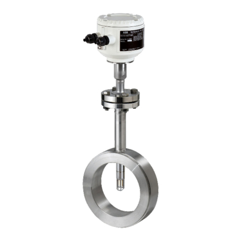
ABB Sensyflow FMT400-VTS User manual

Operating instruction
42/14-36 EN
Thermal Mass Flowmeter
FMT400-VTS, FMT400-VTCS
(Sensyflow VT-S/VT-CS)
for gases, compact configuration

2 Thermal Mass Flowmeter FMT400-VTS, FMT400-VTCS (Sensyflow VT-S/VT-CS) 42/14-36 EN
Thermal Mass Flowmeter
FMT400-VTS, FMT400-VTCS (Sensyflow VT-S/VT-CS)
Operating instruction
Document No. 42/14-36 EN
Edition: 10.2006
Revision 04
Manufacturer:
ABB Automation Products GmbH
Borsigstraße 2
63755 Alzenau
GERMANY
Tel: +49 800 1114411
Fax: +49 800 1114444
© Copyright 2006 by ABB Automation Products GmbH
We reserve the right to technical amendments
This document is protected by copyright. Information in this document is intended only to assist the user in safe
and efficient operation of the equipment. Its contents are not to be reproduced in full or part without prior approv-
al of legal owner.

Content
42/14-36 EN Thermal Mass Flowmeter FMT400-VTS, FMT400-VTCS (Sensyflow VT-S/VT-CS) 3
Content Page
1 Important information in advance . . . . . . . . . . . . . . . . . . . . . . . . . . . . . . . . . . . . . . . . . . . . . . . . 4
Symbols . . . . . . . . . . . . . . . . . . . . . . . . . . . . . . . . . . . . . . . . . . . . . . . . . . . . . . . . . . . . . . . . . . 4
In case of questions . . . . . . . . . . . . . . . . . . . . . . . . . . . . . . . . . . . . . . . . . . . . . . . . . . . . . . . . . 4
2 Application according to designation, general safety instructions . . . . . . . . . . . . . . . . . . 5
2.1 Range of application, application according to designation . . . . . . . . . . . . . . . . . . . . . . . . . . . 5
2.2 General safety instructions . . . . . . . . . . . . . . . . . . . . . . . . . . . . . . . . . . . . . . . . . . . . . . . . . . . . 5
2.2.1 Safe operation . . . . . . . . . . . . . . . . . . . . . . . . . . . . . . . . . . . . . . . . . . . . . . . . . . . . . . . . . . . . . 5
2.2.2 Notes concerning the use in potentially explosive areas . . . . . . . . . . . . . . . . . . . . . . . . . . . . . 6
2.2.3 Notice according to the German Hazardous Material Directive . . . . . . . . . . . . . . . . . . . . . . . . 6
2.2.4 Instructions acc. to Directive 97/23/EC, pressure Devices . . . . . . . . . . . . . . . . . . . . . . . . . . . . 7
3 Design and function . . . . . . . . . . . . . . . . . . . . . . . . . . . . . . . . . . . . . . . . . . . . . . . . . . . . . . . . . . . . 9
3.1 Pipe components . . . . . . . . . . . . . . . . . . . . . . . . . . . . . . . . . . . . . . . . . . . . . . . . . . . . . . . . . . . 9
3.2 Transducer (detecting element) . . . . . . . . . . . . . . . . . . . . . . . . . . . . . . . . . . . . . . . . . . . . . . . 10
4 Mounting and installation . . . . . . . . . . . . . . . . . . . . . . . . . . . . . . . . . . . . . . . . . . . . . . . . . . . . . . 11
4.1 Important information to begin with (check list). . . . . . . . . . . . . . . . . . . . . . . . . . . . . . . . . . . . 11
4.2 Place of installation . . . . . . . . . . . . . . . . . . . . . . . . . . . . . . . . . . . . . . . . . . . . . . . . . . . . . . . . . 11
4.3 Recommended steadying run lengths for inlet run disturbances . . . . . . . . . . . . . . . . . . . . . . 12
4.4 Installation . . . . . . . . . . . . . . . . . . . . . . . . . . . . . . . . . . . . . . . . . . . . . . . . . . . . . . . . . . . . . . . 14
4.5 Dimensional drawings, version for process engineering (dimensions in mm) . . . . . . . . . . . . 15
4.6 Weld-on adapter . . . . . . . . . . . . . . . . . . . . . . . . . . . . . . . . . . . . . . . . . . . . . . . . . . . . . . . . . . . 16
4.6.1 Weld-on adapter for FMT400-VTS (Sensyflow VT-S) transducer . . . . . . . . . . . . . . . . . . . . . 16
4.6.2 Pipe component and weld-on adapter with ball valve . . . . . . . . . . . . . . . . . . . . . . . . . . . . . . . 17
4.7 Integrated hot tap fitting for FMT400-VTS (Sensyflow VT-S) . . . . . . . . . . . . . . . . . . . . . . . . . 18
4.7.1 Technical data for integrated hot tap fittings . . . . . . . . . . . . . . . . . . . . . . . . . . . . . . . . . . . . . 18
4.7.2 Mounting the wafer flange version . . . . . . . . . . . . . . . . . . . . . . . . . . . . . . . . . . . . . . . . . . . . . 19
4.7.3 Mounting the weld-in version . . . . . . . . . . . . . . . . . . . . . . . . . . . . . . . . . . . . . . . . . . . . . . . . . 20
4.7.4 Mounting the transducer with system in operation . . . . . . . . . . . . . . . . . . . . . . . . . . . . . . . . . 21
4.7.5 Disassembling the transducer with system in operation . . . . . . . . . . . . . . . . . . . . . . . . . . . . . 22
4.7.6 Maintenance . . . . . . . . . . . . . . . . . . . . . . . . . . . . . . . . . . . . . . . . . . . . . . . . . . . . . . . . . . . . . . 22
4.8 FMT400-VTCS (Sensyflow VT-CS), hygienic versions . . . . . . . . . . . . . . . . . . . . . . . . . . . . . 24
5 Connecting electrical lines . . . . . . . . . . . . . . . . . . . . . . . . . . . . . . . . . . . . . . . . . . . . . . . . . . . . . 26
5.1 Connecting the power cables . . . . . . . . . . . . . . . . . . . . . . . . . . . . . . . . . . . . . . . . . . . . . . . . . 27
6 Start-up – Safety instructions . . . . . . . . . . . . . . . . . . . . . . . . . . . . . . . . . . . . . . . . . . . . . . . . . . . 28
6.1 Checking the installation . . . . . . . . . . . . . . . . . . . . . . . . . . . . . . . . . . . . . . . . . . . . . . . . . . . . . 28
6.2 Switching on . . . . . . . . . . . . . . . . . . . . . . . . . . . . . . . . . . . . . . . . . . . . . . . . . . . . . . . . . . . . . . 28
7 Changing the configuration . . . . . . . . . . . . . . . . . . . . . . . . . . . . . . . . . . . . . . . . . . . . . . . . . . . . 29
8 Fault messages . . . . . . . . . . . . . . . . . . . . . . . . . . . . . . . . . . . . . . . . . . . . . . . . . . . . . . . . . . . . . . . . 29
9 Maintenance . . . . . . . . . . . . . . . . . . . . . . . . . . . . . . . . . . . . . . . . . . . . . . . . . . . . . . . . . . . . . . . . . . 30
9.1 Cleaning the detecting element. . . . . . . . . . . . . . . . . . . . . . . . . . . . . . . . . . . . . . . . . . . . . . . . 30
9.2 Decommissioning . . . . . . . . . . . . . . . . . . . . . . . . . . . . . . . . . . . . . . . . . . . . . . . . . . . . . . . . . . 30
10 Technical Data . . . . . . . . . . . . . . . . . . . . . . . . . . . . . . . . . . . . . . . . . . . . . . . . . . . . . . . . . . . . . . . . 31
11 Packaging for transport . . . . . . . . . . . . . . . . . . . . . . . . . . . . . . . . . . . . . . . . . . . . . . . . . . . . . . . . 33
12 Declarations of conformity . . . . . . . . . . . . . . . . . . . . . . . . . . . . . . . . . . . . . . . . . . . . . . . . . . . . . 34
12.1 Thermal Mass Flowmeter FMT400-VTS (Sensyflow VT-S) . . . . . . . . . . . . . . . . . . . . . . . . . . 34
12.2 Declaration of conformity FMT...-.. (Sensyflow) - Pipe component. . . . . . . . . . . . . . . . . . . . . 34
Important information in advance
4 Thermal Mass Flowmeter FMT400-VTS, FMT400-VTCS (Sensyflow VT-S/VT-CS) 42/14-36 EN
1 Important information in advance
Symbols In order that you can make the best use of this document and to ensure safety during commissioning, operation
and maintenance of the equipment, please note the following explanation of the symbols used.
Explanation of the symbols used.
As well as the instructions in this document, you must also follow the generally applicable accident prevention
and safety regulations.
If the information in this document is insufficient in any situation, please contact our service department, who will
be happy to help you.
Please read this document carefully before installation and commissioning.
In case of
questions
If you cannot find any information concerning technical questions or malfunctions in these operating instruction,
please apply to one of our external service points or contact our technical user assistance hotline directly. For
all questions concerning the measuring system, please have the calibration certificate readily at hand.
Symbol Signal Word Definitions
DANGER DANGER indicates an imminently hazardous situation which, if not avoided,
will result in death or serious injury.
(High level of risk.)
WARNING WARNING indicates a potentially hazardous situation which, if not avoided,
could result in death or serious injury.
(Medium level of risk.)
CAUTION CAUTION indicates a potentially hazardous situation which, if not avoided,
could result in minor or moderate injury.
(Low level of risk.)
NOTICE NOTICE indicates a potentially harmful situation which, if not avoided,
may result in damage of the product itself or of adjacent objects.
(Damage to property)
IMPORTANT IMPORTANT indicates useful hints or other special information which, if not
observed, could lead to a decline in operating convenience or affect the
functionality.
(Does not indicate a dangerous or harmful situation.)
Sensyflow Hotline Tel: +49 6023 92-3597 or -3267
Fax: +49 6023 92-3210
E-mail: [email protected]m

Application according to designation, general safety instructions
42/14-36 EN Thermal Mass Flowmeter FMT400-VTS, FMT400-VTCS (Sensyflow VT-S/VT-CS) 5
2 Application according to designation, general safety instructions
2.1 Range of application, application according to designation
The thermal mass flowmeter FMT400-VTS/-VTCS is designed for flow rate measurements of gas. It is only suit-
able to be mounted:
• as insertion sensor in a pipe component with flange mounting in pipes of nominal widths from DN 25/1 " to
DN 200/8",
• via weld-on adapter directly in pipes with nominal widths up from DN 150/6" or in pipes with non-circular cross-
sections.
• The standard process temperature range is between -25 °C and +150 °C for process and hygienic types.
Process type sensors with extended temperature range can be operated between -25...+300 °C (metal sensor
-25...+250 °C).
DANGER
•The device is not certified for use in hazardous areas of zone 0 or 1. Zone 2/22 applications are certified
by a manufacturer declaration of conformity.
• Modification of construction details at the device by the user are not permitted.
Any other use is considered improper.
WARNING
For proper use it is required to observe the Technical data section in the data sheets. You will find the data sheets
in section chapter 10 “Technical Data” on page 31 of these operating instructions.
2.2 General safety instructions
2.2.1 Safe operation
The technology of the mass flow meter is state of the art.
The devices were designed, produced and tested in accordance with IEC 1010-1 (corresp. to EN 61010-1 and
DIN VDE 0411 part 1) „Safety reqirements for electrical measurement, control and laboratory equipment“ CE-
certified, and delivered in a safe condition. To maintain this state and guarantee hazard-free operation, all safety
instructions in this manual headed by "DANGER", „WARNING“, „CAUTION“ or „NOTICE“ must be observed.
Otherwise, personnel might be endangered and the mass flow meter itself or other devices and equipment could
be damaged.
Prerequisi-
tes for safe
operation
These operating instructions contain important information about the safe and proper operation of the equip-
ment. Observing these instructions is mandatory for safe operation.
Failure to observe the instructions can cause hazards for life and limb of the user respectively property damages
at the devices or the entire system.
Proper and safe operation of the mass flow meter requires proper transportation and storage, installation and
commissioning by qualified personnel, operation within its design limits, and careful maintenance observing all
information in these operating instructions.
Qualification
of personnel
Only personnel familiar with the installation, commissioning, and maintenance of similar devices and having the
required qualifications for their tasks are allowed to work on the device.
Operator The operator of the plant is fully and solely responsible for proper and workmanlike and, thus, safe operation.
The operator must make sure that the operating instructions have been understood by the target audience.
A copy of the operating instructions must be stored in a suitable place at the usage location of the device at all
times.
Read these operating instructions prior to commissioning, decommissioning, maintaining, or repairing a device.
National
regulations
The regulations, standards, and guidelines mentioned in these operating instructions are valid for Germany.
When using the devices in other countries the appropriate and valid national regulations must be observed.
!
!

Application according to designation, general safety instructions
6 Thermal Mass Flowmeter FMT400-VTS, FMT400-VTCS (Sensyflow VT-S/VT-CS) 42/14-36 EN
Notes and
regulations
to be
observed
Observe
– the contents of these operating instructions and references to other documents and their contents
– the safety instructions attached to the mass flow meter
– the application data indicated in the calibration certificate
– the appropriate and valid safety instructions for the construction and operation of electrical systems
– the appropriate and valid safety instructions for handling gases
– the regulations and directives regarding explosion protection.
During
operation
The operator must commission a qualified electrician to inspect and examine the system at defined intervals.
The examination intervals must be chosen in such a way that any damages that can be expected can be recog-
nised in time.
The examinations must be performed at least every three years.
The examinations can be skipped if the electrical system is continuously monitored by a responsible engineer.
Duties of the operator:
– maintain the system in proper condition
– continuously monitor the system
– execute required maintenance and repair work immediately
– carry out required safety measures.
If the devices are used in areas where dusts can cause explosion hazards, you must clean the devices
frequently.
Use genuine spare parts, only.
2.2.2 Notes concerning the use in potentially explosive areas
Only FMT400-VTS is available in a version authorized for use in zone 2 / zone 22. These devices come supplied
with an EU declaration of conformity (ATEX). For devices authorized for use in zone 2 / zone 22, only the data
and instructions for use stated in the declaration of conformity (ATEX) shall apply.
DANGER
Using the devices in zone 1 / 21 or in zone 0 / 20 is not allowed.
2.2.3 Notice according to the German Hazardous Material Directive
According to the German Waste Disposal Act dated 1986-08-27 (AbfG. §11 Special Waste) the owner of special
waste is responsible for its disposal. According to the German Hazardous Material Directive dated 1986-10-01
(GefStoffV, §17 General Protection Duties) the employer is also obliged to protect his employees. Therefore, we
must point out the following:
a) All flow sensors and/or flow transducers sent to ABB Automation Products GmbH for repair must be free of
any hazardous substances (acids, lyes, solutions, solids).
b) Flow sensors must be flushed and rinsed in order to neutralize hazardous substances. Flow sensors have
cavities. Therefore, the cavity must be neutralized after operation with hazardous materials (refer to German
Hazardous Material Directive, GefStoffV).
c) In case of service or repair, the measures listed in a) and b) must be confirmed in writing. This signed confir-
mation (return report) must be enclosed with the device whenever a device is returned to the factory.
d) Costs arising from increased efforts for handling of contaminated devices and the disposal of hazardous sub-
stances during repair shall be invoiced to the owner of the device!
!

Application according to designation, general safety instructions
42/14-36 EN Thermal Mass Flowmeter FMT400-VTS, FMT400-VTCS (Sensyflow VT-S/VT-CS) 7
2.2.4 Instructions acc. to Directive 97/23/EC, pressure Devices
2.2.4.1 General
• The thermal mass flowmeters FMT400 -VT, -VTCS and the pipe components:
– wafer flange version,
– flange version with integrated partial measuring section and
– weld-on adapter
have been designed, produced and approved in accordance with Directive 97/23/EC for pressure devices.
• The declaration of conformity can be found in the appendix.
• The "FMT400-VT, -VTCS" measuring systems are intended to be used for flow measurement of gaseous
media, only.
• The device may be used for the specific application and under the conditions specified in the order confirma-
tion, only. Otherwise, the device may be impaired, damaged or even destroyed.
• Only those media (fluids) may be measured which – according to the state of the art or the operator's experi-
ence – do not affect the chemical or physical material properties of process-wetted parts that are essential for
operational reliability.
• The threshold for changing stress reversals has been taken from the AD-2000 Leaflet S1, Section 1.4, and
was neither calculated nor checked by us.
• The device must be included in the routine maintenance procedure of the plant and checked accordingly.
• The used materials must be checked by the user for compatibility with the respective application.
• The max. temperature and pressure specified on the rating plate must not be exceeded.
• Prior to mounting or dismounting the pipe components or transducers always make sure that the pipe is fully
depressurized (except when using an easy-change fitting for mounting/dismounting a transducer).
• Prior to starting any installation work on pipes with aggressive, toxic, irritant or noxious substances always
rinse the pipes carefully. When working on the pipes observe the applicable regulations for the prevention of
accidents.
• Do not use damaged pipe components or transducers. Such units must be withdrawn immediately and re-
turned to the vendor for repair.
• Dismounted pipe components or transducers that have been in contact with aggressive, toxic, irritant or nox-
ious substances must be cleaned thoroughly and wrapped and marked accordingly when they are returned to
the vendor.
• If a leakage should occur at a measuring point, the respective point must be put out of service.
• Immediately replace defective gaskets or O-ring seals. Do not re-use.
• Mechanically marking or making alterations to pipe components or sensors can lead to damage to the
components and is thus prohibited. For weld-on adapters, cutting to length and welding on to the pipe are per-
mitted.
• Damage to hot tap fittings due to external fire must be prevented by the system operator.
2.2.4.2 Mounting/Dismounting the pipe component
• When mounting the pipe components, make sure that the flow direction is in accordance with the marking.
• Observe the respective welding regulations when welding in a weld-on adapter. Do not apply more heat than
absolutely necessary to avoid that the sealing face of the mounting flange gets distorted.
• When mounting a pipe component insert a flat flange gasket between the two pipe flanges. The gasket must
be intact and resistant to the conducted substances.
• Prior to mounting always check the pipe component or transducer incl. the gaskets for possible damage.
• Make sure that the pipe components are not twisted when they are mounted.
• Use the appropriate screws with the required strength and dimensions for screwing the flanges together.
• Fasten the flange screws evenly and with the appropriate torque specified for the built-in gasket.
• After mounting the pipe components, close the insertion pipe with an appropriate blind flange with gasket, or
close the existing stop valve, if applicable.

Application according to designation, general safety instructions
8 Thermal Mass Flowmeter FMT400-VTS, FMT400-VTCS (Sensyflow VT-S/VT-CS) 42/14-36 EN
2.2.4.3 Mounting/Dismounting the tranducer
• When mounting the transducer make sure that its specifications are in accordance with the specifications of
the measuring point.
• Exclusively use the flawless, media-resistant O-ring seal delivered with the transducer for mounting. Do not
use a flat packing.
• Insert the O-ring seal into the respective O-ring groove of the connection flange.
• Handle the transducer with care when inserting it into the pipe. Make sure that the sensor unit is not damaged.
• Screw the transducer to the flange of the insertion pipe. Evenly fasten the screws with the appropriate torque.
Torque for the screws supplied: 87 Nm (unlubricated, without the use of sprung washers).
• When using a pipe component with integrated hot tap fitting make sure that the fitting is in dismounting position
before undoing the screws.
2.2.4.4 Potential risks that may occur during operation
• The surfaces of parts run through by hot fluids may get very hot. Do not touch. Otherwise, there is a risk of
being burnt.
• Aggressive fluids may cause corrosion or abrasion which may result in leakage of fluids under pressure.
• The flange or process gaskets may become leaky due to material fatigue. Media under pressure might escape
then.

Design and function
42/14-36 EN Thermal Mass Flowmeter FMT400-VTS, FMT400-VTCS (Sensyflow VT-S/VT-CS) 9
3 Design and function
FMT400-VTS/-VTCS (Sensyflow VT-S/VT-CS) operates on the thermal principle. This measurement method is
based on the principle that gas flowing around a heated body absorbs heat from that body.The result of this flow-
dependent cooling down process is used as a measurement effect. Since the loss of heat depends on the num-
ber of particles reaching the surface of the heated body, it is possible to determine the mass flow directly. It thus
becomes unnecessary to correct pressure and temperature effects.
The measuring systems consist of only the 2 components:
• detecting element and
• pipe component.
Fig. 3-1 and Fig. 3-2 show a schematic representation of the measuring systems
– FMT400-VTS (process version) and
– FMT400-VTCS (hygienic version).
3.1 Pipe components
Pipe components in process version
Pipe components in process version are available in various types for nominal pipe widths from DN 25 to
DN 200. In addition it is possible to integrate the transducer directly into pipes as of DN 150 or into pipes with
non-circular cross-sections using a weld-on adapter.
Fig. 3-1 FMT400-VTS, Process version
Pipe component 1 in
wafer flange design
DN 40 to DN 200
ANSI 1½“ to 8“
(1)
Transducer FMT400-VTS
(1) Centering pin on outlet side
Pipe component 2 as measuring section
DN 25 to DN 50 / ANSI 1“ to 2“
Weld-on adapter from DN 150
(1)
(1)

Design and function
10 Thermal Mass Flowmeter FMT400-VTS, FMT400-VTCS (Sensyflow VT-S/VT-CS) 42/14-36 EN
Pipe components in hygienic version
The pipe components in hygienic version are available for nominal pipe widths from DN 25 to DN 80, either with
FG flanges or threaded pipe connections S in accordance with DIN 11851.
Fig. 3-2 Hygienic version FMT400-VTCS
The pipe components and weld-on adapters guarantee the defined installation of the transducer in the pipeline.
Moreover, they allow simple removal and installation of the transducer for inspection and/or cleaning.
By closing the pipe component with a blind flange, it is possible to use the measuring section even without
installed transducer.
The versions available as standard – depending on the respective nominal width and the desired adaptation –
are shown in chapter 10, “Technical Data”.
3.2 Transducer (detecting element)
The detecting element which is designed as a plug-in sensor contains, apart from the sensor unit, the completely
cast transmitter switching unit installed in the connection head. This is mainly composed of the passive part of
the differential temperature controller for the sensor elements, a memory for all parameter-related measuring
points, the connector for the LCS adapter and the computer for generating flow-specific data.
In addition, a flow-linearized analog signal of 0/4…20 mA (electrically isolated) is directly provided. No special
supply/evaluation device is required.
The transducer is flanged or screwed into pipe component as a plug-in sensor with a centering pin in a defined
manner.
See also chapter 10, “Technical Data”.
Transducer FMT400-VTCS
Pipe component FMT400-VTCS
Centering pin on outlet side
The figure shows process connections
with pipe fitting S acc. to DIN11851.
The transducer and the pipe component
are also available with FG flanges.
FG flanges on the pipe component are
always plain on both sides (without
groove).

Mounting and installation
42/14-36 EN Thermal Mass Flowmeter FMT400-VTS, FMT400-VTCS (Sensyflow VT-S/VT-CS) 11
4 Mounting and installation
4.1 Important information to begin with (check list)
WARNING
Prior to commissioning please pay attention to the following points and read the operating
instructions carefully.
Each measuring system is delivered with a calibration certificate containing all important information on the
respective device such as measuring medium, measuring range, operating temperature range, nominal size,
serial number, ..., ABB Catalog No).
Measuring systems used for gaseous oxygen are given an extra clearance certificate in the form of a Manufac-
turer's certificate.
The following points should be given special attention:
1. Do the operating data of the existing measuring point correspond to the data stated on the calibration
certificate (e.g. medium, operating temperature, pressure, measuring range, ...)?
2. Have the permissible ambient temperatures been kept?
3. Is the pipe component or the weld-on adapter correctly installed (pay attention to the flow direction!)?
4. Have the recommended input and output lengths been complied with?
5. Is the installation between detecting element and pipe component correctly done?
6. Are the used sealings in their correct positions and in good condition?
7. Have the electrical connections UIN (24 V) and IOUT (0/4...20 mA) been correctly made?
4.2 Place of installation
• The installation site must fulfill the requirements stated in the chapter "Technical Data: Operating Conditions,
Environmental Conditions".
• In order to avoid adverse effects on the measurement accuracy, input and output measuring sections should
be provided. These steadying lengths ensure that faults in the flow profile are eliminated before reaching the
actual measuring point on the detecting element.
• Straight, uninterrupted pipes with lengths determined by the type of fault from the input side should be used
as steadying lengths.
• Installations of components which influence the flow rate, such as valves or shut-off fittings should possibly be
located on the output side (behind the measuring point).
• When matching up the detecting element with a weld-on adapter, please read the information in chapter 4.6.
Please make sure that the units are easily accessible when they are installed.
!

Mounting and installation
12 Thermal Mass Flowmeter FMT400-VTS, FMT400-VTCS (Sensyflow VT-S/VT-CS) 42/14-36 EN
4.3 Recommended steadying run lengths for inlet run disturbances
Inlet and outlet runs must be provided to avoid negative effects on the measuring accuracy. These steadying run
lengths make sure that disturbances of the flow profile are eliminated before they can reach the actual measuring
point at the transducer. Straight, undisturbed pipe lengths are used as steadying run lengths, their length de-
pends on the type of the inlet run disturbance.
Recommended steadying lengths according to DIN EN ISO 5167-1
To achieve the stated measuring accuracy, the steadying lengths seen above must be provided.
The inlet and outlet run lengths are stated as multiples of the pipe diameter D.
For combinations of inlet run disturbances, e. g. valve and reducer, you must always consider the longer inlet
run length.
Expansion
X = 15
Reducer
X = 15
90°-elbow
X = 20
Two 90°-elbows
in 1 level
X = 25
Two 90°-elbows
in 2 levels
X = 40
Valve/ slide
X = 50
XD
×
5D
×
Z-18938
Z-18939
< 7°
Z-18940
< 7°
Z-18941
Z-18942
Z-18943
Z-18944

Mounting and installation
42/14-36 EN Thermal Mass Flowmeter FMT400-VTS, FMT400-VTCS (Sensyflow VT-S/VT-CS) 13
In confined spaces at the mounting location the outlet run length can be shortened to 3 ×D. The reduction of the
minimum inlet run length, however, will impact on the achievable accuracy. High repeatability of the measuring
value is still provided.
Under certain circumstances, special calibration can be performed for insufficient steadying lengths. For this
purpose and in individual cases, consult the DKD Calibration Department of ABB Automation Products GmbH
at Alzenau. An on-site adjustment is also possible, if reference flow values are precisely known, by entering a
calibration factor.
The specifications for the steadying sections relate to air and most other measurable gases.
IMPORTANT
For gases with extremely low density (hydrogen, helium) the steadying lengths must be doubled. If type 2
pipe components with integrated flow straighteners are used, then the steadying lengths specified for air
are sufficient.
Components that influence the flow (e. g. valves, shut-off fittings and similar components) should possibly be
mounted at the outlet run length, i. e. behind the measuring point.

Mounting and installation
14 Thermal Mass Flowmeter FMT400-VTS, FMT400-VTCS (Sensyflow VT-S/VT-CS) 42/14-36 EN
4.4 Installation
CAUTION
Safety instructions
When dismounting, with more than 1.1 bar absolute pressure, or with high temperatures or health-
hazardous gases in the pipe, the use of the exchange tool is recommended and obligatory for safety rea-
sons (see chapter 4.7).
Non-observance may lead to severe injuries of persons.
The installation is described using the example of a pipe component of type 1 in intermediate flange version. The
description analogously also applies to a type 2 pipe component and the weld-on adapters.
Fig. 4-1 Schematic illustration of a pipe component 1 with intermediate flange
IMPORTANT
In the case of the type 1 pipe component (intermediate flange version) with ball valve and a nominal width
DN 200 / ANSI 8", transducers with a length of 425 mm must be used.
!
(1) Centering pin
1. The flow direction must agree with the
direction shown by the arrow on the pipe
component.
2. The opening diameter of the sealings
used may not be changed and should on
completion of the component installation
guarantee that the detecting element and
the pipe are absolutely leakproof.
3. The centering pin on the pipe component
(Fig. 4-1) or weld-on adapter must be lo-
cated downstream side (behind the mea-
suring point).
4. Check the supplied O-ring (55 x 3 mm)
between the transducer and the pipe
component / weld-on adapter for signs
of damage prior to installation. Insert the
O-ring exactly into the groove of the
DN 25 flange.
5. All flange screws must be installed
properly.
(1)
Pipe component 1 in
wafer flange design
DN 40 to DN 200
ANSI 1½“ to 8“
Transducer
FMT400-VTS

Mounting and installation
42/14-36 EN Thermal Mass Flowmeter FMT400-VTS, FMT400-VTCS (Sensyflow VT-S/VT-CS) 15
4.5 Dimensional drawings, version for process engineering (dimensions in mm)
Transducer Pipe component1
Wafer flange Pipe component 2
Measuring section Weld-on adapter
L1
B3
h
L2
B2
B1
B4
Centre of
sensor
B3
d2
d1
D1
65
h
Z-18931
B3
L4
L3
h
d1
D4
(DN 25, PN 40)
L5
B3
Z-18933
Pipe 33,7
∅
PN 40
Nom.size L2hD1d1d2D4L3L4L5
DN 25 L1 = 198
B1 = 125
B2 = 80
B3 = Ø115
B4 = 58
269 263 – 28.5 – 115 600 486 –
DN 40 94 43.1 88 150 860 731 –
DN 50 109 54.5 102 165 1000 837 –
DN 80 144 82.5 138 – – – –
DN 100 170 107.1 162 – – – –
DN 150 226 159.3 218 – – – 450
DN 200 293 206.5 285 – – –
> 350 431 425
>700 781 775
ANSI 150 lb, Sch 40 S
1“ L1 = 198
B1 = 125
B2 = 80
B3 = Ø115
B4 = 58
269 263 – 26.6 – 108 560 454 –
1½“ 85 40.9 73 127 864 741 –
2“ 103 52.6 92 154 1003 846 –
3“ 135 78.0 127 – – – –
4“ 173 102.4 157 – – – –
6“ 221 154.2 216 – – – 450
8“ 278 202.7 270 – – –
> 14“ 431 425
> 28“ 781 775
ANSI 300 lb, Sch 40 S
1“ L1 = 198
B1 = 125
B2 = 80
B3 = Ø115
B4 = 58
269 263 – 26.6 – 123.9 560 454 –
1½“ 94 40.9 73 155.4 864 741 –
2“ 110 52.6 92 165.1 1003 846 –
3“ 148 78.0 127 – – – –
4“ 180 102.4 157 – – – –
6“ 249 154.2 216 – – – 450
8“ 307 202.7 270 – – –
> 14“ 431 425
> 28“ 781 775

Mounting and installation
16 Thermal Mass Flowmeter FMT400-VTS, FMT400-VTCS (Sensyflow VT-S/VT-CS) 42/14-36 EN
4.6 Weld-on adapter
4.6.1 Weld-on adapter for FMT400-VTS (Sensyflow VT-S) transducer
When installing the transducer in pipes with larger nominal width or non-round cross-section, the weld-on adapt-
er must be welded to the pipeline under consideration of the following information:
1. The weld-on adapter must have a length L after welding (see Fig. 4-2 and Fig. 4-3)
L = h - ½ × ∅ Doutside with h = 263, 425 or 775 mm (transducer lengths)
– The weld-on adapter must be shortened to the corresponding length before welding. After welding in
place, a few mm of the weld-on adapter can protrude into the pipe (max. 10 mm).
– Observe the pipeline wall thickness and amount of shrinkage when welding!
– The distance h from the flange top edge of the adapter to the pipe center line must be within a tolerance
of ± 2 mm.
2. Rectangularity to the pipe axis must be absolutely kept (max. tolerance: 2°).
3. The centering pin of the adapter must be aligned in flow direction to the pipe axis (at outlet run length, behind
measuring point).
4. After welding the free passage for inserting the transducer must be at least 28 mm (if required, use drill to
clear).
5. Transducer installation:
– Insert the supplied O-ring (55 mm × 3 mm) into the provided groove.
– Push the transducer into the adapter and screw together.
Weld-on adapter for FMT400-VTS (Sensyflow VT-S)
Fig. 4-2 Installation of the weld-adapter
IMPORTANT
Deviations from the stated dimension and position tolerances cause additional measuring uncertainty.
Weld-on adapter
(upon delivery
Required accuracy of mounting
Centric mounting < ± 2 mm
Twist < ± 2°
* This maximum pipe diameter
specification is only valid when
installing thesensor centrically in
the pipe. For larger diameters or
angular ducts a non-centric
sensor position is taken into
account for calibration.
Length h
of the
transducer
(in mm)
Min./max.
outer pipe
diameter
(in mm)
263 100...350
425 > 350...700
775 > 700...1400*
∅d
∅
D
min. 28 mm
h
Z-189341
(1)
L
Direction of flow
Sealing ring groove
(1) Centering pin
on outlet side
∅
33,7
450 mm
Z-189342
(1)
Connection flange DN 25

Mounting and installation
42/14-36 EN Thermal Mass Flowmeter FMT400-VTS, FMT400-VTCS (Sensyflow VT-S/VT-CS) 17
4.6.2 Pipe component and weld-on adapter with ball valve
The ball valve version allows you to mount and dismount the transducer even with low overpressure in the pipe
letting very little gas escape.
The weld-on adapter is mounted as described in chapter 4.6.1.
NOTICE
When welding, it must be ensured that the seals in the ball valve do not overheat.
In there is any doubt, the ball valve must be removed before starting the welding.
When mounting and dismounting the transducer always make sure that the gas pressure inside the pipe is not
as high that the transducer is pressed out of the pipe component or weld-on-adapter. We recommend to use the
integrated hot tap fitting for gas pressures above 1.1 bar abs.
Fully open the ball valve before mounting the transducer. Fit in the appropriate gasket, thoroughly center the
transducer and fasten it.
Prior to dismounting the transducer always check that the pipe is depressurized or that the pressure in the pipe
is low enough to ensure safe dismounting. Only then undo the 4 screws on the DN 25 flange, dismount the trans-
ducer and close the ball valve.
NOTICE
Do not close the ball valve before removing the transducer. Otherwise. the ball may considerably dam-
age the cage or the sensor elements.
Weld-on adapter with ball valve for FMT400-VTS (Sensyflow VT-S)
Fig. 4-3 Installation of the weld-on adapter with ball valve
!
!
(1)
(2)
Z-20233
∅
48.3
540 mm
Connection flange DN 25
Weld-on adapter
(upon delivery)
Length h
of the
transducer
(in mm)
Min./max.
outer pipe
diameter
(in mm)
263 100...150
425 > 150...500
775 > 500...1150*
* This maximum pipe diameter
specification is only valid when
installing the sensor centrically in
the pipe. For larger diameters or
angular ducts a non-centric sen-
sor position is taken into account
for calibration.
∅d
∅
D
min. 28 mm
h
(1)
(2)
Direction of flow
Sealing ring groove
(1) Centering pin on outlet side
(2) ball valve DN 40
D Pipe diameter (outside)
Required accuracy of mounting
Centric mounting < ± 2 mm
Twist < ± 2°

Mounting and installation
18 Thermal Mass Flowmeter FMT400-VTS, FMT400-VTCS (Sensyflow VT-S/VT-CS) 42/14-36 EN
4.7 Integrated hot tap fitting for FMT400-VTS (Sensyflow VT-S)
WARNING
Safety instructions
When dismounting, with more than 1.1 bar absolute pressure, or with high temperatures or health-
hazardous gases in the pipe, the use of the exchange tool is recommended and obligatory for safety
reasons.
Non-observance may lead to severe injuries of persons.
Fig. 4-4 Integrated hot tap fitting, wafer flange and weld-in versions
The integrated hot tap fitting is used instead of the pipe component and weld-on adapter assembly described
above if the sensor must be exchangeable during operation with virtually no gas escaping from the system.
It is recommended to use the hot tap fitting for measurements in main conduits (e.g. compressed air systems)
or for measuring points which otherwise require rinsing prior to removing the sensor. As a rule, hot tap fittings
should be preferred for all systems where, otherwise, the entire system or parts of it must be switched off to
replace a sensor.
!
h = 425 mm
Detail B
50
50
A
B
Hub stroke / mm
20
10
30
40
0 - CLOSE - ZU
50- OPEN - MESSEN
Detail A
Transducer length h
for weld-in version
is always 425 mm
Wafer flange version – sensor
in exchange position
Weld-in version – sensor
in measuring position
Covers for
DN 25 flange Indication of sensor position
(50 mm stroke)
O-ring seal
Bottom edge of lock nut
lock nut
Transducer length h for wafer flange version
h = 263 mm for DN 50 and DN 80
h = 425 mm for DN 100, DN 150 and DN 200

Mounting and installation
42/14-36 EN Thermal Mass Flowmeter FMT400-VTS, FMT400-VTCS (Sensyflow VT-S/VT-CS) 19
4.7.1 Technical data for integrated hot tap fittings
The hot tap fitting is designed for compressive loads of max. 16 bar. To ensure interchangeability with standard
pipe components (Design 1), the wafer flange version (Fig. 4-6) was developed for DIN flanges with a pressure
stage of PN 40. It is available in DN 50 and DN 80 formats for use with sensors with a length of 263 mm. For the
meter sizes DN 100, DN 150 and DN 200, use sensors with a length of 425 mm.
Fig. 4-5 Maximum pressure/temperature values for the integrated hot tap fitting
4.7.2 Mounting the wafer flange version
Fig. 4-6 (left) shows the wafer flange version of the hot tap fitting mounted in the pipeline in disassembly position,
i.e., the guide tube is in its upper end position and seals the Sensyflow opening (right).
The hot tap fitting is sealed on both sides with the flat gaskets against the mounting flange of the pipeline. For
greatest measurement accuracy, it must be centered exactly between the flanges, as it is for conventional pipe
components (see Fig. 4-1). Please observe the proper flow direction (arrow on pipe component).
Fig. 4-6 Hot tap fitting in disassembly position
Permissible pressure load
p_max. of the integrated hot tap fitting
0
2
4
6
8
10
12
14
16
18
0 50 100 150 200 250
T [°C]
p
[b
ar
]
Sensyflow-
opening
Temperature: max. 200 °C
Pressure (abs.): 16 bar - 90 °C
1 bar - 200 °C

Mounting and installation
20 Thermal Mass Flowmeter FMT400-VTS, FMT400-VTCS (Sensyflow VT-S/VT-CS) 42/14-36 EN
4.7.3 Mounting the weld-in version
The weld-in version of the hot tap fitting is available in two overall lengths:
– For meter sizes DN100 / 4" to DN125 / 5" and
– For meter sizes DN150 / 6" to DN300 / 12"
The sensor length is h = 425 mm in both cases.
The installation depth depends on the pipe diameter and is calculated individually.
NOTICE
The components of the hot tap fitting may not be shortened or altered structurally.
Fig. 4-7 Hot tap fitting in measuring position
When welding the hot tap fitting into the pipeline the following points must be taken into consideration:
– Observe pipeline wall strength and degree of shrinkage for welding.
– The distance h from the upper edge of the flange on the fitting to the pipe central axis must be within a
tolerance of ± 2 mm in measuring position.
– Maintain the right angle to the pipe axis (max. tolerance: 2°).
– The centering pin must be aligned with the pipe axis in the flow direction (outflow side, behind the measuring
site (see Fig. 4-7)).
NOTICE
– Make sure that welded joints do not overheat to prevent warping of the seal surface and damage to
the O-rings. You may need to pause and allow the fitting to cool.
!
X
h
Ø50
Y
28
48
Sensyflow VT/iG transducer
Centering pin
(for flow direction)
Flow direction
(Transducer)
Calculating the installation depth
(Hot tap fitting in measuring position):
X = h - (Ø pipe exterior/2)
Y = (Ø pipe exterior/2) - 28
Example:
Transducers of overall length h = 425 mm
Pipe with external diameter of 210 mm
Hot tap fitting is in measuring position
X = 425 mm - (210 mm/2) = 320 mm
!
Other manuals for Sensyflow FMT400-VTS
2
This manual suits for next models
3
Table of contents
Other ABB Measuring Instrument manuals

ABB
ABB ProcessMaster FEP630 series User manual

ABB
ABB C13 User manual

ABB
ABB Endura AZ20 series User manual

ABB
ABB SM1000 User manual

ABB
ABB Comem eOLI22 User manual

ABB
ABB Sensyflow FMT400-VTS Training manual

ABB
ABB RMDE-01 User manual

ABB
ABB GLA133 Series User manual

ABB
ABB K-TEK AccuTrak AT500 User manual

ABB
ABB AquaMaster Explorer User manual