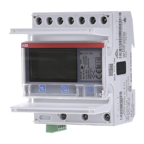
ABB AMTD-1 P User manual

2CSG445001D5601
V A
AMTD-1 P
2CSG213615R4011
AMTD-1-R P
2CSG213645R4011
AMTD-2 P
2CSG213625R4011
AMTD-2-R P
2CSG213655R4011
VLMD P
2CSG213605R4011
VLMD-R P
2CSG213635R4011

[mm]
36
72
51.5
60.5
85.2
68
33
R3
IEC 61554

123456
S2
P2
S1
P1
5A
max
Power Supply
230 V a.c. Signal
input
AMTD-1 P
AMTD-2 P
AMTD-1-R P
AMTD-2-R P
123456
S2
P2
S1
P1
5A
max
Power Supply
230 V a.c. Signal
input
Output
123456
+
–
Power Supply
230 V a.c.
Signal input
60 mV max
123456
+
–
Power Supply
230 V a.c.
Output
Signal input
60 mV max

VLMD P VLMD-R P
123456
L /+
N /–
Power Supply
230 V a.c.
Signal input
600V a.c./d.c.
123456
L /+
N /–
Power Supply
230 V a.c.
Output
Signal input
600V a.c./d.c. max

Digital measurement instruments
Assembly and operating instructions
1
EN
IT
D
F
ES
P
GR
Strumenti digitali con relé
Istruzioni per il montaggio e l’uso
Messgeräte mit digitaler Anzeige
Montageanleitung
Instruments de mesure numériques
Instructions pour le montage et l’utilisation
Instrumentos digitales
Instrucciones de montaje
Instrumentos de medição digital
Instruções de montagem
Ψηφιακά όργανα
Οδηγίες χρήσης

2
Digital instruments
Contents
1. Settings
AMTD-1 P / AMTD-2 P ........................................3
AMTD-1-R P / AMTD-2-R P................................. 4
VLMD P ...............................................................7
VLMD-R P............................................................ 8
2.
AMTD-1-R P / AMTD-2-R P / VLMD-R P functions
Viewing peak values ...........................................13
Min and max relay operation...............................14
Alarm enabling logic ........................................... 14
3. Technical characteristics................................ 15
EN

3
Instructions for the assemblage and the use
1. Settings
AMTD-1 P / AMTD-2 P
A
1
3
2
A
= 5A
A
> 3 sec.
A
A
> 3 sec.
Setting the full scale
1Press and hold the button for at least 3 seconds to access the pro-
gramming menu.
2Press the button briefly to move on to the next item ( = 5A).
3Press and hold the button for at least 3 seconds to select and confirm
the item/parameter.
EN

4
Digital instruments
AMTD-1-R P / AMTD-2-R P
123
Full scale setting [A]
Minimum alarm threshold [A]
Maximum alarm threshold [A]
Alarm tripping delay [sec.]
Alarm cutout hysteresis [%]
Alarm output configuration
Reset min and max values
AA
> 3 sec.
A
> 3 sec.
1Press and hold the button for at least 3 seconds until the display flashes.
2Press the button repeatedly until the indication of the parameter to set
appears.
3Press and hold the button for at least 3 seconds to select the required
full scale.
1. Adjustments and settings
EN

5
Instructions for the assemblage and the use
4 5
A A
> 3 sec.
Functions available
Full scale setting [A]
-= direct insertion without CT
- 15, 20, 25, 40, 60, 100, 150, 200, 250, 400, 600,
999 A full scale values available
4
Press the button repeatedly to view the required value.
5
Press and hold the button for at least 3 seconds to confirm the value selected.
Alarm tripping delay in seconds
- 1-5-10-20-30
-= tripping without delay
Alarm cutout hysteresis in % of the threshold
- 5-10-20-40
Alarm output configuration
- nO/nC
EN

6
Digital instruments
Reset min and max values
- Select the number 5 to reset the values, which is
subsequently confirmed by the displaying three
points
Changing the full scale setting automatically enables the resetting of the
minimum and maximum values, and when you exit from programming
mode will be displayed during the time it takes to recalculate the
values.
AMTD-1-R P / AMTD-2-R P
1. Settings
Maximum alarm threshold [A]
-= alarm function disabled
- CT up to 100 A, resolution 1A
- CT up to 600 A, resolution 10A
Minimum alarm threshold [A]
-= alarm function disabled
- CT up to 100 A, resolution 1A
- CT up to 600 A, resolution 10A
When you select tHH or tHL:
1. the first digit on the right starts flashing
2. press repeatedly to select the required value
3. press and hold the button at least >3sec to confirm
The max selectable value of˜tHH is always lower than the full scale-
value formerly selected.
EN

7
Instructions for the assemblage and the use
VLMD P
1
3
2
V V
> 3 sec.
V
V
> 3 sec.
1Press and hold the button for at least 3 seconds until the display
flashes.
2Press the button briefly to move on to the next item:
- AC = alternating current;
- CC = direct current.
3Press and hold the button for at least 3 seconds to select the item
required.
EN

8
Digital instruments
VLMD-R P
V V
> 3 sec.
V
> 3 sec.
123
Select current to use
Minimum alarm threshold [V]
Maximum alarm threshold [V]
Alarm tripping delay [sec.]
Alarm cutout hysteresis [%]
Alarm output configuration
Reset min and max values
1
Press and hold the button for at least 3 seconds until the display flashes.
2Press the button repeatedly until the indication of the parameter to set
appears.
3Press and hold the button for at least 3 seconds to select the required
full scale.
1. Settings
EN

9
Instructions for the assemblage and the use
4 5
V V
> 3 sec.
Functions available
Select current to use
-= direct current
-= alternating current
4
Press the button repeatedly to view the required value.
5
Press and hold the button for at least 3 seconds to confirm the value selected.
Alarm tripping delay in seconds
- 1-5-10-20-30
-= tripping without delay
Alarm cutout hysteresis in % of the threshold
- 5-10-20-40
Alarm output configuration
- nO/nC
EN

10
Digital instruments
Reset min and max values
- Select the number 5 to reset the values, which is
subsequently confirmed by the displaying three
points
Changing the full scale setting automatically enables the resetting of the
minimum and maximum values, and when you exit from programming
mode will be displayed during the time it takes to recalculate the
values.
Minimum alarm threshold [V]
-= alarm function disabled
- 10 ÷ 590 V full scale values available, resolution 10
V
Maximum alarm threshold [V]
-= alarm function disabled
- 10 ÷ 590 V full scale values available, resolution 10 V
When you select tHH or tHL:
1. the first digit on the right starts flashing
2. press repeatedly to select the required value
3. press and hold the button at least >3sec to confirm
The max selectable value of tHH is always lower than the full scale
value formerly selected.
VLMD-R P
1. Settings
EN

11
Instructions for the assemblage and the use
I
t
Imin
I
t
Imax
1
3
2
V V
V
Displaying and saving minimum and maximum peak values
The peak values recorded (minimum and maximum) are saved in the in-
strument’s nonvolatile memory, and are available after any power failure.
You can reset the peak values by means of the corresponding RES com-
mand in the programming menu.
When you change the value of the CT the maximum and minimum alarm
threshold are automatically disabled.
2. AMTD-1-R P / AMTD-2-R P / VLMD-R P functions
1When you briefly press the front button, the word Lo and the minimum
value measured appear alternately.
2If you press the button again, the word Hi appears with the maximum
value measured.
3Press the button again to return to normal view.
EN

12
Digital instruments
Maximum and minimum relay operation
When the measurement exceeds the threshold value, the relay changes state
and the alarm is tripped after a programmable delay dLY, which appears on
the display alternately with the normal instantaneous measurement.
ALL [ALarm Low] indicates that the minimum threshold has been exceeded
ALH [ALarm High] indicate that the maximum threshold has been exceeded
Even in alarm conditions, pressing the button briefly enables you to view
the minimum and maximum values.
The alarm stops when the measurement returns within the threshold in-
cluding the value of the hysteresis.
Alarm enabling logic
The output from the relay is an open contact type. You can program the
configuration of the relay:
n0 [normally Open] the contact is open when the relay is not energized.
nC [normally Closed] the contact is closed when the relay is not energized.
State of device nO (default) Positive safety nC
Not powered
Powered, alarm not on
Powered, alarm on
2. AMTD-1-R P / AMTD-2-R P / VLMD-R P functions
EN

13
Instructions for the assemblage and the use
3. Technical characteristics
Power supply voltage [V] 230 AC ±10%
Frequency [Hz] 50/60
Max input signal value
AMTD-1 P, AMTD-1-R P [A] 5 AC
VLMD P, VLMD-R P [V] 600 AC/DC
AMTD-2 P, AMTD-2-R P [mV] 60 DC
Full scale values available
on AMTD-1 P and AMTD-1-R P
[A] Indirect insertion by means of CT …/5A
15 20 25 40 60 100 150 200 250 400 600 999
Full scale values available
on AMTD-2 P and AMTD-2-R P
[A] Indirect insertion by means of shunt 60mV
15 20 25 40 60 100 150 200 250 400 600 999
Measurement range
AMTD-1 P, AMTD-1-R P [A] 0…999 AC
VLMD- P, VLMD-R P [V] 0…600 AC/DC
AMTD-2 P, AMTD-2-R P [A] 0…999 DC
Accuracy class
AMTD-1 P, AMTD-1-R P [%] 0,5 ±1 digit
AMTD-2 P, AMTD-2-R P [%] 0,5 ±1 digit
VLMD P, VLMD-R P [%] 0,5 ±1 digit
Memory EEprom
Power consumption [VA] 4
EN

14
Digital instruments
Relay output characteristics
Configuration of contact N.O.
Rated voltage [V] 230 AC
Rated load [A] 16 AC1 - 3 AC15
Contact configuration nO the relay closes in the event of an alarm
nC the relay opens in the event of an alarm,
positive safety
Display LED 3 digits
Storage temperature [°C] -40…70
Working temperature [°C] -10…55
Degree of protection IP20
Modules 3
Standards CEI EN 61010-1
Default values
VLMD-R P
AMTD-1-R P
AMTD-2-R P
Insertion AC ---
Alarm Disabled Disabled
Alarm tripping delay 1 sec 1 sec
Hysteresis 10% 10%
Contact configuration nO nO
3. Technical characteristics
EN

15
Instructions for the assemblage and the use
EN

2
Strumenti digitali
Indice
1. Regolazioni e settaggi
AMTD-1 P / AMTD-2 P ........................................3
AMTD-1-R P / AMTD-2-R P................................. 4
VLMD P ...............................................................7
VLMD-R P............................................................ 8
2. Funzioni AMTD-1-R P / AMTD-2-R P / VLMD-R P
Visualizzazione dei valori di picco........................13
Funzionamento relè di minima e massima...........14
Logica attivazione allarme...................................14
3. Caratteristiche tecniche .................................15
IT
This manual suits for next models
11
Table of contents
Languages:
Other ABB Measuring Instrument manuals

ABB
ABB MR Series Manual

ABB
ABB Aztec AWT440 Training manual

ABB
ABB 8235 Chloride User manual

ABB
ABB B23 User manual

ABB
ABB Totalflow uFLO 6213 User guide

ABB
ABB Navigator 500 Series User manual
ABB
ABB COPA-XM 3000 Series User manual

ABB
ABB XSeriesG4 User manual

ABB
ABB ACF-NT User manual

ABB
ABB IM/SM3000 User manual

ABB
ABB C1900 Series User manual

ABB
ABB SensyMaster FMT230 Installation and operation manual

ABB
ABB AX411 User manual

ABB
ABB DELTAsingle User manual

ABB
ABB AquaMaster 3 User manual

ABB
ABB AnalyzeIT AX460 User manual

ABB
ABB AK102 User manual
ABB
ABB Sensyflow FMT200-D User manual

ABB
ABB Nitrate 8236 User manual

ABB
ABB Relion 630 Series Datasheet