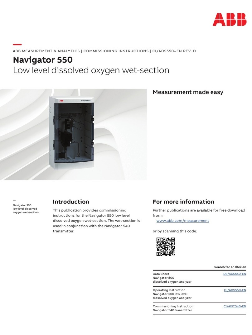
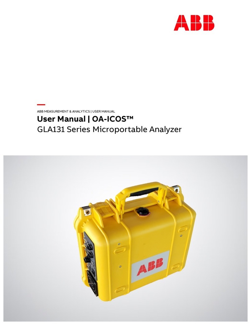
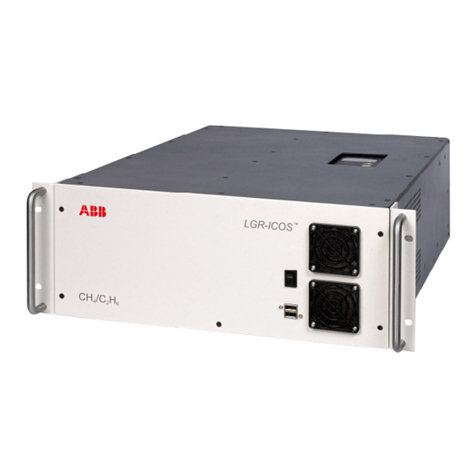
ABB ICOS GLA151 Series User manual

—
ABB MEASUREMENT & ANALYTICS | USER MANUAL
User Manual | ICOS
GLA151 Series QC Portable Analyzers

USER MANUAL | ICOS | INSTRUCTIONS | UM/ICOS-EN REV. B.2
2
Table of Contents
Disclaimer...................................................................................................................................4
Cybersecurity..........................................................................................................................4
Patent..........................................................................................................................................4
Copyright....................................................................................................................................4
Safety...........................................................................................................................................5
Class of Laser Equipment.....................................................................................................5
Certification............................................................................................................................5
WEEE Directive........................................................................................................................5
Labels.......................................................................................................................................6
Operator Safety......................................................................................................................6
Electrical Hazards...................................................................................................................6
Laser Hazards .........................................................................................................................7
SafetyProvisions for a Chemical Spill.................................................................................7
Text Formats and Warning Icons.........................................................................................8
Transportation and Storage of BoxedAnalyzers .................................................................9
Warranty....................................................................................................................................10
Customer Support....................................................................................................................11
1Analyzer Overview........................................................................................................................ 12
Performance Specifications................................................................................................... 12
Ambient Humidity................................................................................................................12
Operating Temperature...................................................................................................... 12
Maximum Altitude................................................................................................................ 12
Power Requirements............................................................................................................ 12
Fuse Ratings.......................................................................................................................... 12
Cable Plugs and Voltage for EC Countries....................................................................... 12
External Dimensions............................................................................................................13
Weight....................................................................................................................................13
Cell Volume............................................................................................................................13
Standard Components............................................................................................................14
Optional Components.............................................................................................................14
Power Connections ................................................................................................................. 17
Emergency Shutdown Procedure.......................................................................................... 17
Data Interface ConnectionPorts...........................................................................................18
Gas Inlet/Outlet Connections................................................................................................19
Warning Labels and Descriptions .........................................................................................20
2Analyzer Setup ............................................................................................................................. 21
Connect the Power Cords....................................................................................................... 21
Connect the DataInterface Connections....................................................................................... 21
Connect the Inlet/Outlet Plumbing Connections........................................................................... 21
3Initialize and Run the Analyzer...................................................................................................22
File System Integrity Check....................................................................................................23
USER MANUAL | ICOS | INSTRUCTIONS | UM/ICOS-EN REV. B.2
3
Thermal Stabilization..............................................................................................................23
The Launch Service Screen.....................................................................................................24
The Auto Launch Screen.........................................................................................................25
Login to Access MenuOptions..............................................................................................26
MainPanel.................................................................................................................................27
UserInterface Control Bar..................................................................................................28
Main Panel Displays.................................................................................................................30
Numeric Display....................................................................................................................30
Alarm Status Display............................................................................................................31
Spectrum Display.................................................................................................................35
TimeChart Display................................................................................................................37
Rate Control..............................................................................................................................38
File Transfer Menu.................................................................................................................. 40
Standard Data File............................................................................................................... 40
Transfer Data Files...............................................................................................................41
Types of directoriesin the local hard drive.........................................................................43
Daily Directory.......................................................................................................................43
Archive Directory..................................................................................................................44
File Transfer Error Screen.......................................................................................................45
Setup Menu...............................................................................................................................46
Time/Files Tab......................................................................................................................47
Calibration Tab.....................................................................................................................50
Laser Adjust Tab...................................................................................................................52
MIU tab...................................................................................................................................54
Analog Output Tab...............................................................................................................55
Service Tab............................................................................................................................57
Shutting Down the Analyzer...................................................................................................58
4Maintenance.................................................................................................................................59
DailyOperation Checklist.......................................................................................................59
Mirror Ring-Down Timeand Maintenance...........................................................................59
Replace the Fuse..................................................................................................................... 60
Appendix A: About Gas Analyzers and Laser Absorption Spectroscopy...............................63
Conventional Laser Absorption Spectroscopy...................................................................63
ABB-LGR’sOff-Axis Integrated-Cavity Output Spectroscopy (Off-Axis ICOS)..............65
Appendix B: Accessing Data Using the Ethernet.......................................................................66
Additional Notes......................................................................................................................67
Appendix C: Wireless Router Setup(Optional)..........................................................................68
Appendix D: Set UpDevices for Remote Access Using VNC Software ..................................73
Appendix E: Multi-Port Inlet Unit (Optional)..............................................................................86
Appendix F: Mirror CleaningProcedure......................................................................................91
Appendix G: Cables ......................................................................................................................105

USER MANUAL | ICOS | INSTRUCTIONS | UM/ICOS-EN REV. B.2
4
Disclaimer
This document contains product specifications and performance statements that may be
in conflict with other ABB publishedliterature, such as product flyers and product catalogs.
All specifications, productcharacteristics, and performance statements included in this
document are suggested specifications only. In case of conflict between product
characteristics in this document and specifications in the official ABB product catalogs, the
latter takes precedence.
ABB reserves theright to make changes to thespecifications of all equipment and
software, andto thecontents of this document, without obligation to notifyany person or
organization of such changes. Every effort has been made to ensurethat the information
contained inthis document is currentandaccurate. Please contact ABB-LGRif you find any
error in this document, so we canmake appropriatecorrections.
Cybersecurity
This product is designed to be connected to and to communicate information and data via
a network interface. It is your soleresponsibility to provide and continuously ensure a
secure connection between the product and your network or any other network (as the
case may be). You shall establish andmaintain anyappropriate measures (suchas, but not
limited to, the installation of firewalls, application of authentication measures, encryption
of data, etc.) to protect the product, the network, its system and the interface against any
kind of security breaches, unauthorized access, interference, intrusion, leakageand/or
theft of data or information.ABB and itsaffiliates are not liable for damagesand/or losses
related to such security breaches, any unauthorizedaccess, interference, intrusion, leakage
and/or theftof data orinformation.
Patent
The analyzertechnology is protected by patents:
7,468,797
6,839,140
6,795,190
6,694,067
Copyright
© 2020 ABB Inc. All rights reserved. No informationcontained inthis document may be
reproducedin any form, in full orin part, without prior written consent fromABB.

USER MANUAL | ICOS | INSTRUCTIONS | UM/ICOS-EN REV. B.2
5
Safety
The following pages provide important safetyprecautions.
Class of Laser Equipment
The analyzeris a Class 1 laser instrument whenthecase cover is closed for normal
operation, and the lock is installed.
Certification
The analyzercertifications are listed in Table 1.
Table 1: Safety Certifications
Symbols
Standards Tested and Met
2004/108/EU (EMC), EN61326-1
Title 21 Code of FederalRegulations, chapter 1, sub-chapter J
WEEE Directive
The analyzeris not subject to WEEE Directive 2002/96/EC(Waste Electricaland Electronic
Equipment) orrelevant national laws (e.g. ElektroGin Germany).
The product must be disposed of at a specialized recycling facility. Do notusemunicipal
garbage collection points. Accordingto theWEEE Directive 2002/96/EC,only products
used in private applications may be disposed of at municipal garbage facilities.

USER MANUAL | ICOS | INSTRUCTIONS | UM/ICOS-EN REV. B.2
6
Labels
The following labels are at specific locations on or in the analyzer to identify
hazardous areas. (Figure 1)
Figure 1: Radiation Labels
These labels are located on the enclosure covering the ICOS cell. The fiber laser is
visible only when theinsulated enclosure is removed from the ICOS cell.
Operator Safety
When the case cover is closedand locked into position, the analyzerruns safely, without
risk to the operator. Modifying theanalyzer to operate with the casecover opencan injure
personnel.
Bypassing the analyzer interlock switch to open the case cover during
analyzer operations can cause serious bodily injury. Even though the
analyzer provides a second layer of protection, such as a laser cover to
prevent the user from the invisible laser beam or any secondary reflection
from the laser on a reflective surface, it is not recommended to modify the
analyzer to operate in an unsafe condition.
Electrical Hazards
The analyzer poses no electrical hazards. Theanalyzer components operateat ≤6.8 V DC.

USER MANUAL | ICOS | INSTRUCTIONS | UM/ICOS-EN REV. B.2
7
Laser Hazards
The analyzeris a Class 1 laser product that complies with:
21 CFR 1040.10 and 1040.11
EN 60825-1:2014
The laser is classified as a Class IIIb when exposed.
Only trained service personnel are authorized to open the housing or
service the laser.
Using this analyzer in a manner not specified by ABB-LGR may result in
damage to the analyzer and render it unsafe to operate.
Only authorized persons may open the analyzer cover or perform internal
maintenance. Contact ABB-LGR for maintenance instructions and
maintenance kits. Make sure the analyzer is unplugged before working
with the internal components. Failure to do so may result in damage to
the analyzer and electric shock.
Safety Provisions for a Chemical Spill
Follow these precautions when dealing with all chemicals:
Keep allchemicalcontainers away from heat, sparks, and open flames.
Use onlyon groundedequipment and with non-sparkingtools.
Store in a cool, dry, and well-ventilated place, away from incompatible materials.
If a spill occurs:
Make sure all handling equipment is electrically grounded.
Mop or wipe up, andthen place all chemical-soaked itemsin containers approved
by the US Department of Transportation (DOT) or the appropriate local regulatory
agency.

USER MANUAL | ICOS | INSTRUCTIONS | UM/ICOS-EN REV. B.2
8
Text Formats and Warning Icons
Text Formats
This section describestext formats and warning icons used inthis manual.
Italicized
text is usedfor emphasis in text andalso to emphasize the names
of screens or text fields.
Bold text is used toshow text that you type in fieldsand also button
choices that you enter.
Warning Icons
Table 2shows and describes the warningicons used in this manual.
Table 2: Warning Icon Descriptions
Icon Meaning
NOTE or
IMPORTANT!
Emphasizes facts and conditions important to analyzer operation.
WARNING!
General Warning Icon: gives general safety information that must be
followed toavoid hazardous conditions.
WARNING! Electrical Warning Icon: warns ofpotential electrical shock hazard.
WARNING!
Laser Warning Icon: warns of potential laser hazard.

USER MANUAL | ICOS | INSTRUCTIONS | UM/ICOS-EN REV. B.2
9
Transportation and Storage of Boxed
Analyzers
When transporting and storing boxed analyzers:
Analyzers may be shipped in non-pressurizedaircraft.
Analyzers are fragile: Do not drop or smash boxed analyzers.
Do not storeanalyzers outside in wetweather.
Do not stack boxesmore than five high.
Analyzers may be safely stored at temperatures between -20oCand +60oC.
Save the original shippingmaterials to use whenreturning theanalyzer to
ABB-LGR if factory service or repair is needed.
Table 3 lists and describes thesafety icons on ABB-LGR shipping boxes. Follow these
instructions when transporting and storingboxed analyzers.
Table 3: Transportation and Storage Icon Descriptions
Icon Meaning
Store your analyzer ina sheltered, dry area. Do not let the box get
wet.
Transport and storetheanalyzer box with thearrows on the box
pointing up.
The analyzeris fragile. Transport carefully. Donot drop the box.

USER MANUAL | ICOS | INSTRUCTIONS | UM/ICOS-EN REV. B.2
10
Warranty
Each ABB-LGRanalyzer iswarranted byABB-LGR to be free from defects in material and
workmanship. However, our sole obligation underthis warranty shall be to repair or
replace any part of the analyzer, which our examination discloses to have been defective in
material orworkmanshipwithout charge and only under the followingconditions:
1. The defects are called to the attention of ABB-LGRin writing within one year after
the shipping date of the analyzer.
2. The analyzerhas not beenmaintained,repaired oraltered by anyonewho was not
approved by ABB-LGR.
3. The analyzerwas used inthe normal, proper, and ordinarymanner and has not been
abused, altered,misused, neglected,involved in anaccidentor damagedby an act
of God or other casualty.
4. The purchaser (whethera distributor or direct customer of ABB-LGR, or a
distributor’scustomer), packs andships or delivers theanalyzer to ABB-LGR’s main
office within 30 days after ABB-LGR has receivedwritten notice of the defect.
Unless otherarrangements have beenmade inwriting, transportation to ABB-LGR
is at customer’s expense.
5. No-charge repair parts may be sent at ABB-LGR’s sole discretion to the purchaser
for installation by purchaser.
6. ABB-LGR’s liabilityis limitedto repair or replace anypart of the analyzer free of
charge if ABB-LGR’s examination disclosesthe part to be defective.
The laws of some locations may not allow the exclusion or limitation on impliedwarranties
or on incidental or consequential damages, so the limitations herein may notapply directly.
This warranty gives you specific legalrights, and you may already have otherrights, which
vary from location to location. All warranties that apply, whether included by this contract
or by law,are limited tothetime period of this warranty, which is a twelve-month period
commencing from the analyzer customership date or eighteen months from the date of
shipment to an ABB-LGR authorized distributor, whichever is earlier.
Further information concerning this warranty may be obtainedby writing or telephoning
the Warranty Managerat ABB-LGR Customer Service.
ABB-LGR provides direct assistance in theuse and application ofall of its analyzers through
email, telephone, and if necessary, in person.
Please contact icos.support@ca.abb.com and your local salesrepresentative for more
details.

USER MANUAL | ICOS | INSTRUCTIONS | UM/ICOS-EN REV. B.2
11
Warranty Returns
If your product is defective, you may returnit during its designated warranty period for a
prompt exchangeor repair. To returna product, pleasecontact your local sales
representativeandABB service support to request a Return Material Authorization (RMA)
number. Requests for refunds and exchanges cannot be processed without a valid RMA
number.
Please have the following information available when requestingan RMA number:
Part Number
Serial Number (Located on the side panel of the analyzer)
Description of the Problem
The company-issued RMAnumber must be prominently displayed onthe return package.
No returns will be accepted collect or C.O.D. On all warranty returns, ABB-LGR will pay the
shipping charges on the return of the merchandise tothecustomer.
Customer Support
ABB provides productsupport services worldwide.To receive product support, either in or
out of warranty, contact the ABB officethat serves your geographical area, or the office
indicated below:
ABB Inc. Measurement & Analytics
3400, rue Pierre-Ardouin
Quebec, (Quebec)G1P 0B2 Canada
Tel: 1 800 858 3847 (North America)
Tel: +1 418 877 2944 (Worldwide)
Fax: +1 418 877 2834
Technical Support: Icos.support@ca.abb.com
Please contact icos.support@ca.abb.com and your local salesrepresentative for more
details.
Please providethe serial number or sales order number of the analyzer.

USER MANUAL | ICOS | INSTRUCTIONS | UM/ICOS-EN REV. B.2
12
1 Analyzer Overview
The ABB-LGR QC Portable Analyzers measure gas concentrations in parts per billion (ppb)
and parts per million (ppm).
This analyzer is a Class 1 laser product.
Performance Specifications
Ambient Humidity
<99% relative humiditynon-condensing
Operating Temperature
5 - 45oC
Maximum Altitude
6,000 Feet
Power Requirements
60 Watts (typical) – 24-30 VDC(battery power)
66 Watts (typical) – 15-230 VAC, 50/60hz (AC adaptor)
120 Watts maximum
Fuse Ratings
32 VAC
10 Amps
Fast-blow fuse
Cable Plugs and Voltage for EC Countries
See page 105.
Always use the power supply cord provided by ABB-LGR. See page 105 for a
description ofpower cords for a specific country.

USER MANUAL | ICOS | INSTRUCTIONS | UM/ICOS-EN REV. B.2
13
External Dimensions
18.5” W x 14” D x 7” H
Weight
15 kg
Cell Volume
345 cc cavity
10 cctubing
Total volume = 355 cc

USER MANUAL | ICOS | INSTRUCTIONS | UM/ICOS-EN REV. B.2
14
Standard Components
This section describesthe analyzer components. Verify thatthese components arrived,
before you begin the setup.
The standardcomponents include:
QC PortableAnalyzer (GLA151 Series)
Analyzer power cord
AC/DC power supply
External in-line filter (push-connect)
Null modem type serial data cable
USB flash drive
Users Guide (this document)
Optional Components
Multiport Inlet Unit, eight or sixteen channels (MIU-8, MIU-16)
oPower cable
o25-pin control signal cable
Maintenancekit (MTN-KIT-64). This recommended kit includes:
oRebuild kit for internal pump
oMirror cleaning kit
o32GB solid state hard drive
DC power pack, with battery (ACC-DCCASE-B)
DC powercase, no battery (ACC-DCCASE)
Battery hook-upkit (ACC-UP-12V)
Ultra-portable analyzer back pack (ACC-UP-BP)
Wireless user interface with iPad (ACC-WIFI-iPad)
Wireless user interface with Nexus7 tablet (ACC-WIFI-Android)
Replacement fuses, in-line filters, side covers (915-9300-0000)
Secondary AC-DC power supply(ACC-UP-AC)
This analyzer has been CE certified using data cables three meters long or
less. Connecting the analyzer using longer data-cables isnot
recommended.

USER MANUAL | ICOS | INSTRUCTIONS | UM/ICOS-EN REV. B.2
15
The wireless user interface will not work if:
The analyzerhas a system failure
The hard drive fails or is corrupted
Battery power to the analyzer is interrupted
If any of these failures occur, you willneed a mouse, keyboard and monitor
to restart the analyzer. Aback up hard drive is recommended.
If you have not receivedall of thesecomponents,contact ABB-LGR at
icos.suppo[email protected].com.

USER MANUAL | ICOS | INSTRUCTIONS | UM/ICOS-EN REV. B.2
16
Figure 2 shows the left side of the analyzer.
Figure 2: Left Panel
Figure 3 shows the right side of the analyzer.
Figure 3: Right Panel

USER MANUAL | ICOS | INSTRUCTIONS | UM/ICOS-EN REV. B.2
17
Power Connections
The power connector is on the left side panel of theanalyzer. (Figure 4)
The analyzercan be powered two ways:
Using theAC/DC power supply to the DC power inlet
Using the battery hook-up kit (Optional)
The battery voltage must be in the range of
11-30 volts DC
. It has a continuous discharge
rate to power 80 watts (or higher).
Figure 4 shows the power entry connector and the power switch.
Figure 4: Power Connections and AC Voltage Selection Switch
The analyzeris equipped witha three-prong power plug. The third prong of
the facility electrical outlets must be grounded. Failureto groundthe third
prong mayresult in electrical damageto the analyzer and electrical shock to
the operator.
Emergency Shutdown Procedure
If the analyzer malfunctions and requires emergency shutdown:
1. Turn off theanalyzer using the left side panel on/off switch. (Figure 2)
2. Unplug the power cord from the analyzer. (Figure 4)
3. Notify trainedservice personnel that the analyzer needs repairor servicing.

USER MANUAL | ICOS | INSTRUCTIONS | UM/ICOS-EN REV. B.2
18
Data Interface Connection Ports
This section describesthe data interface connections as shownin Figure 5. These
connections vary from analyzer to analyzer depending onthe ordered configuration.
USB ports – Usedfor transferring data to a USB memory device, orto connecta
USB keyboard andmouse.
Ethernet port – Connects the analyzer to a localarea network (LAN)and allows
accessto the data directory using an external computer.
Serial port (9 pin D-sub) – For real-time digital measurement output.
Video port (15 pin D-sub) – Connectsan external monitor to theanalyzer.
Analog out port – Provides a DC voltage proportional to the measured gas
concentration. If this output is connectedto an external device, it must be
terminated into a moderate to high impedance (>1kOhm).
MIU port (25-pin data port) –For connecting to a Multiport Inlet Unit (optional).
Figure 5: Data Interface Connection Ports

USER MANUAL | ICOS | INSTRUCTIONS | UM/ICOS-EN REV. B.2
19
Gas Inlet/Outlet Connections
The gas inletandoutlet portsare located on the left side panel of the analyzer. (Figure 6)
Gas to be measured is connected to the ¼”push-connect
INLET
port.
An external In-Line filter is provided, and can be attached to the
INLET
port.
During normaloperation, the pump draws the sample through theanalyzer inlet, and
exhausts the samplethrough the waste port.
The acceptable inlet gas pressure range is 0 to 10 psig.
The ¼” push-connect
WASTE
port may be:
Routed to the facility ventilation system, or
Remain open, expelling non-hazardous gas into the room air.
Figure 6: Gas Inlet/Outlets

USER MANUAL | ICOS | INSTRUCTIONS | UM/ICOS-EN REV. B.2
20
Warning Labels and Descriptions
This section describes the warning labels shown on theanalyzer.
Table 4 gives a description ofthewarning labels.
Figure 7 shows the location of the labels on the analyzer.
Table 4: Warning Labels and Descriptions
Label
Description
The laser is rated Class 3 (invisible laser radiation) when the
housing is open.
Only trained maintenance personnel may open the analyzer
housing.
General laserwarning label.
Figure 7: Warning Label Locations
Other manuals for ICOS GLA151 Series
1
Table of contents
Other ABB Measuring Instrument manuals

ABB
ABB JDF300 User manual

ABB
ABB Endura AZ20 series User manual

ABB
ABB 6553 Series User manual

ABB
ABB 8235 Chloride User manual

ABB
ABB ReliaMod RTBCOVER User manual

ABB
ABB VLMD-1-2 User manual

ABB
ABB FMT200-ECO2 User manual

ABB
ABB SensyMaster FMT230 User manual

ABB
ABB Sensyflow iG User manual

ABB
ABB MagMaster User manual

ABB
ABB WaterMaster User manual

ABB
ABB aquamaster s User manual

ABB
ABB SM3000 User manual

ABB
ABB CEMcaptain GAA610-M User manual

ABB
ABB SensyMaster FMT430 User manual

ABB
ABB FV4000-VT4 User manual

ABB
ABB 10DX3111G User manual

ABB
ABB K-TEK AccuTrak AT500 User manual

ABB
ABB Sensyflow FMT400-VTS User manual

ABB
ABB MAG-X 3000 Series User manual