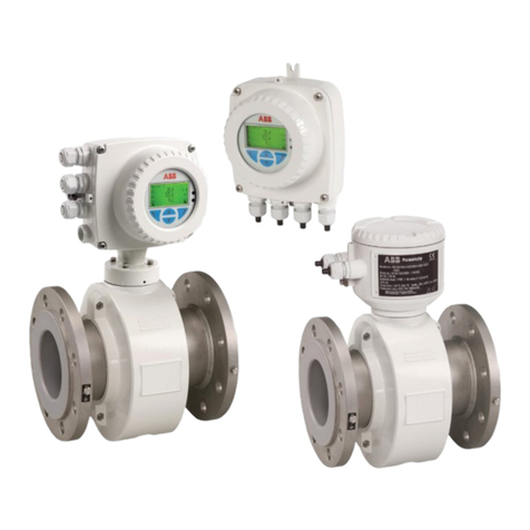
ABB MagMaster MF/F Quick start guide

User Guide IM/MM2WM–EN Rev. A
MagMaster
Electromagnetic flowmeter
MagMaster to WaterMaster
electronics upgrade
Introduction
These instructions describe how to upgrade an existing
MagMaster MF/F flowmeter (DN80 to DN1600)
installation with remote transmitter for use with the new
remote WaterMaster transmitter.
This guide should be read in conjunction with the
following publications:
– WaterMaster FET100 User Guide, OI/FET100–EN
– WaterMaster Programming Guide, IM/WMP
SP033 Adam Street Wynnum SPS - WaterMaster - Electromagnetic Flowmeter -
OIML R49 Class 1 450mm - User Guide
Q-Pulse Id: VM486
Active: 08/04/2016
Page 1 of 12

The Company
We are an established world force in the design and manufacture of instrumentation for industrial process control,
flow measurement, gas and liquid analysis and environmental applications.
As a part of ABB, a world leader in process automation technology, we offer customers application expertise, service
and support worldwide.
We are committed to teamwork, high quality manufacturing, advanced technology and unrivalled service and
support.
The quality, accuracy and performance of the Company's products result from over 100 years experience, combined
with a continuous program of innovative design and development to incorporate the latest technology.
Quality Control
The UKAS Calibration Laboratory No. 0255 is just one of the ten flow calibration plants operated by the Company
and is indicative of our dedication to quality and accuracy.
UKAS Calibration Laboratory No. 0255
SP033 Adam Street Wynnum SPS - WaterMaster - Electromagnetic Flowmeter -
OIML R49 Class 1 450mm - User Guide

Q-Pulse Id: VM486
Active: 08/04/2016
Page 2 of 12

MagMaster
Electromagnetic flowmeter Contents
IM/MM2WM–EN Rev. A 1
Contents
1 Electrical Installation ....................................................................................................................... 2
1.1 Configuration DIP Switches ..................................................................................................... 2
2 MagMaster Sensor Cable ................................................................................................................ 3
2.1 MagMaster Sensor Cable Wiring to WaterMaster Transmitter .................................................. 3
2.1.1 Sensor Coil Resistance .................................................................................................. 3
3 Programming & Configuration ........................................................................................................ 4
3.1 Accessing the Programming Menus ........................................................................................ 4
3.2 Programming Menu – Sensor Setup ........................................................................................ 4
SP033 Adam Street Wynnum SPS - WaterMaster - Electromagnetic Flowmeter -
OIML R49 Class 1 450mm - User Guide
Q-Pulse Id: VM486
Active: 08/04/2016
Page 3 of 12

MagMaster
Electromagnetic flowmeter 1 Electrical Installation
2IM/MM2WM–EN Rev. A
1 Electrical Installation
Install the WaterMaster transmitter in accordance with User Guide, OI/FET100–EN.
1.1 Configuration DIP Switches
Remove the transmitter cartridge as detailed in the User Guides, OI/FET100–EN.
The transmitter backplane PCB contains 3 DIP switches as shown in Fig. 1.1.
For retrofit applications the flowmeter sensor memory, that contains all the sensor-related calibration factors
and settings, is not present on the older MagMaster style of flowmeter sensors. For these flowmeters this
'sensor memory' is switched to use the fitted memory on the backplane PCB of the WaterMaster. This
must be turned on using SW3.
SW3 – Defines the 'Sensor Memory' EEPROM location
OFF= Remote sensor memory
ON = Use Integral transmitter sensor memory
For WaterMaster electronics working with MagMaster sensors (also called 'Retrofit' units) set the DIP
switches as shown in Fig. 1.2. Leave SW1 & SW2 unaltered as they are not part of the retrofit upgrade
detailed here.
Note. These upgrade instructions and the use of WaterMaster with existing MagMaster sensors is
supported only on the MF/F product code style of sensors, not the MF/E type.
Fig. 1.1 Configuration DIP Switches
Fig. 1.2 Configuration DIP Switches
Note. The backplane-fitted 'sensor memory' enables the transmitter cartridge to be changed in a repair
situation (all the settings are retained on the backplane when a new transmitter cartridge is fitted). If the
transmitter enclosure is replaced for any reason, re-install the new transmitter (refer to OI/FET100–EN)
and perform all of the retrofit procedures detailed in this publication (IM/MM2WM–EN).
Configuration
DIP Switches
SW3 SW2 SW1
OFF
ON
SW1 – Read-only / MID Lock
SW2 – (Future Product)
SW3 – Internal Sensor Memory
DIP Switch Functions
Configuration
DIP Switches
SW3 SW2 SW1
OFF
ON
SP033 Adam Street Wynnum SPS - WaterMaster - Electromagnetic Flowmeter -
OIML R49 Class 1 450mm - User Guide
Q-Pulse Id: VM486
Active: 08/04/2016
Page 4 of 12

MagMaster
Electromagnetic flowmeter 2 MagMaster Sensor Cable
IM/MM2WM–EN Rev. A 3
2 MagMaster Sensor Cable
2.1 MagMaster Sensor Cable Wiring to WaterMaster Transmitter
Check the wiring of the sensor cable carefully to ensure good, clean connections. Ensure there are no stray
strands of wire and all terminals are tight.
Fig. 2.1 Shows the wiring of the sensor cable to the remote WaterMaster electronics.
2.1.1 Sensor Coil Resistance
WaterMaster transmitter requires a minimum sensor coil resistance of 15 for correct operation. The coil
resistance can be measured between M1 and M2 with the meter turned off.
Fig. 2.1 Sensor Cable Connections at Transmitter Terminal Block – Standard System
Caution.
Do NOT reverse the inner / signal [E1, E2] and outer / screen [S1, S2] cores of the coaxial cables.
Ensure the black anti-microphonic layer in the grey and white screened cables is removed.
Note. An alarm on the WaterMaster display indicates if the coil resistance is too low for the WaterMaster
transmitter to operate. For the MF/F flowmeter sensor this alarm should not occur. Contact ABB Service
if it does.
Outer screen
must be
connected to
transmitter case
M1
Red
M2
Yellow 3
Violet
S2
White
(Screen)
S1
Grey
(Screen)
E2
Blue
E1
Pink
SP033 Adam Street Wynnum SPS - WaterMaster - Electromagnetic Flowmeter -
OIML R49 Class 1 450mm - User Guide
Q-Pulse Id: VM486
Active: 08/04/2016
Page 5 of 12

MagMaster
Electromagnetic flowmeter 3 Programming & Configuration
4IM/MM2WM–EN Rev. A
3 Programming & Configuration
3.1 Startup
The first time power is applied the HMI screen displays the following message:
Press 'No'. This screen does not appear on subsequent power up.
3.2 Accessing the Programming Menus
Refer to WaterMaster Programming Guide (IM/WMP) and login at Advanced security level.
3.3 Programming Menu – Sensor Setup
The 'Sensor Setup' programming menu enables the WaterMaster electronics to be 'Retro-Fitted' to
MagMaster MF/F sensors.
For retrofit applications an extra menu (Sensor Setup) appears at the end of the menu tables; it is not
present on factory-calibrated WaterMaster flowmeters. Note that after completing configuration of the
retrofit installation, this menu disappears.
If this menu is not present and you are unable to configure the necessary calibration factors below, contact
ABB Service.
The 'Sensor Setup' menu (while visible) enables the setting of items such as the [Sensor Type], [Sensor
Size] and calibration [Span Ss] and [Zero Sz] at 'Advanced' level access. These items are normally editable
only at 'Service' level and are hidden after setup.
[Sensor Setup]
[Sensor Type] Type of Flow Sensor, set to WM Full Bore:
[Probe]* [DE4]*
[Process]* [DE2]*
[Hygienic]* [Process OIML]*
[WM Reduced Throat]* [Hygienic OIML]*
[WM Full Bore] [No Sensor]*
*Do not use these settings
Note. When [Cal. Status] = Not Complete, alarm appears on the display and 'S110.034
Sensor setup not complete' alarm appears in the active alarms list.
No Yes
Blank Sensor Detected
System Startup
Copy Image From Tx?
Menu
Exit Select
Sensor Setup
SP033 Adam Street Wynnum SPS - WaterMaster - Electromagnetic Flowmeter -
OIML R49 Class 1 450mm - User Guide
Q-Pulse Id: VM486
Active: 08/04/2016
Page 6 of 12

MagMaster
Electromagnetic flowmeter 3 Programming & Configuration
IM/MM2WM–EN Rev. A 5
[Sensor Setup] continued
[Sensor Size (Bore)] Nominal bore size of flow sensor in mm:
[DN1]* [DN65]* [DN760]
[DN1_5]* [DN80] [DN800]
[DN2]* [DN100] [DN900]
[DN3]* [DN125]* [DN1000]
[DN4]* [DN150] [DN1050]
[DN6]* [DN200] [DN1100]
[DN8]* [DN250] [DN1200]
[DN10]* [DN300] [DN1400]
[DN15]* [DN350] [DN1500]
[DN20]* [DN400] [DN1600]
[DN25]* [DN450] [DN1800]*
[DN32]* [DN500] [DN2000]*
[DN40]* [DN600] [DN2200]*
[DN50]* [DN700] [Special]*
*Do not use these settings as they are not supported by the upgrade.
[Sensor Cal Mode] Calibration Mode used for sensor, set to WaterMaster.
[WaterMaster]
[ProcessMaster]*
*Do not use these settings
[Span Ss] Calibration Span of the attached flow sensor – equivalent to MagMaster Cal Fact 1.
1. Refer to Table 3.1, page 6 to calculate WaterMaster Span Ss value from MagMaster Cal Fact 1
(Snsr Fact 1). This Cal Fact 1 is identified on the data label, identified as 'Cal 1'. It is also available on
the meter calibration certificate.
2. Multiply the MagMaster Cal Fact 1 by the 'Cal Fact 1 to Ss Multiplier' to find the Span Ss value.
3. Enter the correct Span Ss % value as calculated.
4. Ensure flow is present in the sensor.
5. If the flow reads in the wrong direction, enter the span as a negative value (for example, –123.45 %
instead of 123.45 %).
[Zero Sz] Calibration Zero Offset of the attached flow sensor – equivalent to MagMaster Cal Fact 2.
This is identified on the MagMaster sensor data label as 'Cal. 2/3/4'. The zero value is the first number
– for example, 'Cal. 2'.
1. Refer to Table 3.1, page 6 to calculate WaterMaster Zero Sz value from MagMaster Cal Fact 2
(Snsr Fact 2).
2. Multiply the MagMaster Cal Fact 2 by the 'Cal Fact 2 to Sz Multiplier' to find the Zero Sz value.
3. Enter the correct Zero Sz value as calculated.
SP033 Adam Street Wynnum SPS - WaterMaster - Electromagnetic Flowmeter -
OIML R49 Class 1 450mm - User Guide
Q-Pulse Id: VM486
Active: 08/04/2016
Page 7 of 12

MagMaster
Electromagnetic flowmeter 3 Programming & Configuration
6IM/MM2WM–EN Rev. A
MF/F DN Cal Fact 1 to Ss
Multiplier
Cal Fact 2 to Sz
Multiplier
80 102.3 0.1
100 102.0 0.1
150 101.9 0.1
200 101.8 0.1
250 103.8 0.1
300 103.1 0.1
350 104.9 0.1
400 104.5 0.1
450 104.0 0.1
500 105.0 0.1
600 105.4 0.1
700 105.4 0.1
760 101.4 0.1
800 101.2 0.1
900 101.9 0.1
1000 101.8 0.1
1050 101.8 0.1
1100 101.8 0.1
1200 101.8 0.1
1400 101.8 0.1
1500 101.8 0.1
1600 101.8 0.1
Table 3.1 WaterMaster Span Ss Values
SP033 Adam Street Wynnum SPS - WaterMaster - Electromagnetic Flowmeter -
OIML R49 Class 1 450mm - User Guide
Q-Pulse Id: VM486
Active: 08/04/2016
Page 8 of 12

MagMaster
Electromagnetic flowmeter 3 Programming & Configuration
IM/MM2WM–EN Rev. A 7
[Sensor Setup] continued
[Trim St] Calibration 'trim' adjustment in % applied to the main span [Span Ss].
Is set to 0.000%.
[Mains Frequency] Frequency of the local AC mains / line supply voltage (for noise rejection).
[50 Hz]
[60 Hz]
Set as per the local AC mains / line supply. It must also be set for DC versions.
[Drive Mode] Coil Excitation mode to be used for flow sensor.
Dependent on sensor size. Refer to table below for correct value to set. If this value is altered, the
WaterMaster transmitter reboots automatically. After reboot, re-login and continue setup.
[Coil Measurement F] Frequency to use for sensor coil diagnostic measurements.
Dependent on sensor size. Ensure the 'Drive Mode' is set first. Refer to Table 3.2 for the correct value
to enter.
Sensor Size Drive Mode Coil
Measurement F
< DN350 5A 40 Hz
DN350 5A 20 Hz
DN400 5A 20 Hz
DN450 5A 20 Hz
DN500 5A 20 Hz
DN600 7A 8 Hz
DN700 7A 8 Hz
DN760 7A 8 Hz
DN800 7A 8 Hz
DN900 7A 8 Hz
DN1000 7A 8 Hz
DN1200 7A 8 Hz
DN1400 7A 8 Hz
DN1600 7A 8 Hz
Table 3.2 Drive Mode and Coil Measurement Frequency
SP033 Adam Street Wynnum SPS - WaterMaster - Electromagnetic Flowmeter -
OIML R49 Class 1 450mm - User Guide
Q-Pulse Id: VM486
Active: 08/04/2016
Page 9 of 12

MagMaster
Electromagnetic flowmeter 3 Programming & Configuration
8IM/MM2WM–EN Rev. A
[Sensor Setup] continued
[Coil Current] The current to be used for sensor coil drive.
All systems using WaterMaster electronics must be set to 180 mA.
[180mA].
[Sensor Calibration]
[First Cal. Date] Date of first calibration.
For retro-fit units set to date on calibration certificate (if known) or set to the date of installing the
WaterMaster Transmitter. The date format can be set to user preferences – refer to IM/WMP.
[Last Cal. Date] Date of last calibration. For retro-fit units set to date of installing WaterMaster
transmitter
[Last Cal. Location] Set to Location of last calibration. Set to Stonehouse.
[Stonehouse] [Warminster]* [Shanghai]* [ ]*
[Gottingen]* [Moorebank]* [Burlington]*
*Do not use these settings
[Sv] Calibration correction factor.
Set to Zero for retro-fit sensors.
0.000
[Sc] Calibration correction factor.
Set to Zero for retro-fit sensors.
0.000
[Cal. Status] Status of calibration settings for this flowmeter.
Only when programming of calibration settings is complete, fully checked and the flowmeter is working
correctly adjust this setting to 'Calibrated'.
The 'Sensor Setup Not Complete' alarm should now disappear.
Upgrade of the MagMaster sensor is now complete.
Further programming or troubleshooting of the flowmeter can be achieved as normal via the keypad (refer
to the WaterMaster Programming Guide, IM/WMP).
Caution. Changing this setting to [Calibrated] causes the 'Sensor Setup' menu to disappear. This
sensor calibration data (type, size, span, zero, etc.) is then LOCKED. Modification is then possible only
by ABB Service engineers.
SP033 Adam Street Wynnum SPS - WaterMaster - Electromagnetic Flowmeter -
OIML R49 Class 1 450mm - User Guide
Q-Pulse Id: VM486
Active: 08/04/2016
Page 10 of 12

Products and customer support
Automation Systems
For the following industries:
— Chemical & Pharmaceutical
— Food & Beverage
— Manufacturing
— Metals and Minerals
— Oil, Gas & Petrochemical
— Pulp and Paper
Drives and Motors
— AC and 6 Drives, AC and DC Machines, AC Motors to
1kV
—Drive Systems
— Force Measurement
— Servo Drives
Controllers & Recorders
— Single and Multi-loop Controllers
— Circular Chart and Strip Chart Recorders
— Paperless Recorders
—Process Indicators
Flexible Automation
— Industrial Robots and Robot Systems
Flow Measurement
— Electromagnetic Flowmeters
—Mass Flowmeters
— Turbine Flowmeters
— Wedge Flow Elements
Marine Systems & Turbochargers
— Electrical Systems
— Marine Equipment
— Offshore Retrofit and Refurbishment
Process Analytics
— Process Gas Analysis
—Systems Integration
Transmitters
—Pressure
—Temperature
— Level
—Interface Modules
Valves, Actuators and Positioners
— Control Valves
—Actuators
—Positioners
Water, Gas & Industrial Analytics Instrumentation
— pH, Conductivity and Dissolved Oxygen Transmitters
and Sensors
— Ammonia, Nitrate, Phosphate, Silica, Sodium,
Chloride, Fluoride, Dissolved Oxygen and Hydrazine
Analyzers
— Zirconia Oxygen Analyzers, Katharometers, Hydrogen
Purity and Purge-gas Monitors, Thermal Conductivity
Customer support
We provide a comprehensive after sales service via a
Worldwide Service Organization. Contact one of the
following offices for details on your nearest Service and
Repair Centre.
UK
ABB Limited
Tel: +44 (0)1453 826661
Fax: +44 (0)1453 829671
USA
ABB Inc.
Tel: +1 215 674 6000
Fax: +1 215 674 7183
Client Warranty
Prior to installation, the equipment referred to in this
manual must be stored in a clean, dry environment,
in accordance with the Company's published
specification.
Periodic checks must be made on the equipment's
condition. In the event of a failure under warranty,
the following documentation must be provided as
substantiation:
— A listing evidencing process operation and alarm
logs at time of failure.
— Copies of all storage, installation, operating and
maintenance records relating to the alleged faulty
unit.
SP033 Adam Street Wynnum SPS - WaterMaster - Electromagnetic Flowmeter -
OIML R49 Class 1 450mm - User Guide
Q-Pulse Id: VM486
Active: 08/04/2016
Page 11 of 12

Contact us
IM/MM2WM–EN Rev. A 12.11
ABB Limited
Process Automation
Oldends Lane
Stonehouse
Gloucestershire GL10 3TA
UK
Tel: +44 1453 826 661
Fax: +44 1453 829 671
ABB Inc.
Process Automation
125 E. County Line Road
Warminster
PA 18974
USA
Tel: +1 215 674 6000
Fax: +1 215 674 7183
www.abb.com
Note
We reserve the right to make technical
changes or modify the contents of this
document without prior notice. With regard
to purchase orders, the agreed particulars
shall prevail. ABB does not accept any
responsibility whatsoever for potential
errors or possible lack of information in this
document.
We reserve all rights in this document and
in the subject matter and illustrations
contained therein. Any reproduction,
disclosure to third parties or utilization of its
contents in whole or in parts – is forbidden
without prior written consent of ABB.
Copyright© 2011 ABB
All rights reserved
SP033 Adam Street Wynnum SPS - WaterMaster - Electromagnetic Flowmeter -
OIML R49 Class 1 450mm - User Guide
Q-Pulse Id: VM486
Active: 08/04/2016
Page 12 of 12
Table of contents
Other ABB Measuring Instrument manuals

ABB
ABB Aztec 600 Color User manual

ABB
ABB Aztec 600 User manual

ABB
ABB IM300-I Quick start guide

ABB
ABB ANR96 User manual

ABB
ABB 8037 User guide

ABB
ABB PROFIBUS FEX100-DP User manual

ABB
ABB Relion 670 series Quick start guide

ABB
ABB 7651 User manual

ABB
ABB VA Master FAM540 Training manual

ABB
ABB FSM4000 Series Installation and operation manual

ABB
ABB 2155 User manual

ABB
ABB EV3 User manual

ABB
ABB ICOS GLA151 Series User manual

ABB
ABB AX410 User manual

ABB
ABB Endura AZ20 series User manual

ABB
ABB ProcessMaster FEP630 series User manual

ABB
ABB ADS420 User manual

ABB
ABB GLA232 Series User manual

ABB
ABB ICOS GLA151 Series User manual

ABB
ABB CoriolisMaster FCM2000 Installation and operation manual