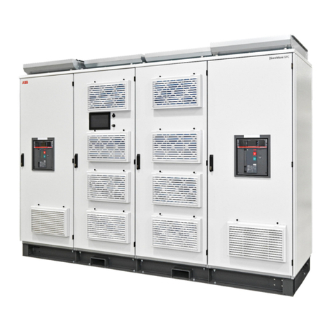
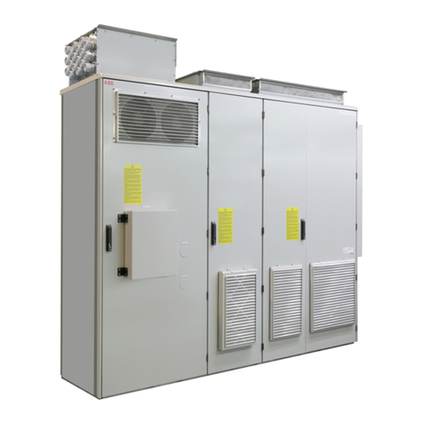
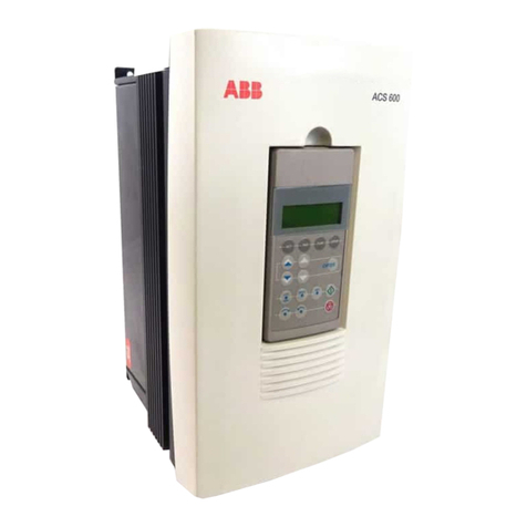
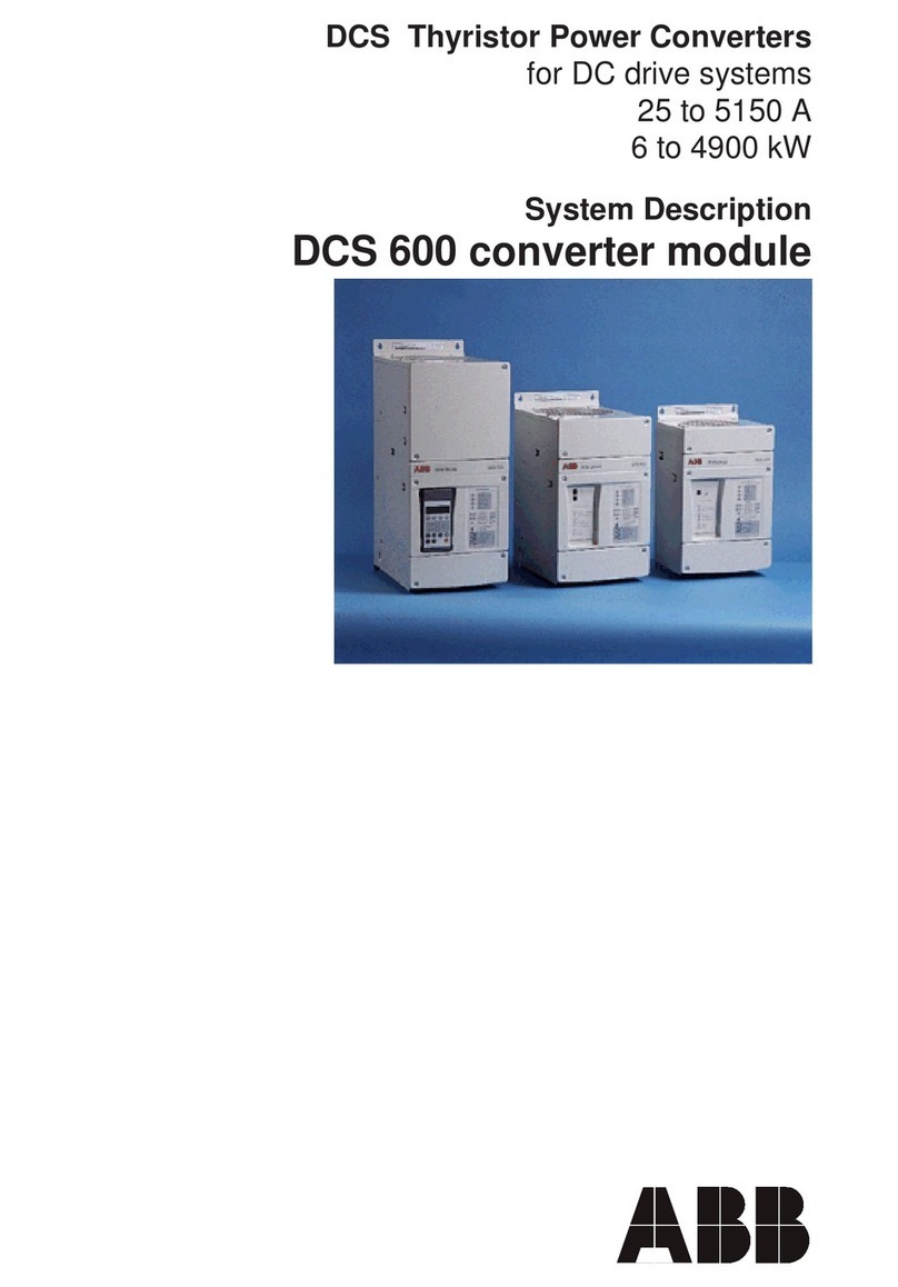
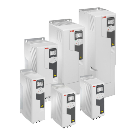
ABB DCS 600 MultiDrive Series User manual

II F i
3ADW000072R0501_DCS600_System_description_e_e
DCS Thyristor Power Converters
for DC Drive Systems
25 to 5200 A
System Description
DCS 600 MultiDrive

II F ii
3ADW000072R0501_DCS600_System_description_e_e
List of contents
II F SYSTEM DESCRIPTION
1 DCS 600 MultiDrive - the power converter II F 1-1
2 DCS 600 MultiDrive components overview II F 2-1
2.1 Environmental conditions .............................................. II F 2-3
2.2 DCS 600 power converter modules .............................. II F 2-4
2.3 DCS 600 overload withstand capability ........................ II F 2-7
2.4 Field Supply .................................................................. II F 2-9
2.5 Options for power converter modules ......................... II F 2-11
In-/output signals ........................................................ II F 2-11
Serial interfaces
Operation by the panel .............................................. II F 2-13
Panel (control and display panel) .............................. II F 2-14
Operation by the PC .................................................. II F 2-15
Drive control ............................................................... II F 2-15
2.6 Options ........................................................................ II F 2-17
Line reactors for armature (DCS600) and
field (DCF600) supply ................................................ II F 2-17
Aspects of fusing for armature circuits and field
supplies of DC drives .............................................. ...II F 2-19
Semiconductor type F1 fuses and fuse holders for
AC and DC power lines ............................................. II F 2-21
Fuses F3.x fuses and fuse holders for 2-phase
field supply ................................................................. II F 2-21
Transformer T3 for field supply .................................. II F 2-22
Commutating reactor ................................................. II F 2-22
Auxiliary transformer T2 for electronic system /
fan supply ................................................................... II F 2-22
Residual current detection ......................................... II F 2-22
EMC filters ................................................................. II F 2-23
3 Overview of Software (Vers. 15.xxx) ......... II F 3-1
3.1 Basic structure of DCS 600 MultiDrive .......................... II F 3-1
3.2 Control modes ............................................................... II F 3-1
3.3 Start, Stop and Fault reactions ..................................... II F 3-2
3.5 Torque control ............................................................... II F 3-4
3.4 Speed control ................................................................ II F 3-4
3.5 Torque control ............................................................... II F 3-4
3.6 HMI (Human Machine Interface) ................................... II F 3-4
3.7 Torque generation ......................................................... II F 3-5
3.7 Software diagrams ........................................................ II F 3-6
4 Connection examples ................................. II F 4-1
How the DCS 600 MultiDrive Documentation Sys-
tem works
This is to give you an overview how the system of
information for DCS 600 MultiDrive converters is
built up. The shaded part indicates the volume within
the total system you are just now working with. In
addition you see all other available documents for the
same system.
System Description
DCA 600 Enclosed
3ADW000121
Volume II F1
Oper. Instructions
DCS(F) 600
3ADW000080
Volume IV F
SW Description
DCS(F) 600
3ADW000076
Volume V F
Technical Data
3ADW000165
Volume III
System Description
DCS(F) 600
3ADW000072
Volume II F
Installation Man.
DCA 600 ...
3ADW000091
Volume VI F1
Service Manual
DCS 500/600
3ADW000093
Volume VI A
12-Pulse Manual
DCS 600
3ADW000115
Volume II F2

II F 1-1
3ADW000072R0501_DCS600_System_description_e_e
1 DCS 600 MultiDrive - the power converter
❖state-of-the-art technology
❖flexible design
❖user-friendly
Unit range
The range comprises of 5 sizes, C1, C2, A5, A6 and A7.
We can deliver both modules and standard cubicles.
Basic hardware components
❋Thyristor bridge(s) (from size A5 with installed
branch fuses)
❋Temperature monitor for the thyristor bridge(s)
❋Fan
❋Integrated power supply for the electronics
❋Microprocessor board
❋AMC(Application MotorControl)boardwithDSP
(Digital Signal Processor) for drive control and
DDCS link
Additional components integrated in the module
❋Field supply converter
– uncontrolled full wave diode bridge, 6A or
– half-controlled diode/thyristor bridge, 16A
❋Control panel
Moreover, the accessories listed below can be used
to individually customize the drive package in ac-
cordance with the application intended
❋External field supply units
❋12-Pulse parallel configuration
❋12-Pulse serial/sequential configuration
❋Additional I/O boards (isolated)
❋Interface modules for various communication pro-
tocols
❋EMC filter
❋PC programs
C1 - Module DCA cubicle
ABB’s long years of experience with variable-speed DC
drives, plus use of the latest state-of-the-art technolo-
gies, have been combined to create this product. The
DCS 600 MultiDrive contains a complete program
with ratings between 25 A and 5200 A as a power
converter module (in 12-pulse parallel configuration
appr. 10,000 A). It is suitable for all commonly used
three-phase systems.
All our products are CE approved.
The DC drives factory of ABB Automation Products,
Drives Division in Lampertheim has implemented and
maintains a quality management system according to
DIN EN ISO 9001 and an environmental manage-
ment system according to DIN EN ISO 14001.
DCS 600 MultiDrives are approved according to UL
(Underwriters Laboratory).
They also comply with the relevant EMC standards for
Australia and New Zealand and are C-Tick marked.
DCS 600 MultiDrive converter units are suitable for
standard and system drive applications.
Appropriate PC programs ensure that the drives are
engineered for user-friendly operator control.
DIN EN ISO 9001
DIN EN ISO 14001

II F 1-2
3ADW000072R0501_DCS600_System_description_e_e
Design and commissioning tools
DriveWindow
PC program for commissioning and maintenance un-
der Windows®for:
Parameter setting
Fault detection
Trending
Data logger
Fault logger
Local operation (Drives Panel)
CDP 312 removable control and display panel with
plain text display for:
Drive control signal
Parameter setting
Fault detection
Parameter uploading and downloading
Local operation
Monitoring functions
Self-test
Fault logger
Motor protection
In the event of:
• Speed feedback error
• Overtemperature
• Overload
• Overspeed
• Zero speed
• Armature overcurrent
• Armature ripple
• Armature overvoltage
• Minimum field current
• Field overcurrent
• Motor stalled
Power converter protection
• Overtemperature
• Software errors (watchdog function)
Incorrect supply protection
• Mains overvoltage and undervoltage
• Auxiliary undervoltage
• Incorrect mains phase sequence (only inform.)
Basic functions
All units are provided with the same digital control
boards and software. The DCS 600 MultiDrive flexi-
bility allows the user to configure functions of the drive
easily, suitable for different applications. Functions of
the DCS 600 MultiDrive are normally activated by
parameters.
The basic software includes the following options:
• Processing the speed reference with a speed ramp
generator (S-ramp capability, accel/decel ramp)
• Processing the speed feedback
• Speed controller
• Torque reference processing
• Current controller
• Field weakening
• Automatic/manual field reversal
• Autotuning of current controller
• Speed monitor
• Drive control logic
• Remote/local operation
• Emergency stop
• Electronic circuits are not sensitive to line phase
sequence
• Electrical and mechanical brake control
• Motor overload supervision
• Dual field
• Programmable analogue outputs
• Field supply
• Master follower via fibre optics
• 12-pulse link
Controlling and operating
via I/O's
analogue and digital inputs and outputs
via bus systems
e.g.: Profibus, Modbus Plus, AF100 etc.
via HMI (Human Machine Interface)
Outputs:
Alarms
Faults
Status information
Parameter setting
Local control of the drive

II F 2-1
3ADW000072R0501_DCS600_System_description_e_e
2 DCS 600 MultiDrive Components Overview
The DCS 600 MultiDrive power converter range is a
system of components and complete standard cabinets to
controlDCmotors.Itconsistsofindividualcomponents,
based on the DCS 600 power converter modules. This
chapter provides a brief description of the DCS 600
MultiDrive components available for matching the drive
with the conditions on site.
This overview has been designed to help you to familiarize yourself
with the system; its main components are shown in the diagram above.
The system’s heart is the DCS 600 converter module.
Fig. 2/1: DCS 600 MultiDrive Components overview for armature converters
DCS 600 Armature converter
DCF 601 / 602
X1 X2 X17
AMC-DC
X11
X33
DSP
V260
CH3
CH0
CH2
CON 2
µP
X16
7
3
8
4
X14
7
2
IOE 1
Monitoring
LED bar
NLMD
Panel
CDP 312
L1
K1
T2
Q1
F2 F3
M
T
T
83
85
PC +
DriveWindow
DCF 503A / 504A
POW 1
PIN 1x
PIN 51
IOB 2x IOB 3
PS5311
PIN 20xB
T3
F1
K5
K3
≤690V
≤1000V
-NDPA-02
-NDPC-12
-NISA-03 (ISA)
FEX 1 FEX 2
M
PIN 41
PIN 41
L3
NDBU95
(PCMCIA)
X12
X13
X37
MultiDrive
socket
NDPI
A92
T90
DCS 6..-....-.1-15..... (.... -.1-18.....)
dcs6_sys_h.dsf
X10
X16
(24V)
X37
X12
X13
X12
X13
X12
X13
X2
X3
X4,5 X6 X4 X3 X3 X5 X2 X1
X2 X17
X1
U1 V1 W1
C1 D1
X1 X1
X1 X1
X14 X14
U1 V1 U1 V1 W1
C1 D1
C1 D1
X16
X2
X99
X1
X1
X3
X3
X2
CON x - short designation of components
analogue input / output
alternative
EMC filter
Earth-fault monitor
to the PLC
optical fibre
digital input / output
Legend
7.1 - detailed description see chapter 7.1
PLC
-Advant
control
- Master/
Follower
Field Bus
Adapter
Module
Nxxx
to other drives
Rev D or later
12-Pulse link
Power
supply
Three-phase field supply
* connection see Technical data
chapter 5
*

II F 2-2
3ADW000072R0501_DCS600_System_description_e_e
The DCF 600 field supply converter range is a system of
components and complete standard cabinets to control
the field supply of DC motors. It consists of individual
components, based on the DCS 600 power converter
modules. The difference to the armature converter is only
the modified power interface board SDCS-PIN-1x (if
used) and the reduced range of current and voltage types
(see table 2.2/2). The function for field supply will be
selected by software parameters.
Note:Armatureandfieldconvertersuse thesamefirmware.
This overview has been designed to help you to familiarize yourself
with the system; its main components are shown in the diagram above.
The system’s heart is the DCF 600 field supply converter module.
Fig. 2/2: DCS 600 MultiDrive Components overview for field supply converters
DCF 600 Field supply converter
AMC-DC
DSP
CH3
CH0
CH2
CON 2
µP
Monitoring
LEDbar
NLMD
Panel
CDP 312
MultiDrive
socket
NDPI
L1
K3
T2
Q1
F2
M
83
85
PC +
DriveWindow
DCS 600
POW 1
PIN 1x
DCF 506
IOB 2x IOB 3
F1
K5
≤690V
≤600V
M
DCF 6..-....-.1-15.....
NDBU95
-NDPA-02
-NDPC-12
-NISA-03 (ISA)
(PCMCIA)
7
2
IOE 1
7
3
8
4
CZD-0x
PIN 20xB
V260
X16
(24V) X1 X2 X17
X11
X33
X16 X14
X12
X13
X37
dcf6_sys_h.dsf
X10
X37
X12
X13
X12
X13
X1
X3
X4,5 X6 X4 X3 X2 X1
X2 X17
X1
U1 V1 W1
C1 D1
C1 D1
X11
X12
X16
X4
X99
X3
X3
X2
CON 2 - short designation of components
analogue input / output
alternative
EMC filter
Earth-fault monitor
to the PLC
optical fibre
digital input / output
Legend
7.1 - detailed description see chapter 7.1
PLC
-Advant
control
- Master/
Follower
Field Bus
Adapter
Module
Nxxx
to other drives
modified
Rev D or later
to a digital input of DCF 600

II F 2-3
3ADW000072R0501_DCS600_System_description_e_e
2.1 Environmental Conditions
System connection
Voltage, 3-phase: 230 to 1000 V acc. to IEC 60038
Voltage deviation: ±10% continuous; ±15% short-time *
Rated frequency: 50 Hz or 60 Hz
Static frequency deviation: 50 Hz ±2 %; 60 Hz ±2 %
Dynamic: frequency range: 50 Hz: ±5 Hz; 60 Hz: ± 5 Hz
df/dt: 17 % / s
* = 0.5 to 30 cycles.
Please note: Special consideration must be taken for voltage deviation
in regenerative mode.
Degree of protection
Converter Module and options
(line chokes, fuse holder,
field supply unit, etc.): IP 00
Enclosed converters: IP 20/21/31/41
Paint finish
Converter module: NCS 170 4 Y015R
Enclosed converter: light grey RAL 7035
Fig. 2.1/1: Effect of the site elevation above sea level
on the converter’s load capacity.
Current reduction to (%)
Fig. 2.1/2: Effect of the ambient temperature on the
converter module load capacity.
Current reduction to (%)
Regulatory Compliance
The converter module and enclosed converter components are designed for use
in industrial environments. In EEA countries, the components fulfil the require-
ments of the EU directives, see table below.
North American Standards
In North America the system components fulfil
the requirements of the table below.
70
80
90
100
110
30 35 40 45 50 55°C
50
60
70
80
90
100
1000 2000 3000 4000 5000m
Environmental limit values
Permissible cooling air temperature
- at converter module air inlet: 0 to +55°C
with rated DC current: 0 to +40°C
w. different DC curr. acc. Fig. 2.1/2: +30 to +55°C
- Options: 0 to +40°C
Relative humidity (at 5...+40°C): 5 to 95%, no condensation
Relative humidity (at 0...+5°C): 5 to 50%, no condensation
Change of the ambient temp.: < 0.5°C / minute
Storage temperature: -40 to +55°C
Transport temperature: -40 to +70°C
Pollution degree (IEC 60664-1, IEC 60439-1): 2
Site elevation:
<1000 m above M.S.L.: 100%, without current reduction
>1000 m above M.S.L.: with current reduct., see Fig. 2.1/1
Size Sound pressure level LPVibration
(1 m distance)
as module enclosed conv. as module enclosed conv.
C1 59 dBA 57 dBA g, 2...150 Hz
C2 75 dBA 77 dBA g, 2...150 Hz
A5 73 dBA 78 dBA g, 2...150 Hz
A6 75 dBA 73 dBA g, 2...150 Hz
A7 82 dBA 80 dBA g, 2...150 Hz
0.5 g, 5...55 Hz
1 mm, 2...9 Hz
0.3 g, 9...200 Hz
evitceriDnoinUnaeporuEecnarussAs'rerutcafunaM
sdradnatSdezinomraH
eludomretrevnoCretrevnocdesolcnE
evitceriDyrenihcaM
CEE/73/89
CEE/86/39
fonoitaralceD
noitaroprocnI
1-40206NE
]1-40206CEI[
1-40206NE
]1-40206CEI[
evitceriDegatloVwoL
CEE/32/37
CEE/86/39
ytimrofnoCfonoitaralceD
1-1-64106NE
]1-1-64106CEI[
]--CEI[87105NE
lanoitiddaees
46606CEI
1-40206NE
]1-40206CEI[
1-93406NE
]1-93406CEI[
evitceriDCME
CEE/633/98
CEE/86/39
ytimrofnoCfonoitaralceD
llatahtdedivorP(
snoitcurtsninoitallatsni
elbacgninrecnoc
dnagnilbac,noitceles
detacidedrosretlifCME
).dewolloferaremrofsnart
3-00816NE ➀
]3-00816CEI[
3-00816NE ➀
]3-00816CEI[
➀htiwecnadroccani
230000WDA3
➀ecnadroccani
/230000WDA3htiw
190000WDA3
StandardsRated
supply
voltage
Converter module Enclosed converter
to 600 V UL 508 C
Power Conversion
Equipment
CSA C 22.2 No. 14-95
Industrial Control
Equipment,
Industrial Products
Available for converter
modules including field
exciter units.
Types with UL mark:
• see UL Listing
www.ul.com /
certificate no.
E196914
• or on request
UL/CSA types:on request
> 600 V
to
1000 V
EN / IEC xxxxx see
table on the left
Available for converter
modules
including field exciter
units.
EN / IEC types:on request
(for details see table on the
left)

II F 2-4
3ADW000072R0501_DCS600_System_description_e_e
2.2 DCS 600 Power Converter Modules
The power converter modules are modular in construc-
tion. They are based on the housing, which contains the
power section with the RC snubber circuit. There are
different sizes, depending on current and voltage. All
units are forced cooled.
The power section is controlled by the unit’s electronic
system, which is identical for the entire product range.
Parts of the unit’s electronic system can be installed in
the unit, depending on the particular application in-
volved, e.g. a field supply for the motor, or an interface
board to connect the converter to an overriding control
system. A control/display panel is available for the
operator. It can be mounted to the power converter
module or installed in the cabinet's door by means of a
mounting kit.
Accessories such as external fuses, line reactors and the
like are available, for putting together a complete drive
system.
Reference variables
The voltage characteristics are shown
in Table 2.2/1. The DC voltage char-
acteristics have been calculated using
the following assumptions:
•UVN =ratedmainsvoltage, 3-phase
• Voltage tolerance ±10 %
• Internal voltage drop approx. 1%
•If a deviation or a voltage drop has
to be taken into consideration in
compliance with IEC and VDE
standards, the output voltage or
the output current must be re-
duced by the actual factor accord-
ing to table 2.2/1.
Table 2.2/1: DCS 600 max. DC voltages achievable with a specified input
voltage.
System con- DC voltage Ideal DC Recommended
nection voltage (recommended) voltage DCS 500B
U
VN
U
dmax 2-Q
U
dmax 4-Q without load Voltage class
U
di0 y=
230 265 240 310 4
380 440 395 510 4
400 465 415 540 4
415 480 430 560 4
440 510 455 590 5
460 530 480 620 5
480 555 500 640 5
500 580 520 670 5
525 610 545 700 6
575 670 600 770 6
600 700 625 810 6
660 765 685 890 7
690 800 720 930 7
790 915 820 1060 8
1000 1160 1040 1350 9
1190 1380 1235 1590 1
Table 2.2/2: Maximum permitted armature voltage
Max. permitted armature voltage depending on
Field exciter type
Application Armature converter
SDCS-FEX-1 SDCS-FEX-2A
DCF 503A/504A
DCF 501B
DCF 504A
DCF 502B
Power always positive (Uaand Iapos.).
Extruder
2-Q Udmax 2-Q U
dmax 2-Q -
Power often or always negative.
Unwinder, suspended load
2-Q Udmax 4-Q U
dmax 4-Q U
dmax 4-Q
Power sporadically negative.
Printing machine at electrical stop
2-Q - -
Udmax 2-Q +
change
software
parameter
Power positive or negative.
Test rig
4-Q Udmax 4-Q U
dmax 4-Q -
Power positive, sporadically negative.
4-Q Udmax 4-Q U
dmax 2-Q +
change
software
parameter
-
If armature voltages higher than recommended are re-
quested, please check carefully, wether your system is still
working under safe conditions.

II F 2-5
3ADW000072R0501_DCS600_System_description_e_e
Converter type y→y=4 (400 V) y=5 (500 V) y=6 (600 V) y=7 (690 V)
x=1→2-Q IDC [A] IAC [A] P [kW] P [kW] P [kW] P [kW]
x=2 →4-Q 4Q 2Q 4Q 2Q 4Q 2Q 4Q 2Q 4Q 2Q 4Q 2Q
DCS60x-0025-y1 25 25 20 20 10 12 13 15
DCS60x-0050-y1 50 50 41 41 21 23 26 29
DCS60x-0050-61 50 50 41 41 31 35
DCS60x-0075-y1 75 75 61 61 31 35 39 44
DCS60x-0100-y1 100 100 82 82 42 47 52 58
DCS60x-0110-61 110 100 90 82 69 70
DCS60x-0140-y1 140 125 114 102 58 58 73 73
DCS60x-0200-y1 200 180 163 147 83 84 104 104
DCS60x-0250-y1 250 225 204 184 104 105 130 131
DCS60x-0270-61 270 245 220 200 169 172
DCS60x-0350-y1 350 315 286 257 145 146 182 183
DCS60x-0450-y1 450 405 367 330 187 188 234 235 281 284
DCS60x-0520-y1 520 470 424 384 216 219 270 273
DCS60x-0680-y1 680 610 555 500 282 284 354 354
DCS60x-0820-y1 820 740 670 605 340 344 426 429
DCS60x-1000-y1 1000 900 820 738 415 418 520 522
DCS60x-0903-y1 900 900 734 734 563 630 648 720
DCS60x-1203-y1 1200 1200 979 979 498 558 624 696
DCS60x-1503-y1 1500 1500 1224 1224 623 698 780 870 938 1050 1080 1200
DCS60x-2003-y1 2000 2000 1632 1632 830 930 1040 1160 1400 1600
DCF60x-0025-y1 25 25 20 20 10 12 13 15
DCF60x-0050-y1 50 50 41 41 21 23 26 29
DCF60x-0075-y1 75 75 61 61 31 35 39 44
DCF60x-0100-y1 100 100 82 82 42 47 52 58
DCF60x-0200-y1 200 180 163 147 83 84 104 104
DCF60x-0350-y1 350 315 286 257 145 146 182 183
DCF60x-0450-y1 450 405 367 330 187 188 234 235
DCF60x-0520-y1 520 470 424 384 216 219 270 273
Table 2.2/3: Table of DCS 600 / DCF 600 units - construction types C1, C2, A5
Converter type y→y=4 (400 V) y=5 (500 V) y=6 (600 V) y=7 (690 V) y=8 (790 V) y=9 (1000V) y=1 (1190V)
IDC [A] IAC [A] P [kW] P [kW] P [kW] P [kW] P [kW] P [kW] P [kW] ➀
2-Q converters
DCS601-1903-y1 1900 1550 1740
DCS601-2053-y1 2050 1673 1190 1430 1640
DCS601-2503-y1 2500 2040 1160 1450 1750 2000 2300
DCS601-3003-y1 3000 2448 1395 1740 2090 2400 2750
DCS601-2053-y1 2050 1673 2390
DCS601-2603-y1 2600 2121 3030
on request
DCS601-3303-y1 3300 2693 1540 1925 2310 2660 3040 3850
on request
DCS601-4003-y1 4000 3264 1870 2330 2800 3220 3690 4670
on request
DCS601-4803-y1 4800 3917 3360 3860 4420
DCS601-5203-y1 5200 4243 2430 3030
4-Q converters
DCS602-1903-y1 1900 1550 1560
DCS602-2053-y1 2050 1673 1070 1280 1470
DCS602-2503-y1 2500 2040 1040 1300 1560 1800 2060
DCS602-3003-y1 3000 2448 1250 1560 1880 2150 2470
DCS602-2053-y1 2050 1673 2390
DCS602-2603-y1 2600 2121 3030
on request
DCS602-3303-y1 3300 2693 1375 1720 2060 2370 2720 3440
on request
DCS602-4003-y1 4000 3264 1670 2080 2500 2875 3290 4170
on request
DCS602-4803-y1 4800 3917 3000 3450 3950
DCS602-5203-y1 5200 4243 2170 2710
➀These converters are equipped with additional components. More information on request
Table 2.2/4: Table of DCS 600 units - construction type A6 / A7 Higher currents up to 15,000 A are achieved by
paralleling converters - information on request.
II F 2-6
3ADW000072R0501_DCS600_System_description_e_e
Construction type C2Construction type C1
Converter type ➁Dimensions Weight Clearances Construct. Power loss Fan Semiconductor
H x W x D top/bottom/side type at 500V connection Fuses
[mm] [kg] [mm] PV[kW]
DCS60x-0025-y1 420x273x195 7.1 150x100x5 C1a < 0.2 230 V/1 ph external
DCS60x-0050-y1 420x273x195 7.2 150x100x5 C1a < 0.2 230 V/1 ph external
DCS60x-0050-61 420x273x195 7.6 150x100x5 C1a - 230 V/1 ph external
DCS60x-0075-y1 420x273x195 7.6 150x100x5 C1a < 0.3 230 V/1 ph external
DCS60x-0100-y1 469x273x228 11.5 250x150x5 C1b < 0.5 230 V/1 ph external
DCS60x-0110-61 469x273x228 11.5 250x150x5 C1b - 230 V/1 ph external
DCS60x-0140-y1 469x273x228 11.5 250x150x5 C1b < 0.6 230 V/1 ph external
DCS60x-0200-y1 505x273x361 22.3 250x150x5 C2a < 0.8 230 V/1 ph external
DCS60x-0250-y1 505x273x361 22.3 250x150x5 C2a < 1.0 230 V/1 ph external
DCS60x-0270-61 505x273x361 22.8 250x150x5 C2a - 230 V/1 ph external
DCS60x-0350-y1 505x273x361 22.8 250x150x5 C2a < 1.3 230 V/1 ph external
DCS60x-0450-y1 505x273x361 28.9 250x150x10 C2a < 1.5 230 V/1 ph external
DCS60x-0520-y1 505x273x361 28.9 250x150x10 C2a < 1.8 230 V/1 ph external
DCS60x-0680-y1 652x273x384 42 250x150x10 C2b < 1.6 230 V/1 ph external
DCS60x-0820-y1 652x273x384 42 250x150x10 C2b < 2.0 230 V/1 ph external
DCS60x-1000-y1 652x273x384 42 250x150x10 C2b < 2.5 230 V/1 ph external
DCS60x-0903-y1 1050x510x410 110 300x100x20 A5 - 230 V/1-ph internal
DCS60x-1203-y1 1050x510x410 110 300x100x20 A5 < 5.2 230 V/1-ph internal
DCS60x-1503-y1 1050x510x410 110 300x100x20 A5 < 5.5 230 V/1-ph internal
DCS60x-2003-y1 1050x510x410 110 300x100x20 A5 < 6.6 230 V/1-ph internal
DCS60x-1903-81 1750x460x410 180 ➂ x0x50 A6 - 400...500 V/3-ph
DCS60x-2053-y1 1750x460x410 180 ➂ x0x50 A6 < 7.9 at y = 4, 5, 8 internal
DCS60x-2503-y1 1750x460x410 180 ➂ x0x50 A6 < 9.3 500...690 V/3-ph
DCS60x-3003-y1 1750x460x410 180 ➂ x0x50 A6 < 11.9 at y = 6, 7
DCS60x-2053-y1L➀1750x770x570 315 A7 - 400/690 V/3-ph
DCS60x-2603-y1L➀1750x770x570 315 A7 - 400/690 V/3-ph internal
DCS60x-3203-y1L➀1750x770x570 315 A7 - 400/690 V/3-ph
DCS60x-3303-y1L➀1750x770x570 315 A7 < 15 400/690 V/3-ph
DCS60x-4003-y1L➀1750x770x570 315 A7 < 16 400/690 V/3-ph
DCS60x-4803-y1L➀1750x770x570 315 A7 - 400/690 V/3-ph
DCS60x-5203-y1L➀1750x770x570 315 A7 < 20 400/690 V/3-ph
➀Busbar connection on the right side is optional
Example for the type designation: connection left DCS60x-5203-y1L; connection right DCS60x-5203-y1R)
➁x=1→2-Q; x=2→4-Q; y=4...9/1 → 400...1000 V/1190 V supply voltage
➂Exhaust air must leave enclosure via air channel
also available as field supply converter DCF60x (for 500 V s. also table 2.2/3). Data are the same as the armature current converter DCS60x
Table 2.2/5: Table of DCS 600 units
Construction type A5 Construction type A6 Construction type A7
left busbar connection
to be installed
in cubicle

II F 2-7
3ADW000072R0501_DCS600_System_description_e_e
2.3 DCS 600 Overload Capability
Unit type IDC I IDC II IDC III IDC IV
contin- 100 % 150 % 100 % 150 % 100 % 200 %
uous 15 min 60 s 15 min 120 s 15 min 10 s
400 V / 500 V [A] [A] [A] [A]
DCS 60x-0025-41/51 25 24 36 23 35 24 48
DCS 60x-0050-41/51 50 44 66 42 63 40 80
DCS 60x-0075-41/51 75 60 90 56 84 56 112
DCS 60x-0100-41/51 100 71 107 69 104 68 136
DCS 601-0140-41/51 125 94 141 91 137 90 180
DCS 602-0140-41/51 140 106 159 101 152 101 202
DCS 601-0200-41/51 180 133 200 132 198 110 220
DCS 602-0200-41/51 200 149 224 146 219 124 248
DCS 601-0250-41/51 225 158 237 155 233 130 260
DCS 602-0250-41/51 250 177 266 173 260 147 294
DCS 601-0350-41/51 315 240 360 233 350 210 420
DCS 602-0350-41/51 350 267 401 258 387 233 466
DCS 601-0450-41/51 405 317 476 306 459 283 566
DCS 602-0450-41/51 450 352 528 340 510 315 630
DCS 601-0520-41/51 470 359 539 347 521 321 642
DCS 602-0520-41/51 520 398 597 385 578 356 712
DCS 601-0680-41/51 610 490 735 482 732 454 908
DCS 602-0680-41/51 680 544 816 538 807 492 984
DCS 601-0820-41/51 740 596 894 578 867 538 1076
DCS 602-0820-41/51 820 664 996 648 972 598 1196
DCS 601-1000-41/51 900 700 1050 670 1005 620 1240
DCS 602-1000-41/51 1000 766 1149 736 1104 675 1350
DCS 60x-1203-41/51 1200 888 1332 872 1308 764 1528
DCS 60x-1503-41/51 1500 1200 1800 1156 1734 1104 2208
DCS 60x-2003-41/51 2000 1479 2219 1421 2132 1361 2722
DCS 60x-2053-51 2050 1550 2325 1480 2220 1450 2900
DCS 601-2503-41/51 2500 1980 2970 1880 2820 1920 3840
DCS 602-2503-41/51 2500 2000 3000 1930 2895 1790 3580
DCS 601-3003-41/51 3000 2350 3525 2220 3330 2280 4560
DCS 602-3003-41/51 3000 2330 3495 2250 3375 2080 4160
DCS 60x-3303-41/51 3300 2416 3624 2300 3450 2277 4554
DCS 60x-4003-41/51 4000 2977 4466 2855 4283 2795 5590
DCS 60x-5203-41/51 5200 3800 5700 3669 5504 3733 7466
600 V / 690 V
DCS 60x-0050-61 50 44 66 43 65 40 80
DCS 601-0110-61 100 79 119 76 114 75 150
DCS 602-0110-61 110 87 130 83 125 82 165
DCS 601-0270-61 245 193 290 187 281 169 338
DCS 602-0270-61 270 213 320 207 311 187 374
DCS 601-0450-61 405 316 474 306 459 282 564
DCS 602-0450-61 450 352 528 340 510 313 626
DCS 60x-0903-61/71 900 684 1026 670 1005 594 1188
DCS 60x-1503-61/71 1500 1200 1800 1104 1656 1104 2208
DCS 601-2003-61/71 2000 1479 2219 1421 2132 1361 2722
DCS 60x-2053-61/71 2050 1520 2280 1450 2175 1430 2860
DCS 601-2503-61/71 2500 1940 2910 1840 2760 1880 3760
DCS 602-2503-61/71 2500 1940 2910 1870 2805 1740 3480
DCS 601-3003-61/71 3000 2530 3795 2410 3615 2430 4860
DCS 602-3003-61/71 3000 2270 3405 2190 3285 2030 4060
DCS 60x-3303-61/71 3300 2416 3624 2300 3450 2277 4554
DCS 60x-4003-61/71 4000 3036 4554 2900 4350 2950 5900
DCV 60x-4803-61/71 4800 3734 5601 3608 5412 3700 7400
790 V
DCS 60x-1903-81 1900 1500 2250 1430 2145 1400 2800
DCS 601-2503-81 2500 1920 2880 1820 2730 1860 3720
DCS 602-2503-81 2500 1910 2865 1850 2775 1710 3420
DCS 601-3003-81 3000 2500 3750 2400 3600 2400 4800
DCS 602-3003-81 3000 2250 3375 2160 3240 2000 4000
DCS 60x-3303-81 3300 2655 3983 2540 3810 2485 4970
DCS 60x-4003-81 4000 3036 4554 2889 4334 2933 5866
DCS 60x-4803-81 4800 3734 5601 3608 5412 3673 7346
1000 V
DCS 60x-2053-91 2050 1577 2366 1500 2250 1471 2942
DCS 60x-2603-91 2600 2000 3000 1900 2850 1922 3844
DCS 60x-3303-91 3300 2551 3827 2428 3642 2458 4916
DCS 60x-4003-91 4000 2975 4463 2878 4317 2918 5836
1190 V Data on request
x=1→2-Q; x=2→4-Q
To match a drive system’s components as efficiently as possible to the driven
machine’s load profile, the armature power converters DCS 600 can be dimensio-
ned by means of the load cycle. Load cycles for driven machines have been defi-
ned in the IEC 146 or IEEE specifications, for example.
The currents for the DC I to DC IV types of load (see diagram on the following page) for the power converter
modules are listed in the table below.
Table 2.3/1:
Power converter module
currents with corresponding
load cycles.
The characteristics are
based on an ambient tem-
perature of max. 40°C and
an elevation of max. 1000 m
a.s.l.

II F 2-8
3ADW000072R0501_DCS600_System_description_e_e
Load Load for Typical applications Load cycle
cycle converter
DC I IDC I continuous (IdN) pumps, fans
DC II IDC II for 15 min and extruders, conveyor belts
1,5 * IDC II for 60 s
DC III * IDC III for 15 min and extruders, conveyor belts
1,5 * IDC III for 120 s
DC IV * IDC IV for 15 min and
2 * IDC IV for 10 s
100%
150% 100%
150% 100%
200% 100%
15 min
15 min
15 min
If the driven machine’s load cycle does
not correspond to one of the examples
listed, you can determine the necessary
power converter using the DCSize soft-
ware program.
This program can be run under Microsoft ®Windows,
and enables you to dimension the motor and the power
converter, taking types of load (load cycle), ambient
temperature, site elevation, etc. into account. The
design result will be presented in tables, charts, and can
be printed out as well.
To facilitate the start-up procedure as much as possible
the converter´s software is structured similar as the
inputs made at the program. Because of that many of
the data can be directly utilized at the converter like
high current, line voltage and others.
Fig. 2.3/1: Entry screen of DCSize.
Microsoft is a registered trademark. Windows is a designation of the Microsoft Corporation.
Types of load
* Load cycle is not identical with menu item
Duty cycle
in DCSize !
Table 2.3/2: Definition of the load cycles

II F 2-9
3ADW000072R0501_DCS600_System_description_e_e
2.4 Field Supply
General data
SDCS-FEX-1
• Diode bridge.
• 6 A rated current.
• Internal non adjustable minimum field current
monitor.
• Construction and components have been designed
for an insulation voltage of 600 V AC.
• Output voltage UA:
9.0*
%100
%100
*
+
=TOL
UU VA
TOL = tolerance of line voltage in %
UV= Line voltage
• Recommendation:
Field voltage ~ 0.9 * UV
SDCS-FEX-2A
• Half controlled thyristor/diode bridge (1-Q)
• Microprocessor control, with the electronic system
being supplied by the armature converter.
• Construction and components have been designed
for an insulation voltage of 600 V AC.
• Fast-response excitation is possible with an appro-
priate voltage reserve; de-excitation takes place by
field time constant.
• Output voltage UA:
9.0*
%100
%100
*
+
=TOL
UU VA
TOL = tolerance of line voltage in %
UV= Line voltage
• Recommendation:
Field voltage 0.6 to 0.8 * UV
All field power converters (except for the SDCS-FEX-
1) are controlled by the armature converter via a serial
link with a speed of 62.5 kBaud. The link serves to
parameterize, control and diagnose the field power
converter and thus provides an exact control. Moreo-
ver, it enables you to control an internal (SDCS-FEX-
2A) and an external (DCF 601/602/503A/504A) or
two external field supply units (2 x DCF 601/602/
503A/504A).Therespectivesoftwarefunctionrequired
is available in every DC power converter.
Field converter types
• Currents from 6 to 520 A.
• Minimum field current monitor.
• Integrated or external field power converter or in a
completely separate cabinet.
• 2-phase or 3-phase model.
• Fully digital control (except SDCS-FEX-1).
We recommend integrating an autotransformer in the
field power converter's supply to adjust the AC input
voltage to the field voltage, to reduce the voltage and
current ripple of the field.
SDCS-FEX-1
SDCS-FEX-2A

II F 2-10
3ADW000072R0501_DCS600_System_description_e_e
DCF 503A
• Half controlled thyristor/diode bridge (1-Q).
• Microprocessor control with the control electronics
being supplied separately (115...230 V/1-ph).
• Construction and components have been designed
for an insulation voltage of 690 V AC.
• Output voltage UA:
9.0*
%100
%100
*
+
=TOL
UU VA
TOL = tolerance of line voltage in %
UV= Line voltage
• Recommendation:
Field voltage 0.6 to 0.8 * UV
DCF 504A
• Fully controlled antiparallel thyristor bridges (4-Q).
• With this unit fast response excitation / de-excita-
tion and field reversal is possible. For fast response
excitation an appropriate voltage reserve is neces-
sary.
In steady-state condition, the fully controlled bridge
runs in half controlled mode to keep the voltage
ripple as low as possible. With a fast changing field
current, the bridge runs in fully controlled mode.
• Same design as DCF 503A
DCF 600
This field power converter is used mainly for armature
converters with rated currents of 2050 to 5200 A. It is
a modified armature circuit converter.
• Output voltage UA respectively Udmax 2-Q :
see table 2.2/1.
• Recommendation:
Field voltage 0.5 to 1.1 * UV
• The three-phase field supply converters DCF 600
needs a separate active overvoltage protection unit
DCF 506 for protecting the power part against too
high voltages.
The overvoltage protection unit DCF 506 is suitable
for 2-Q converters DCF 601 and for 4-Q converters
DCF 602.
auxiliary supply (115...230V) if necessary via matching trans-
former; external fuse; Dimensions HxWxD: 370x125x342 [mm]
DCF506-140-51,
without cover
DCF601/602
Assignment Field supply converter to Overvol-
tage protection unit
DCF503A/504A
Unit type Output Supply Installation Remarks
current IDC ➀voltage site
[A] [V]
SDCS-FEX-1-0006 0.02...6 110V -15%...500V/1-ph +10% internal external fuse, 6 A ⇒IFrated
SDCS-FEX-2A-0016 0.3...16 110V -15%...500V/1-ph +10% internal ext. fuse, reactor; for C1: 0.3 ... 8 A ➀, not to be used for A6/A7 mod.!
DCF 503A-0050 0.3...50 110V -15%...500V/1-ph +10% external
DCF 504A-0050 0.3...50 110V -15%...500V/1-ph +10% external
DCF 60x-xxxx-41/51 see table 200V...500V/3-ph external
2.2/2
➀ Current reduction see also
2.1 Environmental conditions Fig.: 2.1/1 and 2.1/2
Table 2.4/1: Data field converter units
are based on the hardware of the DCS 600 and additional
hardware components (DCF 506); auxiliary supply (115/230 V)
Field supply converter Overvoltage Protection
for motor fields
DCF60x-0025-51
... DCF506-0140-51
DCF60x-0140-51
DCF60x-0200-51
... DCF506-0520-51
DCF60x-0520-51

II F 2-11
3ADW000072R0501_DCS600_System_description_e_e
In-/output signals
addition to this an extension of I/O´s by SDCS-IOE 1
is possible.
Fig. 2.5/1: I/O´s via SDCS-CON-2
Analogue I/O´s: standard
Digital I/O´s: not isolated
Encoder input: not isolated
Fig. 2.5/2: I/O´s via SDCS-CON-2 and SDCS-IOB-2
Analogue I/O´s: standard
digital I/O´s: all isolated by means of
optocoupler/relay; the signal
status is indicated by LED
Fig. 2.5/3: I/O´s via SDCS-CON-2 and SDCS-IOB-3
Analogue I/O´s: more input capacity
digital I/O´s: not isolated
encoder input: isolated
current source for: PT100/PTC element
Fig. 2.5/4: I/O´s via SDCS-IOB-2 and SDCS-IOB-3
Analogue I/O´s: more input capacity
digital I/O´s: all isolated by means of
optocoupler/relay; the signal
status is indicated by LED
current source for: PT100/PTC element
The converter can be connected in 4 different ways to
a control unit via analogue/digital links. Only one of
the four choices can be used at the same time. In
X3: X4: X5: X6: X7:
X2: X1:
X17:
SDCS-CON-2
1 2
X3: X4: X5:
X2: X1:
X17:
SDCS-CON-2
X3: X1:
SDCS-IOB-2
1
4
X1: X2:
SDCS-IOB-3
X6: X7:
X2:
X17:
X1:
3
2
SDCS-CON-2
X2:
SDCS-IOB-3
X2:
X17:
SDCS-CON-2
X1:
SDCS-IOB-2
X1:
X1: X3:
3 4
2.5 Options for DCS 600 MultiDrive converter modules

II F 2-12
3ADW000072R0501_DCS600_System_description_e_e
Description of I/O signals SDCS-CON-2
Mechanical system integrated in control board
Terminals
Screw type terminals for finely stranded wires up to 2.5 mm2
Functionality
1 tacho input
Resolution: 12 bit + sign; differential input; common mode range ±20 V
3 ranges from 8...30...90...270 VDC with nmax
4 analogue inputs
Range -10...0...+10 V, 4...20 mA, 0...20 mA
All as differential inputs; RE= 200 kΩ; time constant of smoothing
capacitor ≤2 ms
Input 1: Resolution: 12 bit + sign; common mode range ±20 V
Inputs 2, 3, 4: Resolution: 11 bit + sign; common mode range ±40 V
Current source for PTC element evaluation via jumper and input 2
2 outputs
+10 V, -10 V, IA≤5 mA; sustained short-circuit-proof
voltage supply for reference potentiometer
1 analogue output
bipolar current actual - from power section; decoupled
IdN = ±3 V; IA≤5 mA, short-circuit-proof
2 analogue outputs
Range -10...0...+10 V; IA≤5 mA
Output signal and scaling can be selected by means of software
Resolution: 11 bit + sign
1 pulse generator input
Voltage supply for 5 V/12 V/24 V pulse generators (sustained short-
circuit-proof)
Output current with 5 V: IA≤0.25 A
12 V: IA≤0.2 A
24 V: IA≤0.2 A
Input range: 12 V/24 V: asymmetrical and differential
5 V: differential
Pulse generator as 13 mA current source: differential
Line termination (impedance 120Ω), if selected
max. input frequency ≤300 kHz
Description of I/O signals SDCS-IOB-2x & SDCS-IOB-3
Mechanical system always external, outside the module
Terminals
Screw type terminals for finely stranded wires up to 2.5 mm2
Functionality of SDCS-IOB-3
1 tacho input
Resolution: 12 bit + sign; differential input; common mode range ±20 V
Range 8 V- with nmax; if higher tacho voltages are in use tacho adaptation
board PS 5311 is needed.
4 analogue inputs
All as differential inputs; time constant of smoothing capacitor ≤2 ms
Input 1: Range -10 V...0...+10 V; -20 mA...0...+20 mA; 4... 20 mA
unipolar; RE= 200 kΩ/ 500Ω/ 500Ω; Resolution: 12 bit + sign; common
mode range ±20 V
Inputs 2+3: Range see input 1, in addition -1 V...0...+1 V
RE= 200 kΩ/ 500Ω/ 500Ω/ 20kΩ; Resolution: 11 bit + sign; common
mode range with -1 V...0...+1 V range ±10 V, otherwise ±40 V
Input 4: Range see input 1
RE= 200 kΩ/ 500Ω/ 500Ω; Resolution: 11 bit + sign; common mode
range ±40 V
Residual current detection in combination with analogue input 4
(sum of phase currents ≠0)
2 outputs
+10 V, -10 V; IA≤5 mA; sustained short-circuit-proof
voltage supply for reference potentiometer
1 analogue output
Bipolar current actual - from power section; decoupled
IdN = ±3 V (at gain = 1); IA≤5 mA; UAmax = 10 V; gain can be adjusted by
means of a potentiometer between 0.5 and 5; short-circuit-proof
2 analogue outputs
Range -10...0...+10 V; IA≤5 mA; short-circuit-proof
Output signal and scaling can be selected by means of software
Resolution: 11 bit + sign
Current source for PT 100 or PTC element
IA=5 mA / 1.5 mA
1 pulse generator input
Voltage supply, output current, input range: see SDCS-CON-2
Inputs electrically isolated from 0 V (housing) by means of optocoupler
and voltage source.
Functionality of SDCS-IOB-2x
3 different designs available:
SDCS-IOB-21 inputs for 24...48 V DC; RE= 4.7 kΩ
SDCS-IOB-22 inputs for 115 V AC; RE= 22 kΩ
SDCS-IOB-23 inputs for 230 V AC; RE= 47 kΩ
Terminals
Screw type terminals up to 4 mm2
8 digital inputs
The functions can be selected by means of software.
The signal status is indicated by LED.
All isolated by means of optocouplers.
Input voltage: IOB-21:0...8 V ⇒ "0 signal", 18...60 V ⇒ "1 sig."
IOB-22:0...20 V ⇒ "0 signal", 60...130 V ⇒ "1 sig."
IOB-23:0...40 V ⇒ "0 signal", 90...250 V ⇒ "1 sig."
Filter time constant: 10 ms (channels 1...6); 2 ms (channels 7+8)
Auxiliary voltage for digital inputs: +48 V DC; ≤50 mA; sustained short-
circuit-proof; referenced to the unit housing potential.
8 digital outputs
The functions can be selected by means of software.
The signal status is indicated by LED.
6 of them potential isolated by relay (N.O. contact: AC: ≤250 V/ ≤3 A /
DC: ≤24 V/ ≤3 A or ≤115/230 V/ ≤0.3 A), protected by VDR component.
2 of them potential isolated by optocoupler, protected by zener diode
(open collector) 24 V DC external, IA≤50 mA.
8 digital inputs
The functions can be selected by means of software.
Input voltage: 0...8 V ⇒ "0 signal", 16...60 V ⇒ "1 signal"
Time constant of smoothing capacitor: 10 ms
RE= 15 kΩ
The signal refers to the unit housing potential.
Auxiliary voltage for digital inputs: +48 V DC, ≤50 mA, sustained short-
circuit-proof
7+1 digital outputs
The function can be selected by means of software.
7 outputs: relay driver with free-wheeling diode, total current limitation
≤160 mA; short-circuit-proof.
1 relay output - on power board SDCS-POW-1 (N.O. contact:
AC: ≤250 V/ ≤3 A / DC: ≤24 V/ ≤3 A or ≤115/230 V/ ≤0.3 A) protected
by VDR component.

II F 2-13
3ADW000072R0501_DCS600_System_description_e_e
There are various serial interface options available for
operation, commissioning, diagnosis and controlling.
For the control and display panel CDP 312 are serial
connections X33:/X34: on the SDCS-CON-2 availa-
ble. Three additional serial interfaces are available on
the SDCS-AMC-DC 2 board.
These interfaces use plastic or HCS optical fibres.
Channel 3 is used for drive/PC interfacing. Channel 0
for fieldbus module interfacing or communication to
the overriding control system. Channel 2 is used for
Master-Follower link or for I/O extension. All three
serial interfaces are independent from each other.
Fig. 2.5/5: Options for serial communication
Different SDCS-AMC 2 boards are available to adapt
optical cables, cable length and serial interfaces. The
different SDCS-AMC 2 boards are equipped with 10
or 5 Mbaud optical transmitter and receiver devices.
A few basic rules must be considered:
• Never connect 5 Mbaud and 10 Mbaud devices.
• 5 Mbaud can handle only plastic fibre optic.
• 10 Mbaud can handle plastic or HCS cable.
• The branching unit NDBU 95 extends the maxi-
mum distance.
• The maximum distance and suitable configuration
can be found in the manual Configuration Instruc-
tions NDBU 85/95; Doc no.: 3ADW000100.
Fig. 2.5/6: LED Monitoring Display
LED Monitoring Display
If the MultiDrive door Mounting kit is used it is
possible to insert up to three LED monitoring displays
for indicating status as run, ready and fault and a
selectable parameter indicator (0...150%) per drive.
The display is connected to the SDCS-CON-2 board
(X33:/X34:) or to the panel socket NDPI through a
universal Modbus link.
R
D
Y
R
U
N
F
L
T050100150
1
Remark:
Fieldbus modules Nxxx
(CH0) require the
SDCS-AMC-DC
Classic 2
board - all others (FCI,
AC80...) require the
SDCS-AMC-DC 2 board.
Fig. 2.5/7: Connection of the LED Monitoring Display
Serial interfaces
Operation by panel
Panel location
There are different possibilities for mounting the panel:
• On the converter module.
• With MultiDrive door mounting kit.
X33:/
X34:
SDCS-CON-2
R
D
Y
R
U
N
F
L
T050100150
1NLMD
SDCS-CON-2
NDPI
NLMD
R
D
Y
R
U
N
F
L
T050100150
1
CDP 312
X33:/
X34:
X16:
PC
≤3 m
CDP 312
D200
CH 3
TxD
RxD
CH 2
TxD
RxD
CH 0
TxD
RxD
D400
SDCS-AMC-DC 2
SDCS-AMC-DC Classic 2
AC800M
FCI
AC80
Nxxx Nxxx-0 1
xxxxxxxx
ADAPTER
BUS
TE RM INA T ION
ON
OFF
RXD
TXD
PE SHF DG D(N) D(P)
X1
X2
PE SHF DG D(N) D(P)SH
XMIT
REC
ERROR
+24V 0V SH
X33:
X34:
SDCS-CON-2
Dcs6_com1b.dsf
electrical
connection
optical fibre
Power supply
Control Operation
- Master-Follower link
to the PLC
Interface

II F 2-14
3ADW000072R0501_DCS600_System_description_e_e
Panel (control and display panel)
The CDP 312 control and display panel communicates
with the power converter via a serial connection in
accordance with the RS 485 standard at a transmission
rate of 9.6 kBaud. It is an option for the converter unit.
After completion of commissioning, the panel is not
necessarily required for diagnostic. The basic unit has a
7-segment display indicating errors.
Fig. 2.5/8: Function keys and various displays on the removable
control and display panel.
Actual
Selects the display of feedback values plus the
signal group and the error memory group.
Parameters
For selecting and adjusting
all parameters and signals.
Function
Selects the “functions” operating mode; can be used
to perform special functions such as uploading and
downloading of parameter sets.
Drive
for extensions
Twin arrow keys
are used to change the group. In the parameter and
reference presetting modes, you can alter the param-
eter value or the reference setting ten times faster by
means of the twin arrow keys than by means of the
single arrow key.
Arrow keys
are used to select parameters within a group. You al-
ter the parameter value or the reference setting in
the parameter and reference presetting modes. In
the feedback signal display mode, you select the line
you want.
Enter
is used in the following modes:
Parameter setting: enter new parameter value
Actual value
signal display: enter the current signal selec-
tion mode
Signal selection: accept selection and return to
the feedback value signal dis-
play mode
Local/Remote
is used to select local (control
panel) or remote control.
Reset
Fault acknowledge key.
Reference
is used to activate the reference presetting mode.
Start
starts the drive in local mode.
Stop
shuts the drive down if you are in local mode.
On
in local mode switches the main contactor on.
Off
in local mode switches the main contactor off.
Features
• 16 membrane pushbuttons in three function groups
• LCD display has four lines with 20 characters each
• Language: English
• Options for the CDP 312:
– cable, separated from the power converter for
utilization; 3 m long
– kit for mounting the panel in the switchgear
cubicle door
Status row
Functions to be
selected
Display contrast
setting
0 L 0,0 rpm 00
U
PLOAD <==
DOWNLOAD ==>
CONTRAST
Group
and name
Subgroup
and name
0 L 0,0 rpm 00
17 RAMP GENERATOR
08 ACCEL 1
20.0 s
Value
0 L 0,0 rpm 00
SPEEED ACT 0,0 rpm
CONV CUR 0 A
U ARM ACT 0 V
ID number
of the
drive
selected
Control
location
L = local
= remote
Main contactor
status
0 = open
1 = closed
Speed
reference
rpm
Run status
1 = Run
0 = Stop
Status row
Actual signal
name and value
Cursor shows
the row selected
0 L 0,0 rpm 00
1 LAST FAULT
Emergency stop
3212:59:35:56
1 = last fault
2 = last-but-one fault
99 = last fault
Total time after
switch-on
HHHH:MM:SS.ss
Name of Fault
or alarm

II F 2-15
3ADW000072R0501_DCS600_System_description_e_e
Drive control
Components required:
• Plastic optical fibre for distances up to 15 m.
• Field bus module Nxxx-xx
• FCI (CI810)
• AC80 (PM825)
• AC800 M
Functionality:
Depends on the used module, interface e.g. to:
• PROFIBUS with NPBA-12
• MODBUS with NMBA-01
• AF100 with FCI (CI810)
• AC80 (PM825) or
• AC800 M
• further modules on request
You will find more detailed information on data ex-
change in the specific PLC or fieldbus module docu-
mentation.
Operation by PC
Components required:
• Plastic optical fibre for distances up to 20 m.
• Network up to 200 drives (same as for ACS 600).
• HCS optical fibre cable up to 200 m.
See separate manual Configuration Instructions
NDBU 85/95; Doc no.: 3ADW000100.
Functionality:
• DriveWindow software package➀for commission-
ing, diagnosis, maintenance and trouble shooting;
structure of connections see Technical Data; Doc
no.: 3ADW000165.
System requirements/recommendation:
• PC (IBM-compatible) with 486 processor or higher
(min. 50 MHz).
• 8 MB RAM.
• DOS version 5.0 or later.
• Windows NT4.0, WIN 2000, WIN XP
• VGA monitor.
• CD-ROM drive.
• PCMCIA slot or PCI/PCMCIA bridge.
In addition to the options provided by the CDP 312
control and display panel, there are further functions
available, and these are described on the following page.
➀For further information see the specific publications

II F 2-16
3ADW000072R0501_DCS600_System_description_e_e
Operation by PC (continued)
DriveWindow 2.xx
WindowsTM -based, user-friendly
ABB's DriveWindow is an advanced, easy-to-use tool
for the commissioning and maintenance of drive sys-
tems in different industries. Its host of features and
clear, graphical presentation of the operation make it a
valuable addition to your system providing informa-
tion necessary for troubleshooting, maintenance and
service, as wellas training.
DriveWindow is fully 32 bit and runs in the newer
Microsoft®Windows environments such as WIN NT
/ 2000 / XP.
With DriveWindow the user is able to follow the co-
operation of twoor more drives simultaneously by
collecting the actual values from the drives onto a single
screen or printout.
Additionally, the client part of DriveWindow may
reside on one Local Area Network PC, and the server
side on another PC closer to the drives. This enables
plant-wide monitoring to be easily accomplished with
two PCs.
Powerful and versatile
• DriveWindow can access all drives connected to
the high speed fiber optic network see manuals:
-Configuration Instructions NDBU-85/95
(3ADW000100).
-NDBU-85/95 Branching Units
(3BFE64285513).
-DDCS Cabling and Branching
(3AFE63988235).
• Signal values can be viewed as graphs from the
drive/drives.
• A screenful of signals and parameters from the
drive can be monitored and edited at one time
(off-line or on-line).
• View data collected and stored in the drive.
• Fault diagnosis; DriveWindow indicates the status
of drives, and also reads fault history data from
the drive.
• Remote monitoring, plant wide monitoring with
two PCs.
• Back-up of drive parameters; in fault situations
the file can be easily reloaded, resulting in time
savings.
• Back-up parameters or software from the drive
into PC files. This version allows the entire con-
trol board content to be saved and restored later -
even to empty control boards.
DriveWindow is part of the DriveIT folder of the
IndustrialIT.
Features
• Easy-to-use tool for com-
missioning and mainte-
nance.
• Several drives connected
and monitored at the same
time.
• Monitor, edit or save sig-
nals and parameters, clear
graphical presentation.
• High speed communica-
tion between PC and drive
• Versatile back-up func-
tions.
Other manuals for DCS 600 MultiDrive Series
3
Table of contents
Other ABB Media Converter manuals

ABB
ABB CC-E/TC User manual

ABB
ABB ACS 300 User manual

ABB
ABB ACS 600 User guide

ABB
ABB ACS880-87LC-3200A User manual

ABB
ABB ACH580-01 Series Installation manual

ABB
ABB ACS880-87CC User manual

ABB
ABB ACA 6 Series User manual

ABB
ABB CC Series User manual

ABB
ABB ACS880-1604 User manual

ABB
ABB ACS 600 MultiDrive User manual
Popular Media Converter manuals by other brands

DeLOCK
DeLOCK 64069 user manual

B&B Electronics
B&B Electronics ELinx EIR-G-SFP-T quick start guide

Smart Cabling & Transmission
Smart Cabling & Transmission AD001HD4 user manual

YOKOGAWA
YOKOGAWA SC402G user manual

CYP
CYP CSDI-12SR Operation manual

Technica Engineering
Technica Engineering 100Base-T1 SFP user manual