ABB ACS 300 User manual

User’s Manual
ACS 300 Frequency Converters
for Speed Control of
0.55 to 11 kW Squirrel Cage Motors
ACS 300

© 1996 ABB Industry Oy. All Rights Reserved.
ACS 300 Frequency Converters
for Speed Control of
0.55to 11kW Squirrel Cage Motors
User’s Manual
3AFY 61229965 R0225
EN
Effective: 1.7.1996
Valid from software version CDS02E.1 / CDH02E.1

ACS 300 User’s Manual iii
Safety Instructions
Overview
This chapter states the safety instructions which must be followed
when installing, operating and servicing the ACS 300. If
neglected, physical injury and death may follow, or damage may
occur to the frequency converter, the motor and driven
equipment. The material in this chapter must be studied before
attempting any work on or with the unit.
Warnings and Notes
This manual distinguishes two sorts of safety instructions.
Warnings are used to inform of conditions which can, if proper
steps are not taken, lead to a serious fault condition, physical
injury and death. Notes are used when the reader is required to
pay special attention or when there is additional information
available on the subject. Notes are less crucialthan warnings,but
should not be disregarded.
Warnings
Readers are informed of situations that can result in serious
physical injury and/or serious damage to equipment with the
following symbols:
Dangerous Voltage Warning warns of situations
in which a high voltage can cause physical injury
and/or damage equipment. The text next to this
symbol describes ways to avoid the danger.
General Warning warns of situations which can
cause physical injury and/or damage equipment
by means other than electrical. The text next to
this symbol describes ways to avoid the danger.

iv ACS 300 User’s Manual
Safety Instructions
Notes
Readers are notified of the need for special attention or additional
information available on the subject with the following symbols:
General Safety
Instructions
These safety instructions are intended for all work on the
ACS 300.
WARNING! All electrical installation and maintenance work on
the ACS 300 should be carried out by qualified electricians.
The ACS 300 and adjoining equipment must
always
be properly
earthed.
The motor and all accessories must be earthed through
ACS 300.
All the ACS 300 units include capacitors connected between the
main circuit and the frame. These capacitors increase the earth
leakage current through the PE connector to the mains and may
cause some fault current circuit breakers to function.
Do not attempt any work on a powered ACS 300. After switching
off the mains, always allow the intermediate circuit capacitors 5
minutes to discharge before working on the frequency converter,
the motor or the motor cable. It is good practice to check (with a
voltage indicating instrument) that the frequency converter is in
fact unpowered before beginning work.
The ACS 300 motor cable terminals are at a dangerously high
CAUTION! Caution emphasises a matter in order to draw
special attention to it.
Note!
Note gives additional information or points out
more information available on the subject.

ACS 300 User’s Manual v
Safety Instructions
voltage when mains power is applied regardless of motor
operation.
There can be dangerous voltages inside the ACS 300 from
external control circuits when the ACS 300 mains power is shut
off. Exercise appropriate care when working with the unit.
Negligence to these instructions can cause physical injury and
death.
WARNING! The ACS 300 may introduce electric motors, drive
train mechanisms and driven machines to an extended operating
range. It should be confirmed that all equipment is suitable for
these conditions.
All insulation tests must be carried out with the ACS 300
disconnected from the cabling. Operation outside the rated
capacities should not be attempted.
Negligence to these instructions can result in permanent damage
to the ACS 300.
WARNING! Certain parameter settings and external control
signals may cause the ACS 300 to start up automatically after an
input power failure.

vi ACS 300 User’s Manual
Safety Instructions
The motor rotational direction can be locked to forward only by
using the DIR parameter. See page 67 for more details.
Mechanical faults on the motor, power failure or other faults may
cause stoppages. Correcting the fault may cause the motor to
restart. Take all necessary precautions to ensure personnel
safety and to avoid damage to equipment and property before
motor restart.
A supply disconnecting device shall be installed in each supply,
by which the electric parts of ACS 300 can be separated from the
mains network during installation and maintenance work. Isolator
must be load switch type according to EN 60947-3 class B to
meet the European Union Directives or the type which switches
off the loaded circuit by means of auxiliary contact opening main
contacts of switch. The supply disconnecting device shall be
locked to open position while installation and maintenance work
is going on.
Emergency Stop
Devices
Emergency stop devices shall be installed at each operator
control station and at other operating stations where emergency
stop may be required. Pressing the Stop key on the ControlPanel
of ACS 300 does not generate an emergency stop of the motor
and does not separate the drive from dangerous potential.

ACS 300 User’s Manual vii
Product Conformity in EEA
Information given here is applicable only for the ACS 300
Frequency Converter with which thisinformation is attached. This
information may not be applicable for other ACS 300 Frequency
Converters or for ACS 300 User´s Manuals with later revisions
than R0225.
Electromagnetic
Compatibility, EMC
This information is valid for the products with CE marking.
Electromagnetic Compatibility (EMC), Directive 89/336/EEC, as
Amended by 93/68/EEC
The frequency converters of series ACS 300 are in conformity
with the harmonised standards as specified below and following
the provisions of this Directive, provided that the installation of
the converter is done according to instructions and requirements
given in this User´s Manual:
Mechanical installation, Chapter 2
Power Connections, Chapter 3
Control Connections, Chapter 4
ACS 301 Frame Size R1
ACS 311 Frame Size R0
The converters with type codes ACS 301-1P6-3,
ACS 301-2P1-3, ACS 301-2P7-3, ACS 301-4P1-3, ACS 301-
4P9-3, ACS 301-6P6-3, ACS 301-2P1-1 (1-phase), ACS 301-
2P7-1 (1-phase), ACS 301-4P1-1 (1-phase) as well ACS 311-
1P1-1 and ACS 311-1P6-1 used in the connection of an external
RFI Filter, type DUCATI S-492-10 are in conformity with the
following harmonised standards:
EN 50081-1: 1992 EMC, Emission Residential, commercial and
light industry

viii ACS 300 User’s Manual
Product Conformity in EEA
The converter can be used in residential, commercial and light
industrial or industrial electromagnetic environments.
ACS 301 Frame Size R2
The converters with type codes ACS 301-8P7-3,
ACS 301-012-3 and ACS 301-016-3 are in conformity with prEN
61800-3: Adjustable speed electrical power drive systems -
Part 3: EMC product standard including specific test methods
1995 approved at voting 15.03.1996 to use in first environment
class conditions marketed in the restricted distribution mode as
well as in the second environment conditions.
ACS 311
The Converters of Series ACS 311 (without RFI-filter) are in
conformity with the following harmonised standard
The converters are not EMC compliant as such concerning
electromagnetic emissions.
CE marking in these converters refer to Low Voltage Directive
(73/23/EEC, as amended 93/68/EEC) only.
Low Voltage Directive
Low Voltage Directive 73/23/EEC, as amended by 93/68/EEC.
ACS 300 Frequency Converters including all types, as specified
in User’s Manual, Tables 1-1 and 1-2, are in conformity with the
following harmonised standard:
EN 60204-1, October 1992, following the provisions of this
Directive with the exceptions per following Clauses of
EN 60204-1:
EN 50081-2: 1993 EMC, Emission Industrial environment
EN 50081-2: 1995 EMC, Immunity Industrial environment
EN 50082-2: 1995 EMC, Immunity Industrial environment

ACS 300 User’s Manual ix
Product Conformity in EEA
Machinery Directive
Machinery Directive 89/392/EEC, Art. 4.2 and Annex II, Sub B.
ACS 300 Frequency Converters including all types, as specified
in User´s Manual, Tables 1-1 and 1-2
• are intended to be incorporated into machinery to constitute
machinery covered by this Directive, as amended
• do therefore not in every respect comply with the provisions of
this Directive
• the following clauses of harmonised standards have been
applied:
Clause 5.3.1 Supply disconnecting (isolating) device
- manufacturer of the machine is responsible of the installation
- please, refer to Chapter “Safety Instructions”
Clause 6.2.1 Protection by enclosures
- degree of protection is chosen according to the place of use
- please refer to Chapter 9 “Environmental Limits”
Clause 9.2.2 Stop functions
- manufacturer of the machine is responsible of the installation
- please, refer to Chapter “Safety Instructions”
Clause 9.2.5.4 Emergency stop
- manufacturer of the machine is responsible of the installation
- please, refer to Chapter “Safety Instructions”
Clause 13.3 Degrees of protection
- degree of protection is chosen according to the place of use
- please, refer to Chapter 9 “Environmental Limits”
EN 60204-1: October 1992 with exceptions as described in the connec-
tion of Low Voltage Directive (see above)

xACS 300 User’s Manual
Product Conformity in EEA
• the following clauses of technical standards and specifications
have been used:
Furthermore it is not allowed to put the equipment into service
until the machinery into which it is to be incorporated or of which
it is to be a component has been found and declared to be in
conformity with the provisions of this Directive and with national
implementing legislation, i.e. as a whole, including ACS 300
frequency converters.
EN 60529: 1991
IEC 664-1: 1992 Installation Category III, Pollution Degree 2
IEC 721-3-1: 1987 Combination of classes 1K4/1Z2/1Z3/1Z5/1B2/1C2/1S3/1M3
IEC 721-3-2: 1985 Combination of classes 2K4/2B2/2C2/2S2/2M3
IEC 721-3-3: 1987 Combination of classes 3K3/3Z2/3Z4/3B1/3C2/3S2/3M1

ACS 300 User’s Manual xi
Table of Contents
Safety Instructions
Overview. . . . . . . . . . . . . . . . . . . . . . . . . . . . . . . . . . . . . . . . . . . . . . . . . . . . . . . . . . iii
Warnings and Notes . . . . . . . . . . . . . . . . . . . . . . . . . . . . . . . . . . . . . . . . . . . . . . . . . iii
General Safety Instructions . . . . . . . . . . . . . . . . . . . . . . . . . . . . . . . . . . . . . . . . . . . iv
Emergency Stop Devices . . . . . . . . . . . . . . . . . . . . . . . . . . . . . . . . . . . . . . . . . . . . . vi
Product Conformity in EEA
Electromagnetic Compatibility, EMC . . . . . . . . . . . . . . . . . . . . . . . . . . . . . . . . . . . vii
ACS 301 Frame Size R1 ACS 311 Frame Size R0 . . . . . . . . . . . . . . . . . . . . . . . . vii
ACS 301 Frame Size R2 . . . . . . . . . . . . . . . . . . . . . . . . . . . . . . . . . . . . . . . . . . . . viii
ACS 311 . . . . . . . . . . . . . . . . . . . . . . . . . . . . . . . . . . . . . . . . . . . . . . . . . . . . . . . . . viii
Low Voltage Directive. . . . . . . . . . . . . . . . . . . . . . . . . . . . . . . . . . . . . . . . . . . . . . . viii
Machinery Directive . . . . . . . . . . . . . . . . . . . . . . . . . . . . . . . . . . . . . . . . . . . . . . . . . ix
Table of Contents
Chapter 1 - Overview of This Manual
Overview. . . . . . . . . . . . . . . . . . . . . . . . . . . . . . . . . . . . . . . . . . . . . . . . . . . . . . . . . . 1
Intended Audience . . . . . . . . . . . . . . . . . . . . . . . . . . . . . . . . . . . . . . . . . . . . . . . . . . 1
How to Use This Manual. . . . . . . . . . . . . . . . . . . . . . . . . . . . . . . . . . . . . . . . . . . . . . 1
Limitation of Liability . . . . . . . . . . . . . . . . . . . . . . . . . . . . . . . . . . . . . . . . . . . . . . . . . 2
Delivery Checks . . . . . . . . . . . . . . . . . . . . . . . . . . . . . . . . . . . . . . . . . . . . . . . . . . . . 3
Identification Labels . . . . . . . . . . . . . . . . . . . . . . . . . . . . . . . . . . . . . . . . . . . . . . . . . 4
General Information About ACS 300 . . . . . . . . . . . . . . . . . . . . . . . . . . . . . . . . . . . . 6

xii ACS 300 User’s Manual
Table of Contents
Chapter 2 - Mechanical Installation
Cooling . . . . . . . . . . . . . . . . . . . . . . . . . . . . . . . . . . . . . . . . . . . . . . . . . . . . . . . . . . 11
Mounting . . . . . . . . . . . . . . . . . . . . . . . . . . . . . . . . . . . . . . . . . . . . . . . . . . . . . . . . . 12
Mounting the ACS 300 . . . . . . . . . . . . . . . . . . . . . . . . . . . . . . . . . . . . . . . . . . . . . . 12
EMC . . . . . . . . . . . . . . . . . . . . . . . . . . . . . . . . . . . . . . . . . . . . . . . . . . . . . . . . . . . . 13
Mounting the Optional RFI Filter . . . . . . . . . . . . . . . . . . . . . . . . . . . . . . . . . . . . . . . 13
Chapter 3 - Power Connections
Mains Cable . . . . . . . . . . . . . . . . . . . . . . . . . . . . . . . . . . . . . . . . . . . . . . . . . . . . . . 15
Motor Cable. . . . . . . . . . . . . . . . . . . . . . . . . . . . . . . . . . . . . . . . . . . . . . . . . . . . . . . 17
Brake Cable . . . . . . . . . . . . . . . . . . . . . . . . . . . . . . . . . . . . . . . . . . . . . . . . . . . . . . 17
EMC . . . . . . . . . . . . . . . . . . . . . . . . . . . . . . . . . . . . . . . . . . . . . . . . . . . . . . . . . . . . 17
Insulation Checks . . . . . . . . . . . . . . . . . . . . . . . . . . . . . . . . . . . . . . . . . . . . . . . . . . 21
Terminal Connections . . . . . . . . . . . . . . . . . . . . . . . . . . . . . . . . . . . . . . . . . . . . . . . 21
Chapter 4 - Control Connections
Control Cables. . . . . . . . . . . . . . . . . . . . . . . . . . . . . . . . . . . . . . . . . . . . . . . . . . . . . 23
EMC . . . . . . . . . . . . . . . . . . . . . . . . . . . . . . . . . . . . . . . . . . . . . . . . . . . . . . . . . . . . 23
Input/output Option Selection . . . . . . . . . . . . . . . . . . . . . . . . . . . . . . . . . . . . . . . . . 27
Chapter 5 - Start-up
Flowchart Commissioning Checklist . . . . . . . . . . . . . . . . . . . . . . . . . . . . . . . . . . . . 37
Checking the Parameters . . . . . . . . . . . . . . . . . . . . . . . . . . . . . . . . . . . . . . . . . . . . 38
Chapter 6 - Control and Parameter Logic
Control Panel . . . . . . . . . . . . . . . . . . . . . . . . . . . . . . . . . . . . . . . . . . . . . . . . . . . . . 39
Panel Operation . . . . . . . . . . . . . . . . . . . . . . . . . . . . . . . . . . . . . . . . . . . . . . . . . . . 41
Parameter Logic . . . . . . . . . . . . . . . . . . . . . . . . . . . . . . . . . . . . . . . . . . . . . . . . . . . 44

ACS 300 User’s Manual xiii
Table of Contents
Chapter 7 - Drive Parameters
Page 1 parameters. . . . . . . . . . . . . . . . . . . . . . . . . . . . . . . . . . . . . . . . . . . . . . . . . 51
Page 2 parameters. . . . . . . . . . . . . . . . . . . . . . . . . . . . . . . . . . . . . . . . . . . . . . . . . 54
Page 3 parameters. . . . . . . . . . . . . . . . . . . . . . . . . . . . . . . . . . . . . . . . . . . . . . . . . 71
Page 4 parameters. . . . . . . . . . . . . . . . . . . . . . . . . . . . . . . . . . . . . . . . . . . . . . . . . 76
Chapter 8 - Fault Tracing
Fault Indications . . . . . . . . . . . . . . . . . . . . . . . . . . . . . . . . . . . . . . . . . . . . . . . . . . . 77
Fault Resetting . . . . . . . . . . . . . . . . . . . . . . . . . . . . . . . . . . . . . . . . . . . . . . . . . . . . 77
Fault Memory . . . . . . . . . . . . . . . . . . . . . . . . . . . . . . . . . . . . . . . . . . . . . . . . . . . . . 77
Fault Tracing. . . . . . . . . . . . . . . . . . . . . . . . . . . . . . . . . . . . . . . . . . . . . . . . . . . . . . 78
Chapter 9 - Technical Data
Mains Connection. . . . . . . . . . . . . . . . . . . . . . . . . . . . . . . . . . . . . . . . . . . . . . . . . . 83
Motor Connection . . . . . . . . . . . . . . . . . . . . . . . . . . . . . . . . . . . . . . . . . . . . . . . . . . 83
Environmental Limits . . . . . . . . . . . . . . . . . . . . . . . . . . . . . . . . . . . . . . . . . . . . . . . 84
External Control Connections. . . . . . . . . . . . . . . . . . . . . . . . . . . . . . . . . . . . . . . . . 84
Protection . . . . . . . . . . . . . . . . . . . . . . . . . . . . . . . . . . . . . . . . . . . . . . . . . . . . . . . . 86
Accessories . . . . . . . . . . . . . . . . . . . . . . . . . . . . . . . . . . . . . . . . . . . . . . . . . . . . . . 86

xiv ACS 300 User’s Manual
Table of Contents

ACS 300 User’s Manual 1
Chapter 1 - Overview of This Manual
Overview
This chapter describes the purpose and the contents of this
manual and explains the conventions used within. This chapter
also identifies the intended audience and lists the related
documentation.
The purpose of this manual is to provide you with the information
necessary to install, start-up, operate and service an ACS 300
frequency converter. This manual also describes features and
functions of the frequency converter, as well as requirements for
external control connections, cabling, cable sizes and routing.
Intended Audience
This manual is intended for those who are responsible for
installing, commissioning and servicing the ACS 300 frequency
converter. The audience is expected to:
• Have a basic knowledge of physical and electrical
fundamentals, electrical wiring practices, electrical
components and electrical schematic symbols.
• Have no prior experience of ABB products.
• Have no prior experience of the ACS 300 family.
• Have no prior experience of installing, commissioning,
operating and servicing the ACS 300.
With the help of this manual you will be able to install, start-up
operate and service the ACS 300.
How to Use This Manual
Safety instructions are at the beginning of this manual. In this
chapter the general instructions are stated and various warnings
and notations are described.

2ACS 300 User’s Manual
Chapter 1 - Overview of This Manual
Chapter 1 - Introduction to This Manual,
the chapter you are
reading now, contains general information on the purpose and
contents of this manual.
Chapter 2 - Mechanical Installation,
describes the requirements
and instructions for the mechanical mounting of ACS 300 and the
control panel.
Chapter 3 - Power Connections,
describes the correct way of
connecting earthing, input power, motor cable and control cable.
Chapter 4 - Control Connections,
describes how ACS 300 can be
controlled by the control panel or by external control signals.
Chapter 5 - Commissioning,
includes safety precautions, start-up
check list and keypad control tests.
Chapter 6 - Control and Parameter Logic,
describes how to use
the control panel.
Chapter 7 - Drive Parameters,
lists and explains the drive
parameters.
Chapter 8 - Fault Tracing,
describes ACS 300 fault indications,
fault memory and how to trace faults.
Chapter 9 - Technical Data,
lists ACS 300 technicalspecifications
and other useful data.
Limitation of Liability
IN NO EVENT SHALL ABB, ITS SUPPLIERS OR
SUBCONTRACTORS BE LIABLE FOR SPECIAL, INDIRECT,
INCIDENTAL OR CONSEQUENTIAL DAMAGES, WHETHER
IN CONTRACT, GUARANTEE, TORT, NEGLIGENCE, STRICT
LIABILITY OR OTHERWISE, including, but not limited to loss of
profits or revenue, lossofuse of the Equipment or any associated
equipment, cost of capital, cost of substitute equipment, facilities
or services, downtime costs, delays, or claims of customers of
the Purchaser or other third parties for such or other damages.
ABB´s liability on any claim whether in contract, warranty,
negligence, tort, strict liability, or otherwise for any loss or

ACS 300 User’s Manual 3
Chapter 1 - Overview of This Manual
damage arising out of, connected with, or resulting from the
contract or the performance or breach thereof, or from the
design, manufacture, sale, delivery, resale, repair, replacement,
installation, technical direction of installation, inspection,
operation or use of any equipment covered by or in connection
therewith, shall in no case exceed the purchase price allocable to
the Equipment or part thereof or services which give rise to the
Claim.
All clauses of action against ABB arising out of or relating to the
contract or the performance or breach hereof shall expire unless
brought within one year of the time of accrual thereof.
In no event, regardless of cause, shall ABB assume responsibility
for or be liable for penalties or penalty clauses of any description
or for indemnification of customer or others for costs, damages,
or expenses each arising out of or related to the goods or
services of the order.
Your local distributor or ABB office may hold different
guarantee details, which are specified in the sales terms,
conditions, or guarantee terms. These terms are available at
request.
If you have any questions concerning your ABB frequency
converter, please contact the local distributor or ABB office. The
technical data, information and specifications are valid at the time
of printing. The manufacturer reserves the right to modifications
without prior notice.
Delivery Checks
Please verify that the delivery is complete and correct, when you
receive the ACS 300. Verify also that the frequency converter is
undamaged. In the event of damage, please contact the
insurance company involved or the supplier. If the delivery is not
in compliance with the order, please contact the supplier
immediately.

4ACS 300 User’s Manual
Chapter 1 - Overview of This Manual
Identification Labels
Type Designation
Figure 1-2 Type designation of the ACS 300 frame size R2.
Figure 1-1 Type designation of the ACS 300 frame sizes R0
and R1 (code printed on the nameplate located at the right side
of the heatsink).
Internal number
Week
Year
Voltage 3 - 380...480 V
1 - 200...240 V
Power
Wall mounted
0 - internal RFI-filter
1 - without RFI-filter
SERIAL
NUMBER
TYPE
CODE
ABB Industry Oy
Type ACS30108P73DE U1 U2
I1n I2n
f1 f2
3~0- 380...480 V3~380...480 V
10.6 A 13.2 A
48...63 Hz 0...500 Hz
Serno *96010001*
Internal number
Week
Year
0=internal RFI-filter
1=without RFI-filter
3 = 380...480 V and 1 = 200... 240 VPowerWall mounted

ACS 300 User’s Manual 5
Chapter 1 - Overview of This Manual
ACS 300 is always delivered with the panel replacement cover.
Enclosure class is IP 21 (with top cover attached).
Manufacturing date is determined by unit´s serial number in the
name plate. First digit shows the last figure of the year. Digits two
and three tell the manufacturing week. For example 5220053
where 5 means 1995 and 22 manufacturing week and the rest of
the digits are for internal use.
Inspection Labels
Every ACS 300 has a Pass sticker to show that it is inspected
and qualified.

6ACS 300 User’s Manual
Chapter 1 - Overview of This Manual
General Information
About ACS 300
Overview of
ACS 300
Product Family
ACS 300 is a PWM frequency converter using the latest
technology. Concept ACS 300 refers to ACS 300 product family.
There are options available besides the basic unit. For instance
control panel, IP 65 set, serial communication set, braking
resistor, braking chopper and chokes. Ask for related documents.
The ACS 300 must always be connected to a three phase motor.
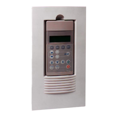
Figure 1-3 ACS 300 options.
Other manuals for ACS 300
1
This manual suits for next models
32
Table of contents
Other ABB Media Converter manuals

ABB
ABB ACS580-01 drives Installation manual
ABB
ABB ACS150 series Installation manual

ABB
ABB ACS800-67 User guide

ABB
ABB ACS880-1607LC User manual

ABB
ABB ACS880-1604 User manual

ABB
ABB MAG-SM Training manual

ABB
ABB ACH580-01 Series Installation manual

ABB
ABB SureWave SFC User manual

ABB
ABB ACS880-1607 User manual

ABB
ABB DCS 500B Operating and installation instructions