ABB EDS500 Series User manual

Operating instruction
Managed Ethernet switch 500NMD44
EDS500 series - Ethernet & DSL switches
Operating instruction
Managed Ethernet switch 500NMD44
EDS500 series - Ethernet & DSL switches
Application, characteristics and technical data have to
be taken from the hardware data sheet:
500NMD44 Data sheet 1KGT150996
Operation
The compact modem 500NMD44 has two optical
interface as SFP plug-in and four Ethernet interfaces.
There are two serial interfaces for configuration or
process interface (e.g. to connect telecontrol units). A
configurable alarm relais and an extension interface
(e.g. to use the configuration stick) complete the
device.
Console0
Tunnel CFG
local LAN
345 6
2
RS-232
Tunnel
Console1
CFG
1
WANWAN
RS-232/
RS-485
Configuration
and Monitoring
Intelligent Switch
(Layer 2 or 3)
Figure 1: 500NMD44 Blockschaltbild
Connections
Ethernet interfaces (Port1 - Port4)
Every Ethernet interface detects automatically
whether the connected counterpart works as
transmission or network termination device. This way
both normal and crossover cables can be used (MDI/
MDI-X).
The Ethernet interface can operate at transmission
rates of 10 or 100 Mbps, depending on the connected
devices in half duplex or full duplex mode. The
operation mode is detected and set automatically
by the EDS500 devices. A manual configuration is
possible.
Pin allocation Ethernet interface (RJ-45)
Pin assigned as data
transmission
device (MDI)
assigned as
network termi-
nation device
(MDI-X)
1 Tx+ Rx+
2 Tx- Rx-
3 Rx+ Tx+
4 n.c. n.c.
5 n.c. n.c.
6 Rx- Tx-
7 n.c. n.c.
8 1
8 n.c. n.c.
SFP Interfaces (Fo1 - Fo2)
All SFP interfaces are designed according to Small
Form-Factor Pluggable (INF-8074i).
WARNING
Only transceivers up to laser class 1 according to
EN 60825-1 are allowed to be used for the SFP
interfaces.
ADVICE
Any warranty claims can only extend to SFPs
delivered by ABB.
Serial interfaces (Con0 - Con1)
The serial interfaces of the device are signal
compatible to RS-232. The connector is an RJ-12
modular jack. The factory presets are speed 57600
Baud, no parity, 1 stop bit, no flow control. Via the
serial interfaces the management console can be
accessed .

Pin allocation serial interface RS-232 (RJ-12)
RS-232 RS-232 PC SUB-D9
Pin Signal Direction Pin Signal Direction
1 DCD Output 1 DCD Input
2 CTS Output 8 CTS Input
3 RTS Input 7 RTS Output
4 GND - 5 GND -
5 RxD Output 2 RxD Input
61
6 TxD Input 3 TxD Output
Pin allocation serial interface RS-485 half duplex
(RJ-12)
RS-485 half duplex / 2-wire
Pin Signal Direction
1
2
3 B (-) bi-directional
4 GND -
5
61
6 A (+) bi-directional
Pin allocation serial interface RS-485 full duplex
(RJ-12)
RS-485 full duplex / 4-wire
Pin Signal Direction
1
2 B (-) Input
3 B (-) Output
4 GND -
5 A (+) Input
61
6 A (+) Output
Power connector (X1 and X3)
The EDS500 devices are equipped with a wide range
power supply for voltages between 24 and 60 Volts DC
(power consumption see device label). The connector
is a 4-pin Phoenix plug with screw terminals.
Devices supporting Power over Ethernet (PoE) do have
an additional 4-pin Phoenix power plug. The input
voltage depends on the Rubrik of the device.
Pin allocation power supply (X1)
Pin Signal
1 24-60 V DC
2 Shield connected to functional earth
(internally wired to pin 4)
3 GND
1 2 3 4
4 Shield connected to functional earth
(internally wired to pin 2)
Pin allocation power supply PoE (X3)
Pin Signal
1 R0001: 51-57 V DC
R0002: 24-60 V DC
2 Shield connected to functional earth
(internally wired to pin 4)
3 GND
1 2 3 4
4 Shield connected to functional earth
(internally wired to pin 2)
ADVICE
Due to the internal overvoltage protection,
interrupt any connection to ground of the device
for the time of the measurement before you carry
out isolation measurements. This includes the
earthing of the hat rail as well as all shields of all
transmission lines and supply feedings. RJ-12 plugs
or RJ-45 plugs can also establish earthing via the
shield.
Extension interface (EXT)
The plug of the proprietary expansion bus is designed
as USB type B but uses a manufacturer specific
protocol.
The configuration parameters are stored directly
on the device. In addition, a configuration stick can
be connected to the expansion bus to save data
externally, in example to exchange defective devices
easily.
ADVICE
Danger of damaging the device
Do not connect any USB devices!
Alarm relay (X2)
The EDS500 devices are equipped with a potential free
alarm output (relay with isolated switchover contact).
This output corresponds to a device alarm and is
activated when the device looses the power supply
or the alarm LED is constantly on. The reason for the
signaling of an alarm can be referenced in the system
alarm table (EDS500 Manual - Part 2: Alarms and alarm
configuration).
Pin allocation alarm output (X2)
Pin Signal
1 & 2 Normal state
1 & 3 Alarm state
1 2 3 4
4 Common contact (connected to 1)
WARNING
The relay is designed for switching only safety extra
low voltages.

Signaling
LED Description Function
off Device is without
power supply
Power Voltage
Supply
green Power supply
switched on
off Hardware fault or
booting
Ready Ready
green Device ready
off SFP not pluggedFo1: Module
Fo2: Module
SFP Module
plugged green SFP plugged
off no optical link
active
Fo1: Link
Fo2: Link
SFP link
active
green Optical link estab-
lished
off No activity on the
optical interface
Fo1: Activity
Fo2: Activity
SFP activity
green Data is trans-
mitted via the
optical interface
off DCD inactive on
Con interface
Con0: DCD
Con1: DCD
Con DCD
active
green DCD active
off No activity on the
Con interface
Con0:
Activity
Con1:
Activity
Con activity
green Data is trans-
mitted via Con
off No alarm
flash Warning or
configuration
error
Alarm Alarm
red Alarm
off No alarmFo Alarm SFP Alarm
red Alarm about the
SFP interface(s)
off No connection
green Link established
Port 1-4: L Ethernet
connection
flash Activity (send or
receive)
off Data rate 10 MbpsPort 1-4: S Ethernet
data rate orange Data rate 100
Mbps
off port not
configured for
PoE
Port 1-4: PoE
En
Power over
Ethernet
enabled
green port configured
for PoE
off no PoE device
connected
Port 1-4: PoE
Act
Power over
Ethernet
active green PoE device active
supplied
Overall
Power
Allocation
0% to
100%
Total sum of
power requested
by connected PoE
devices
During start-up all displays light up shortly for about
1 second. As soon as the start-up has been finalized
successfully (about 30 seconds after switching on the
device) the LED "Ready" switches to green.
Device configuration
The 500NMD44 can be configured locally as well as
from remote. In the following some methods are
introduced, for a complete description please see
EDS500 Manual - Part 2: Functions (1KGT151021).
Configuration using a serial configuration cable
In delivery status all serial interfaces are in
configuration mode to provide access to the command
line. Using a serial configuration cable (500CAB06
1KGT038912R0001), the device can be connected to a
serial port of a PC/notebook.
The default configuration for the serial connection is:
57600 Baud 8N1 (8 data bits, no parity, 1 stop bit), no
hardware flow control.
IP based configuration, remote configuration
After establishing a network connection to the
device and configuring IP addresses as required (i.e.
“the device can be pinged”), the following remote
configuration features can be used:
•Telnet
Telnet clients like HyperTerminal, PuTTY or
telnet.exe (on the PC command line interface)
can be used to establish a telnet session with the
device. The IP address of the unit has to be used
as Telnet target. Telnet access can be disabled by a
configuration command.
•SSH
Suitable SSH clients on the PC side are programs
like Tera Term or PuTTY. The tar-get address is the
device’s IP address. During the connection you will
be prompted for authentication credentials. The
default login name is edslogin, the password is
empty when in delivery status. SSH access can be
disabled by configuration.
•Webserver
With the webserver activated (default setting)
browsers like Firefox, Opera, Safari, Chrome or
the Internet Explorer can be used to configure
the devices using the web interface. To do so
enter the device IP into the browser address
field. The device will subsequently request
authentication credentials. The default login name
is edslogin, the password is empty when in delivery
status. Webserver access can be disabled by a
configuration command.
The command line interface
The command line of the 500NMD44 is similar to the
(DOS) command line known from the PC. All device
properties can be set and shown here.
•Commands are typed into the console, pressing
<{Enter}> will start execution.
•Commands can be abbreviated as soon as they
are unambiguous, i.e. <sh sy> is equivalent
to <show system>, <se sw p1 n s>
is equivalent to <set switch port1 no
shutdown>.
•A command overview can be listed on every level by
typing <?>. Example: <sh sy ?> translates to
<show system ?> and results in snmp sntp
ssh syslog temperature being shown
as command keywords to follow, i.e. one possible
command is <show system temperature>.

•There are two authentication levels on the
command line: Login authentication and Enable
authentication. Login authentication can be
described as a read only mode and is accessible
directly after establishing a serial connection
with the PC. Enable authen-tication is required
once you need to change system settings or
show the complete system parameter set.
Enable authentication is reached by entering
the <enable> command. Both authentication
levels can be protected by a password, the
respective commands are <set loginpass
{string20}> and <set enablepass
{string20}>.
•Configuration commands entered on the
command line interface are stored in the running
configuration of the device, which represents the
current state of the system. To preserve this status
after a reboot, the running configuration must
be transferred to the startup configuration using
the command <write>. During system startup
all commands from the startup configuration
are being executed and thus create the running
configuration. When a configuration stick is
attached to the device, executing the <write>
command results in the running configuration
being copied not only to the startup configuration
but also to the stick configuration (unless the stick
is set to “read only”). During system startup with
attached config stick, the stick configuration over-
writes the startup configuration.
•The current configuration (running configuration)
can be displayed using the command <show
running-config> (only with Enable
authentication). The start configuration may be
shown using <show startup-config>.
When a config stick is attached, its content can be
shown using <show stick-config >.
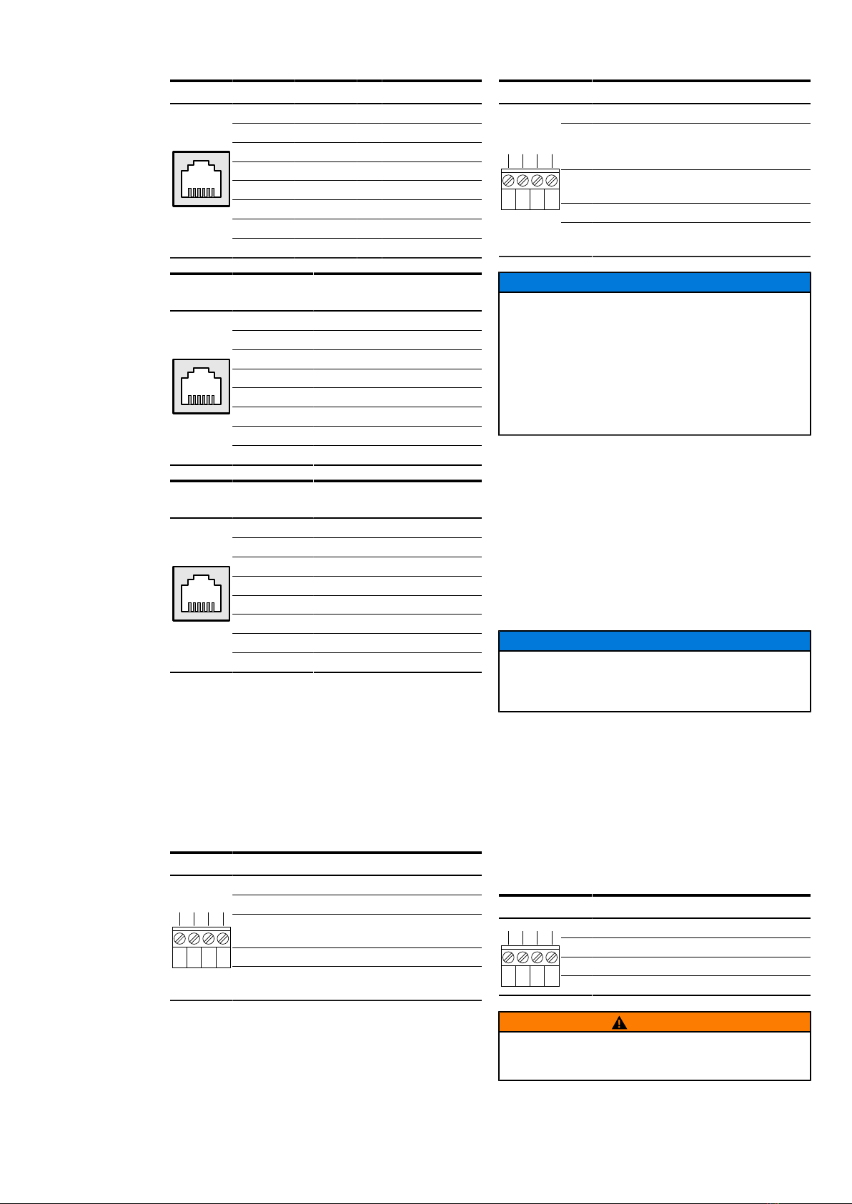
Interface configuration
Ethernet Interfaces
The Fast Ethernet interfaces (IEEE802.3 compliant,
10Base-T/100BaseTX) support auto MDIX, therefore
terminal devices and network equipment can be
connected both with regular and crossover cables.
Cable connection uses conventional 8P8C connectors
(RJ45). Auto negotiation as well as static speed and
duplex settings are supported. In delivery state all
interfaces are activated and auto negotiation is
con-figured. If you need to configure, for instance,
a 10 Mbps half duplex connection for port 2, the
following commands must be issued: <set switch
port2 duplex half>, <set switch port2
speed 10> and <set switch port2 no
shutdown>.
Optical Interfaces
The optical interfaces are realized as SFP module slots
(Small Formfactor Plugga-ble, INF-8074i) und can be
equipped with different transceivers. The speed is
fixed to 100 Mbps, the duplex setting can be changed
(full duplex, half duplex). Delivery configuration is 100
Mbps, full duplex.
ADVICE
When using a managed SFP unit, parameters of the
optical interface like signal quality or temperature
can be displayed and monitored.
VLAN configuration
The Ethernet, DSL and optical interfaces of the
EDS500 devices support virtual LANs complying
with the IEEE 802.1Q standard. Thus it is possible to
define logical sub-nets for different applications (for
instance, one subnet for RTU communication, an-
other subnet for voice-over-IP). The interfaces can be
configured as trunk or access ports. In default state
the DSL interfaces are configured as trunk.
Example:
•<set switch port1 access-vlan 10>
configures port 1 as access port for VLAN 10.
•<set switch port2 trunk-vlan 10>,
<set switch port2 trunk-vlan 20>
configures port 2 as trunk port for VLANs 10 and 20
(secure trunk).
•<set switch port3 trunk-vlan all>
configures port 3 as trunk for all VLANs.
System settings
Device IP Address
In delivery state the devices have following IP
configuration:
IP Address 10.0.0.2
IP Subnet Mask 255.0.0.0
IP Gateway 10.0.0.1
These parameters can be changed by commands listed
below:
<set system ip {IP address}>
<set system subnetmask {subnet
mask}>
<set system gateway {IP address}>
System Identification Settings
For an easier identification of the devices several
description parameters can be set:
•Hostname: <set system hostname
{name}>
•Contact: <set system contact
{contact}>
•Location: <set system location
{location}>
•Description: <set system description
{text}>
Device monitoring
For central processing of device syslog messages a
syslog server can be configured with the following
command:
<set system syslog server {IP
address} {{0-7} | abb-security-
events}>
In order to provide “real” timestamps in the event log
and the syslog messages a SNTP time server can be
configured:

<set system sntp server {IP
address}>
<set system sntp timezone {cet |
cet-cest | eet | gmt}>
Specifying a SNMP trap server:
<set system snmp trap-target
{IP address} [{v1|v2c}]
[{community}]>
Firmware Update
The firmware is updated by transferring a firmware
image to the device. It can be downloaded with
the help of the command line (Telnet, SSH, serial
terminal) as well as with the help of the integrated
web interface, scripts or a management program. It is
mandatory that there is an IP connection to the device.
ADVICE
During a firmware update the power supply
must not be interrupted or a reboot must not
be triggered as this could leave the device in an
inoperable state.
Reset button
Pressing the reset button restarts the device and
loads the saved configuration (startup-config or stick-
config). As a protection against accidental triggering,
the reset button is in a concealed place and can be
reached with a pointed tool (e.g. paper clip).
ADVICE
If the running configuration (= running-config)
does not match the savedconfiguration (= startup-
config) it is lost with the restart.
ADVICE
All established communication connections will be
lost during restart.
Safety
DANGER
Interrupt the power supply before mounting or
dismounting the device.
WARNING
An easy to access manual interrupter has to be
installed into the power feed of the modem to be
able to disconnect the modem from the power
supply in the case of an emergency.
WARNING
The EDS500 devices are intended only for use
in restricted access area. For fire protection
the devices have to be mounted into suitable
cubicles which are certified for the function of a fire
protection housing.
WARNING
The DC power supply has to fulfil the following
requirements in order to supply appropriate fire
protection:
•Limited power source according to IEC 60950-1
or PS2 classified according to IEC 62368-1
•Short-circuit current < 8A
WARNING
The device shall be powered off while accessing
any of the connectors X1 (power connector)or X2
(alarm relay). Any other connectors (e.g. Ethernet,
RS-232, RS-485or DSL) are hot-pluggable while the
device is operating.
WARNING
No plug shall be freely accessible in normal
operation due to safety reasons.
WARNING
Only transceivers up to laser class 1 according to
EN 60825-1 are allowed to be used for the SFP
interfaces.

Figure 2: 500NMD44 Front plate
Figure 3: 500NMD44 R0001Label
Figure 4: 500NMD44 R0002Label

ABB Power Grids Germany AG
P.O. Box 10 01 64
68128 Mannheim, Germany
solutions.abb/eds500
We reserve the right to make technical
changes or modify the contents of this
document without prior notice. With
regard to purchase orders, the agreed
particulars shall prevail. ABB Power
Grids Germany AG does not accept any
responsibility whatsoever for potential
errors or possible lack of information in
this document.
We reserve all rights in this document and in
the subject matter and illustrations contained
therein. Any reproduction, disclosure to third
parties or utilization of its contents – in whole
or in parts – is forbidden without prior written
consent of ABB Power Grids Germany AG.
Copyright© 2020 ABB Power Grids Germany AG
All rights reserved
1KGT150997 V000 1
Other manuals for EDS500 Series
7
This manual suits for next models
1
Other ABB Switch manuals

ABB
ABB 3299A-A12100 Operation manual

ABB
ABB Sense 7 Series User manual

ABB
ABB Zenith ZTX Series User manual

ABB
ABB OTM3200E4230C-GE User guide

ABB
ABB OTM_C_21D User manual

ABB
ABB E-Hub 2.0 User manual

ABB
ABB Ekip CI User manual

ABB
ABB DTW User guide

ABB
ABB EDS500 Series User manual

ABB
ABB OTM3200E4M230C-GE User manual

ABB
ABB NE801 User manual

ABB
ABB ATS022 User manual

ABB
ABB NE820 User manual

ABB
ABB E 232 E-8/230N User manual

ABB
ABB InLine II ZHBM-ITS Series User manual

ABB
ABB IS/S 8.1.1 User manual

ABB
ABB Tmax User manual

ABB
ABB ABB-free@home LS-1.1 User manual

ABB
ABB vital 1 User manual

ABB
ABB EOHU Series Training manual