ABLE2 SecuCare PR30332 User manual

C= 100 ; M= 100
C= 100 ; M= 30
C= 100 ; Y= 100
C= 40 ; Y= 100
M= 10 ; Y= 100
M= 60 ; Y= 100
M= 100; Y= 100
M= 40; C= 20; Y=20; K=100
K= 90
K= 75
K= 50
K= 35
K= 25
K= 45
K= 70
SecuCare logo - denitieve versie 1.0 - 16 september 2010
v2- aanpassing: zwart in cmyk 40 20 20 100 - 7 november 2013
Drempelhulp - Set 3 Montagehandleiding
Threshold Ramp - Set 3 Assembly manual
Schwellenrampe - Set 3 Montageanleitung
Rampe de seuil - Set 3 Manuel de montage
Rampa - Serie 3 Istruzioni di montaggio
Rampa salvaescalón - Juego 3 Manual de montaje
Rampa para degrau de entrada - Conjunto 3 Manual de montagem

1
C= 100 ; M= 100
C= 100 ; M= 30
C= 100 ; Y= 100
C= 40 ; Y= 100
M= 10 ; Y= 100
M= 60 ; Y= 100
M= 100; Y= 100
M= 40; C= 20; Y=20; K=100
K= 90
K= 75
K= 50
K= 35
K= 25
K= 45
K= 70
SecuCare logo - denitieve versie 1.0 - 16 september 2010
v2- aanpassing: zwart in cmyk 40 20 20 100 - 7 november 2013
Drempelhulp - Set 3: Montagehandleiding
Threshold Ramp - Set 3: Assembly manual
Schwellenrampe - Set 3: Montageanleitung
Rampe de seuil - Set 3: Manuel de montage
Rampa - Serie 3: Istruzioni di montaggio
Rampa salvaescalón - Juego 3: Manual de montaje
Rampa para degrau de entrada - Conjunto 3: Manual de montagem
2 - 9
10 - 17
18 - 25
26 - 33
34 - 41
42 - 49
50 - 57

2
C= 100 ; M= 100
C= 100 ; M= 30
C= 100 ; Y= 100
C= 40 ; Y= 100
M= 10 ; Y= 100
M= 60 ; Y= 100
M= 100; Y= 100
M= 40; C= 20; Y=20; K=100
K= 90
K= 75
K= 50
K= 35
K= 25
K= 45
K= 70
SecuCare logo - denitieve versie 1.0 - 16 september 2010
v2- aanpassing: zwart in cmyk 40 20 20 100 - 7 november 2013
Drempelhulp - Set 3 Montagehandleiding
Benodigd gereedschap: Meegeleverd montagemateriaal:
Eventueel aangevuld met een (schroef)
boormachine.
Bevestigingsmateriaal, 1 slagplaatje
en 3 laminaatvoeten.
45cm
4,5 - 6cm
84cm
of
of

3
onderdeel nummer aantal artikel nummer
Pastegel heel 4x3 nr. 13 3 8026.100.09
Pastegel half 2x3 nr. 14 1 8026.100.10
Connector 4x1 nr. 10 3 8026.100.11
Connector 2x1 nr. 11 1 8026.100.13
Connector 2x2 nr. 12 3 8026.100.12
Ramp heel nr. 5 6 8026.100.06
Ramp half nr. 7 2 8026.100.07
Tegel kwart nr. 6 1 8026.100.05
Tegel half nr. 3 3 8026.100.03
Vultegel half nr. 4 1 8026.100.04
Vultegel heel nr. 2 3 8026.100.02
Doos inhoud
Vuldop grijs 14 8025.010.02
Vuldop bruin 14 8025.010.03
Antislip doppen 14 8025.010.01
Optionele accessoires, niet in de doos

4
Montage drempelhulp
Lees de handleiding eerst goed door voordat u gaat monteren.
1Plaats het eerste deel van
laag 2 op laag 1.
4Bevestig alle delen van de
1e rij.
5Ga door met de 2e rij. 6Het eindresultaat van de
twee samengestelde lagen.
2Met een stevige klap van de hamer (altijd het slagplaatje
gebruiken) slaat u de eerste klikker vast. Houd daarbij de
aangegeven richting aan en de hamer in de juiste stand.
BIndien u de drempelhulp wil bevestigen op
steen dient u de drie meegeleverde grote ringen
te plaatsen op de onderste laag.
ALeg de kunststof onderdelen op een vlakke ondergrond.

5
CBepaal nu of u eventueel de hoogte moet aanpassen.
Bepaal of de pastegel aangepast moet worden om
de juiste hoogte te krijgen.
Bij gebruik volledige pastegel:
Volledige max. hoogte van de set.
Bij gebruik 2/3pastegel:
Volledige hoogte minus 5mm.
Bij gebruik 1/3pastegel:
Volledige hoogte minus 10mm.
Verwijder de halve pastegel met de meegeleverde connector schuin en kort alle pastegels in op de juiste
maat.
Plaats de halve pastegel dwars op een tegeldeel. Met een stevige klap van de hamer (gebruik altijd het
slagplaatje) slaat u deze vast. Bepaal waar u, aan de hand van de best passende hoogte, de pastegel
eventueel dient in te korten. In de tegel zijn daarvoor aanwezige snijlijnen aangebracht.

6
1Bepaal de montage gaten en teken af.
3Bevestig nu de drempelhulp m.b.v. van de
meegeleverde lange schroeven aan de ondergrond. 4Plaats als laatste de (eventueel) op maat
gemaakte pastegels.
2Boor (steen 6 mm) en plaats de pluggen.
Bevestiging op steen
Indien u de drempelhulp wil bevestigen op steen/hout dient u eerst alle connectoren aan te brengen:
Plaats de connectoren vierkant & langwerpig zoals op onderstaande afbeelding. U kunt deze
connectoren met de hand erop drukken maar ook door het zwarte kunststof slagplaatje te plaatsen
op de connector klikverbinding en deze vast te tikken met een hamer. Zorg voor een stevige vlakke
ondergrond. In combinatie met de (rubber)hamer dient u altijd het slagplaatje te gebruiken.
6Ga door tot alle pastegels bevestigd zijn.5Met een stevige klap van de hamer op het
slagplaatje, slaat u de eerste klikker vast.
Slaan in de richting zoals aangegeven op
onderstaande afbeelding.
Zie afb. Bvoor plaatsing ringen

7
Bevestiging op een gladde ondervloer
Stel de drempelhulp samen zoals in de eerder beschreven stappen:
Het bevestigen van de drempelhulp op een gladde ondervloer (zoals bijvoorbeeld laminaat, of
gladde tegels) kan met de meegeleverde vlakke klikvoeten. Plaats de klikvoeten en voorzie ze van de
meegeleverde dubbelzijdige tape. Verwijder de schutlaag.
Tip: voor bevestiging op een niet gladde stenen ondervloer kunt u eventueel de klikvoeten vastzetten met
de meegeleverde schroeven en pluggen.
Reinig / ontvet de ondergrond grondig. Plaats nu de SecuCare drempelhulp op de juiste plek, stevig
aandrukken.

8
Tip: Het SecuCare drempelhulp systeem is eventueel demonteerbaar. U kunt de lagen los halen van elkaar
door gebruik te maken van de aanwezige schuine connector. Doe dit met beleid, gebruik geen ander soort
gereedschap, daarmee kunt u de drempelhulp beschadigen.
Bevestiging aan een opstaande verhoging of drempel
Bepaal waar de 3 (korte) bevestigings schroeven moeten komen en snij de voorbereide uitsparingen uit.
Bepaal aan de hand van de
gemaakte uitsparingen waar de
schroeven te plaatsen, hoogte
vanaf de vloer 10mm.
Teken af op de opstaande rand/
drempel, boor voor en bevestig
de schroef en ring. Draai de
schroef niet helemaal vast, de
uitsparingen moeten tussen de
rand/drempel en de ring passen.
Plaats nu de drempelhulp over de schroef/ring.

9
Belangrijk
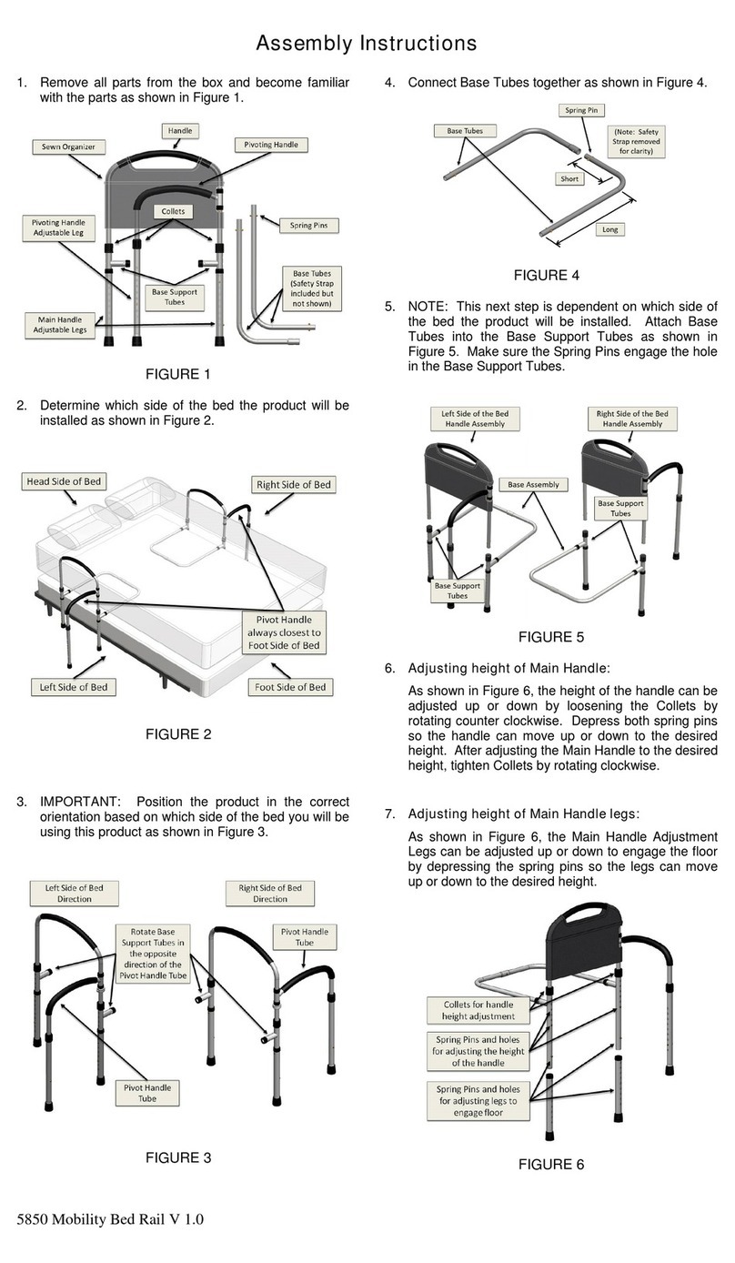
• Lees zorgvuldig de montage instructie en disclaimer door.
• Zorg voor een stevige en vlakke ondergrond.
• Pas op voor uitglijden in bepaalde weersomstandigheden.
Strooi zout in geval van ijzel of gebruik het systeem dan niet.
• Zorg ervoor dat dit systeem geen gevaar/hinder veroorzaakt
(bijv. in een woning galerij).
• De omgeving dient voldoende verlicht te zijn zodat
het systeem goed zichtbaar is, speciaal in een publieke
omgeving en voor mensen met een zichtbeperking
Algemene bepalingen
• Plaatsing en gebruik van de drempelhulp geschiedt op eigen
risico.
• De drempelhulp is uitsluitend ontworpen voor, en geschikt
voor, gebruik door personen van gemiddeld gewicht te voet,
met een rollator of in een rolstoel , en derhalve voor geen
enkele andere toepassing.
• De ondergrond waarop de drempelhulp wordt gemonteerd,
dient vlak en stabiel en solide te zijn.
• Het systeem nooit gebruiken in de buurt van, of in combinatie
met, ontvlambare materialen. Het systeem is in dat geval ook
niet geschikt voor vlucht routes.
• De hellingshoek van de drempelhulp dient zo klein mogelijk
te zijn. Indien de situatie ter plekke dwingt tot een steile hoek,
dient de gebruiker(s) gedurig hulp geboden te worden bij
gebruik van de drempelhulp.
• Indien verzagen van de drempelhulp plaatsheeft, dienen
voldoende beschermende middelen (veiligheidsbril,
oorbeschermers e.d.) te worden gedragen.
• Kleine onderdelen van de drempelhulp dienen buiten het
bereik van kinderen te worden gehouden, om inslikken etc. te
voorkomen.
• Bij gebruik van naaldhakken wordt dringend aanbevolen het
systeem uit te rusten met los leverbare anti slip doppen (art.
nr 8025.010.01, 14 stuks). Hierdoor ontstaat een vlak geheel
(n.v.t. bij set 1).
• Na montage en daarna van tijd tot tijd, dient te worden
gecontroleerd of de drempelhulp in de situatie ter plekke
stevig genoeg is voor normaal gebruik.
• De omgeving van het drempelsysteeem dient gedurig
voldoende verlicht te zijn, waardoor de drempelhulp goed
zichtbaar is voor anderen, voor wie de drempelhulp immers
een obstakel kan zijn; voor gebruik van de drempelhulp op
galerijen is een drempelsysteem verkrijgbaar met schuine
zijkant.
• Afhankelijk van de hoogte van het systeem is een geleide-rail
(die ongelukken voorkomt) aan weerszijden van het systeem
aan te raden/verplicht. Controleer uw lokale wetgeving hierop
of neem contact op met uw leverancier of Secu voor meer
informatie.
• Lokale regels voor het kenbaar maken van de drempelhulp
dienen te worden nagekomen. In geval van gladheid van de
drempelhulp, bijvoorbeeld door weersomstandigheden doch
niet beperkt daartoe, dienen passende maatregelen tegen
uitglijden door die gladheid genomen te worden waarbij
bijvoorbeeld de drempelhulp tijdelijk kan worden verwijderd.
• Bij twijfel door de consument over enig aspect van montage
of gebruik van de drempelhulp dient onverwijld contact op te
worden genomen met de leverancier van de drempelhulp, van
wie de consument dat heeft betrokken.
Onderhoud
• Van tijd tot tijd dient de stevigheid van de drempelhulp en van
de onderlinge verbindingen te worden gecontroleerd.
• De drempelhulp en de ondergrond dient gedurig schoon
te worden gehouden. Elke soort schoonmaakmiddel en
zelfs een autoclaaf kan gebruikt worden ter reiniging van de
drempelhulp.
• Eventueel grof vuil kan worden verwijderd met een borstel en
daarna dient de drempelhulp afgespoeld te worden met water.
Garantie
Voor inroeping van garantie op de drempelhulp is overlegging
van het bewijs van aankoop van de drempelhulp voorzien van
aankoopdatum en productomschrijving of productnaam, vereist.
Garantie wordt gegeven voor de duur van vijf jaar gerekend
vanaf de datum van aankoop van de drempelhulp door de
consument. De garantie geldt uitsluitend aangaande eventuele
productiefouten van de in de drempelhulp gebruikte materialen.
Een terecht beroep op garantie leidt uitsluitend tot een
aanspraak op kostenloze levering door Secu aan de consument
van een vervangend drempelsysteem; Secu is niet gehouden
tot enige andere prestatie. Secu accepteert geen enkele
aansprakelijkheid voor enige letselschade of enige zaakschade
of enige gevolgschade die ontstaat tijdens montage van de
drempelhulp en/of tijdens gebruik van de drempelhulp; enige
aansprakelijkheid welke desondanks voor rekening van Secu
komt, is beperkt tot het bedrag dat in het bewuste geval wordt
uitgekeerd door Secu’s aansprakelijkheidsverzekeraar.
De garantie vervalt met onmiddellijke ingang door:
• Montage die niet conform is aan de bij de drempelhulp
geleverde montageinstructie resp. geschiedt met ander dan
het meegeleverde montagemateriaal;
• Verkeerd, oneigenlijk of te zwaar belastend gebruik (max.
belasting 850 kg/m2) van de drempelhulp;
• Opzettelijke of door verwaarlozing van de drempelhulp
ontstane beschadigingen;
• Bij toepassing van de drempelhulp op een oneffen en/of
instabiele en/of onvoldoende solide ondergrond;
• Beschadigingen veroorzaakt door gebrek aan onderhoud,
door verkeerd onderhoud of door gebruik van verkeerde
reinigingsmiddelen (zie reinigingsadvies);
• Invloed van chemische/elektrochemische stoffen en/of invloed
van elektriciteit;
Wijzigingen voorbehouden
SecuCare is een merk van SECUPRODUCTS BV
Luzernestraat 29 - 2153 GM Nieuw-Vennep - NL
Disclaimer en garantie voorwaarden - SecuCare drempelhulp
Versie 3.0 januari 2016
10
C= 100 ; M= 100
C= 100 ; M= 30
C= 100 ; Y= 100
C= 40 ; Y= 100
M= 10 ; Y= 100
M= 60 ; Y= 100
M= 100; Y= 100
M= 40; C= 20; Y=20; K=100
K= 90
K= 75
K= 50
K= 35
K= 25
K= 45
K= 70
SecuCare logo - denitieve versie 1.0 - 16 september 2010
v2- aanpassing: zwart in cmyk 40 20 20 100 - 7 november 2013
Threshold Ramp – Set 3 Assembly manual
Required tools: Mounting materials supplied:
Possibly supplemented by a (screw) drill.
Fastening materials, 1 strike plate
and 3 laminate feet.
45cm
4,5 - 6cm
84cm
or
or

11
part number quantity article number
Fitting plate, whole
4x3
no. 13 3 8026.100.09
Fitting plate, half
2x3
no. 14 1 8026.100.10
Connector 4x1 no. 10 3 8026.100.11
Connector 2x1 no. 11 1 8026.100.13
Connector 2x2 no. 12 3 8026.100.12
Ramp, whole no. 5 6 8026.100.06
Ramp, half no. 7 2 8026.100.07
Tile, quarter no. 6 1 8026.100.05
Tile, half no. 3 3 8026.100.03
Filling plate, half no. 4 1 8026.100.04
Filling plate, whole no. 2 3 8026.100.02
Box contents
Filler cap, grey 14 8025.010.02
Filler cap, brown 14 8025.010.03
Anti-skid caps 14 8025.010.01
Optional accessories, not in the box

12
Assembly of Threshold Ramp
Carefully read the manual before starting the assembly.
1Place the first part of layer 2
onto layer 1.
4Attach all the parts of the 1st
row.
5Continue with the 2nd row. 6The end result of the
two assembled layers.
2You can attach the first click connector with a firm tap of the
hammer (always use the strike plate). Use the indicated direction
and hold the hammer in the right position.
BIf you want to attach the Threshold Ramp to
stone, you must place the three supplied large
washers on the bottom layer.
APlace the plastic parts on a flat surface.

13
CNow determine if you will have to adjust the height.
Determine if the fitting plate will have to be
modified to achieve the correct height.
Remove the half-size fitting plate using the supplied sloping connector and cut all fitting plates to the
correct size.
Rotate the half-size fitting plate 90 degrees and place it onto a plate part. Attach it with a firm tap of the
hammer (always use the strike plate). Determine where you may have to shorten the fitting plate based
on the best fitting height. Cutting lines are present on the plate for this.
When using a full fitting plate: full
max. height of the set.
When using 2/3of the fitting
plate: full height minus 5mm.
When using 1/3of the fitting
plate: full height minus 10mm.

14
3Now attach the Threshold Ramp to the surface
using the supplied long screws. 4Finally, place the fitting plates that were
(possibly) cut to size.
2Drill (stone 6 mm) and place the plugs.
Attaching to stone
If you want to attach the Threshold Ramp to stone/wood, you must first attach all the connectors: Place
the connectors, square & rectangular, as depicted in the picture below. You can push these connectors
in place with your hand, but you can also place the black plastic strike plate on the connector click
connection and tap it in place with a hammer. Make sure the surface underneath is solid and flat. In
combination with the (rubber) hammer, you must always use the strike plate.
6Continue until all the fitting plates have been
attached.
5You can attach the first click connector with a
firm tap of the hammer on the strike plate. Tap in
the direction indicated in the picture below.
See fig. Bfor washer placement
1Determine the mounting holes and mark
them out.

15
Attaching to a slippery surface
Assemble the Threshold Ramp as described in the previous steps:
The Threshold Ramp can be attached to a slippery surface (e.g. laminate or slippery tiles) using the
supplied flat click feet. Place the click feet and attach the supplied double-sided tape to them. Remove
the release liner.
Tip: when attaching the aid to a non-slippery stone surface, you can also secure the click feet using the
supplied screw and plugs.
Thoroughly clean / degrease the surface. Now place the SecuCare Threshold Ramp in the right location,
push it down firmly.

16
Tip: The SecuCare Threshold Ramp system can be disassembled if required. You can detach the layers by
using the sloping connector provided. Do this carefully and do not use any other kinds of tools, as you may
damage the Threshold Ramp with those.
Attaching to a raised edge or doorstep
Determine where the 3 (short) fastening screws will have to go and cut out the prepared openings.
Use the openings made to
determine where the screws are
to be mounted, height 10mm
from the floor.
Mark the location on the raised
edge/doorstep, pre-drill and
fasten the screw and washer. Do
not fully tighten the screw; the
openings must fit between the
edge/doorstep and the washer.
Now place the Threshold Ramp over the screw/washer.

17
Important
• Carefully read the assembly instructions and disclaimer.
• Make sure the surface underneath is solid and flat.
• Be careful not to slip in certain weather conditions. Grit the
area in case of freezing rain or do not use the system under
such circumstances.
• Make sure that this system does not cause any danger/
hindrance (e.g. in a communal walkway).
• The surrounding area must be sufficiently illuminated to
ensure that the system is clearly visible, especially in a public
place and for people with a visual disability
General provisions
• The Threshold Ramp is installed and used at your own risk.
• The Threshold Ramp is only designed for and suitable for use
by persons of an average weight on foot, with a rollator or in a
wheelchair, and therefore not for any other application.
• The surface on which the Threshold Ramp is mounted must be
flat, stable and solid.
• Never use the system in the vicinity of or in combination with
flammable materials. In that case, the system is not suitable for
escape routes either.
• The angle of the Threshold Ramp must be as low as possible. If
the local situation requires a steep angle, the user(s) must be
constantly assisted when using the Threshold Ramp.
• When cutting the Threshold Ramp, adequate protective
equipment (safety glasses, ear protection, etc.) must be worn.
• Small parts of the Threshold Ramp must be kept out of reach
of children to prevent swallowing, etc.
• When using high heels, it is highly recommended to fit
separately available anti-skid caps to the system (art. no.
8025.010.01, 14 pcs). This creates a flat surface (not applicable
to set 1).
• After assembly and from time to time afterwards, the
Threshold Ramp must be checked to see if it is sturdy enough
for normal use in the local situation.
• The area around the doorstep system must be sufficiently
illuminated all the time, making the Threshold Ramp clearly
visible to others, for whom the Threshold Ramp can be an
obstacle after all; for use of the Threshold Ramp in communal
walkways, a doorstep system with a sloping side is available.
• Depending on the height of the system, having guide
rails (preventing accidents) on both sides of the system is
recommended/mandatory. Check your local legislation for this
or contact your supplier or Secu for more information.
• Local rules for identifying the Threshold Ramp must be
observed. If the Threshold Ramp is slippery, e.g. due to
weather conditions, but not limited to this, suitable measures
against slipping due to this slipperiness must be taken,
whereby the Threshold Ramp can be temporarily removed, for
example.
• When in doubt about any aspect of the assembly or use of the
Threshold Ramp, the consumer should immediately contact
the supplier of the Threshold Ramp from which the consumer
purchased it.
Maintenance
• From time to time, the sturdiness of the Threshold Ramp and
the individual connections must be checked.
• The Threshold Ramp and the surface underneath must be
kept clean at all times. Any type of cleaning product, even an
autoclave, can be used to clean the Threshold Ramp.
• Any coarse dirt can be removed with a brush, after which the
Threshold Ramp must be rinsed with water.
Warranty
Any warranty claims on the Threshold Ramp require proof
of purchase of the Threshold Ramp to be produced, stating
the purchase date and product description or product name.
Warranty is provided for a period of five years, starting on the
date on which the consumer purchased the Threshold Ramp. The
warranty only applies to any production errors of the materials
used in the Threshold Ramp. A well-founded warranty claim shall
only result in the consumer being eligible for Secu supplying a
replacement doorstep system free of charge; Secu is not obliged
to provide anything else. Secu does not accept any liability
whatsoever for any personal injury or any material damage
or any consequential loss that occurs during assembly of the
Threshold Ramp and/or during use of the Threshold Ramp; any
liability to which Secu may be subject despite this is limited to
the amount paid by Secu’s liability insurer in the relevant case.
The warranty expires immediately if:
• assembly does not meet the assembly instructions supplied
with the Threshold Ramp or is performed with materials other
than the supplied mounting materials;
• the Threshold Ramp is used incorrectly, improperly or with
excessive loads (max. load 850 kg/m2);
• damage is caused to the Threshold Ramp deliberately or
through neglect;
• the Threshold Ramp is used on an uneven and/or unstable
and/or insufficiently solid surface;
• any damage is caused by a lack of maintenance, by incorrect
maintenance or by using the wrong cleaning products (see
cleaning recommendation);
• effects of chemical/electrochemical substances and/or effects
of electricity occur.
Subject to change
SecuCare is a trademark of SECUPRODUCTS BV
Luzernestraat 29 - 2153 GM Nieuw-Vennep - NL
Disclaimer and warranty conditions – SecuCare Threshold Ramp
Version 3.0 January 2016

18
C= 100 ; M= 100
C= 100 ; M= 30
C= 100 ; Y= 100
C= 40 ; Y= 100
M= 10 ; Y= 100
M= 60 ; Y= 100
M= 100; Y= 100
M= 40; C= 20; Y=20; K=100
K= 90
K= 75
K= 50
K= 35
K= 25
K= 45
K= 70
SecuCare logo - denitieve versie 1.0 - 16 september 2010
v2- aanpassing: zwart in cmyk 40 20 20 100 - 7 november 2013
Schwellenrampe - Set 3 Montageanleitung
45cm
4,5 - 6cm
84cm
oder
oder
Benötigtes Werkzeug:
Eventuell zusätzlich eine (Schraub-)
Bohrmaschine.
Mitgeliefertes Befestigungsmaterial:
Befestigungsmaterial, 1 Schlagplatte
und 3 Laminatstutzen.

19
Zubehörteil Nummer Anzahl Artikel nummer
Aufsatzstück
komplett 4x3
no. 13 3 8026.100.09
Aufsatzstück
halb 2x3
no. 14 1 8026.100.10
Verbindungsstück
4x1
no. 10 3 8026.100.11
Verbindungsstück
2x1
no. 11 1 8026.100.13
Verbindungsstück
2x2
no. 12 3 8026.100.12
Schwelle komplett no. 5 6 8026.100.06
Schwelle halb no. 7 2 8026.100.07
Schwellenstück
viertel
no. 6 1 8026.100.05
Schwellenstück halb no. 3 3 8026.100.03
Ergänzungsstück
halb
no. 4 1 8026.100.04
Ergänzungsstück
komplett
no. 2 3 8026.100.02
Inhalt der Verpackung
Abdeckkappen grau 14 8025.010.02
Abdeckkappen braun 14 8025.010.03
Antirutsch- Kappen 14 8025.010.01
Optionales Zubehör, nicht in der Verpackung enthalten
This manual suits for next models
1
Table of contents
Languages:
Other ABLE2 Mobility Aid manuals

ABLE2
ABLE2 PR60227 User manual

ABLE2
ABLE2 Deluxe PR30180-SL User manual

ABLE2
ABLE2 Atlantis PR46043 User manual

ABLE2
ABLE2 PR15341 User manual

ABLE2
ABLE2 PR30195 User manual

ABLE2
ABLE2 PR30107F-ICE User manual

ABLE2
ABLE2 PR15341 User manual

ABLE2
ABLE2 Atlantis PR45422 User manual

ABLE2
ABLE2 Saturn User manual

ABLE2
ABLE2 Neptune User manual
Popular Mobility Aid manuals by other brands

Drive DeVilbiss Healthcare
Drive DeVilbiss Healthcare MIGO 2G Instructions for use

Hewi
Hewi 802.51.11092 Installation and operating instructions

Allegion
Allegion NORMBAU 457 Series installation instructions

Arjo
Arjo MLA4060 Instructions for use

Handicare
Handicare SystemRoMedic QuickMove user manual

Nova
Nova TKW-12 user guide