manuals.online logo
Brands
  1. Home
  2. •
  3. Brands
  4. •
  5. Assa Abloy
  6. •
  7. Door Opening System
  8. •
  9. Assa Abloy King 70 Series User manual

Assa Abloy King 70 Series User manual

This manual suits for next models

29

Other Assa Abloy Door Opening System manuals

Assa Abloy Corbin Russwin DC3210 Series User manual

Assa Abloy

Assa Abloy Corbin Russwin DC3210 Series User manual

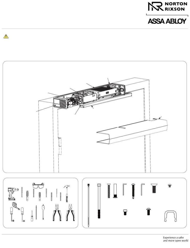
Assa Abloy Norton 6000 Series Installation manual

Assa Abloy

Assa Abloy Norton 6000 Series Installation manual

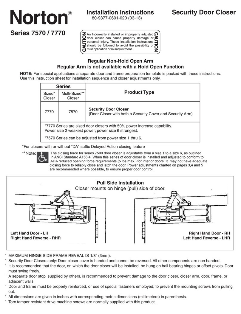
Assa Abloy Norton 7570 Series User manual

Assa Abloy

Assa Abloy Norton 7570 Series User manual

Assa Abloy King 640 User manual

Assa Abloy

Assa Abloy King 640 User manual

Assa Abloy Sargent PE8800 Series User manual

Assa Abloy

Assa Abloy Sargent PE8800 Series User manual

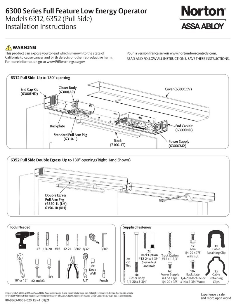
Assa Abloy NORTON RIXSON 6300 Series User manual

Assa Abloy

Assa Abloy NORTON RIXSON 6300 Series User manual

Assa Abloy G-CO-CS User manual

Assa Abloy

Assa Abloy G-CO-CS User manual
Assa Abloy Norton Narrow Profile Series User manual

Assa Abloy

Assa Abloy Norton Narrow Profile Series User manual

Assa Abloy RIXSON W91DCP User manual

Assa Abloy

Assa Abloy RIXSON W91DCP User manual

Assa Abloy Norton 5700P Series User manual

Assa Abloy

Assa Abloy Norton 5700P Series User manual

Assa Abloy Corbin Russwin ED4000 Series User manual

Assa Abloy

Assa Abloy Corbin Russwin ED4000 Series User manual

Assa Abloy Norton 5700 Series User manual

Assa Abloy

Assa Abloy Norton 5700 Series User manual

Assa Abloy Corbin Russwin DC6200 Series User manual

Assa Abloy

Assa Abloy Corbin Russwin DC6200 Series User manual

Assa Abloy G-CO-CS User manual

Assa Abloy

Assa Abloy G-CO-CS User manual

Assa Abloy Corbin Russwin ED5600 Series User manual

Assa Abloy

Assa Abloy Corbin Russwin ED5600 Series User manual

Assa Abloy Rixson Smok-Chek VI Quick guide

Assa Abloy

Assa Abloy Rixson Smok-Chek VI Quick guide

Assa Abloy Corbin Russwin PED5400 FE User manual
Assa Abloy

Assa Abloy Corbin Russwin PED5400 FE User manual
Assa Abloy Yale YM Series User manual

Assa Abloy

Assa Abloy Yale YM Series User manual

Assa Abloy Norton 8000 Series User manual

Assa Abloy

Assa Abloy Norton 8000 Series User manual

Assa Abloy DC340 User manual

Assa Abloy

Assa Abloy DC340 User manual

Assa Abloy SARGENT FIREGUARD 2499 User manual

Assa Abloy

Assa Abloy SARGENT FIREGUARD 2499 User manual

Assa Abloy SW200 Manual

Assa Abloy

Assa Abloy SW200 Manual

Assa Abloy Norton 7200 Series Quick guide

Assa Abloy

Assa Abloy Norton 7200 Series Quick guide

Assa Abloy Lockwood 5831 Series User manual

Assa Abloy

Assa Abloy Lockwood 5831 Series User manual

Popular Door Opening System manuals by other brands

Mobeye Call-Key MCK100 installation manual

Mobeye

Mobeye Call-Key MCK100 installation manual

SALICE Lapis Assembly instructions

SALICE

SALICE Lapis Assembly instructions

Cal-Royal N-F77CVR Installation instruction

Cal-Royal

Cal-Royal N-F77CVR Installation instruction

Scrigno OPEN1000 Assembly manual

Scrigno

Scrigno OPEN1000 Assembly manual

BFT WIND RMB 130B 200 installation manual

BFT

BFT WIND RMB 130B 200 installation manual

Alecto ADI-250 user manual

Alecto

Alecto ADI-250 user manual

Besam Swingmaster MP Installation, adjustment and maintenance instructions

Besam

Besam Swingmaster MP Installation, adjustment and maintenance instructions

GAL MOVFR Quick setup

GAL

GAL MOVFR Quick setup

Häfele Finetta T 70 VF manual

Häfele

Häfele Finetta T 70 VF manual

AGS D-PL Instructions for fitting, operating and maintenance

AGS

AGS D-PL Instructions for fitting, operating and maintenance

Stanley MA900ñ Installation and owner's manual

Stanley

Stanley MA900ñ Installation and owner's manual

WITTUR Hydra Plus UD300 Instruction handbook

WITTUR

WITTUR Hydra Plus UD300 Instruction handbook

Alutech TR-3019-230E-ICU Assembly and operation manual

Alutech

Alutech TR-3019-230E-ICU Assembly and operation manual

Pamex KT-INP35 Installation instruction

Pamex

Pamex KT-INP35 Installation instruction

MPC ATD ACTUATOR 50 ATD-313186 Operating and OPERATING AND INSTALLATION Manual

MPC

MPC ATD ACTUATOR 50 ATD-313186 Operating and OPERATING AND INSTALLATION Manual

Chamberlain T user guide

Chamberlain

Chamberlain T user guide
Dorma MUTO COMFORT M DORMOTION 50 Mounting instruction

Dorma

Dorma MUTO COMFORT M DORMOTION 50 Mounting instruction

Fireco Dorgard operating guide

Fireco

Fireco Dorgard operating guide

manuals.online logo
manuals.online logoBrands
  • About & Mission
  • Contact us
  • Privacy Policy
  • Terms and Conditions

Copyright 2025 Manuals.Online. All Rights Reserved.

kinq
ASSAABLOY
Installation
Instructions
1
BODY
SIZE
MODEL:
70,
500,
600
series
171.1500.
1600
series
Arypp
Regular
—
3
r
7^
SPEED
^
ADJUSTING
VALVE
Arm
Installation
Right
hand
door
,_
I
r
i
PULL
side
of
door
D
Typo
Top
Jamb
Installation
Left
hand
door
-^
L
««.
»•
'
~-\
0
SPEED
>KJ
pi
IOLJ
ADJUSTING
..
,"
VALVE
side
of
door
Please
note
This
drawing
isnotto
full
scale.
Therefore,
donotuseitas
yourtemplate
to
locate
the
holepositionswhile
you
fabricateyour
door
and
frame
forthe
installation
of
thisproduct.Instead,make
the
measurementsneededmanuallywithout
theuseofthe
enclosedtemplatewhich
isnotto
full
scale.
lype
REGULAR
ARM
(PULL
SIDE)
Mounting
Hinge
or
Pivot
Right
hand
door
shown.
Left
handdoor
opposite.
Dimensions:
inches
(mm)
1
MODEL
71.
171.510.
1510.610.
1610
72,
172,520.
1520.620.
1620
73,
173,530.
1530.630,
1630
74,
174,540.
1540.640.
1640
D
2
7/16(62)
39/16(90)
INSTALLATIONINSTRUCTIONS
1.
Use
dimensionsshown
beside,
mark
FORE(4)
HOLES
ON
DOOR
for
doorcloser
and
TWO(2)
HOLES
ON
FRAME
forarm
shoe.
2.
Drillpilotholes
in
door
and
frame
for
#14
all-purpose
screws
or
drill
andtapfor
1/4-20
machinescrews.
3.
Install
adjustable
forearm/armshoe
to
frameusingscrewsprovided.
4.
Mountcloser
on
doorusingscrewsprovided.
SPEED
ADJUSTING
VALVE
MUST
BE
POSITIONED
TOWARD
HINGE
EDGE.
5.
Installmain
armtotop
pinionshaft,
perpendicular
to
door
as
shown
below.Securetightlywith
arm
screw/washerassembly
provided.
6.
Adjustlength
of
forearm
so
thatforearm
is
perpendicular
to
frame
whenassembled
to
preloadedmain
arm
(Illustration
below).
Secure
forearm
to
main
arm
withscrew/washerassembly
provided.
7.
Adjust
closing
speed
of
door.
8.
Snappinion
cap
over
shaft
at
bottom
of
closer.
B
Type
TOP
JAMB
(PUSH
SIDE)
Mounting
6
1/2
(165)
6l
oj
3/4
(19)
3/4
(19)
(120)
t2
1/16
(52)
Left
hand
door
shown.
Right
hand
door
opposite.
,
Dimensions:
inches
(mm)
Hlng*
or
Pivot
MODEL
71.
171,510.1510,610.
1610
72,
172,
520.1520,620,1620
73,
173,530.1530,630,1630
74.
174.540.
1540,
640.1640
D
2
7/16
(62)
3
9/16(90)
INSTALLATION
INSTRUCTIONS
1.
Use
dimensionsshownbeside,mark
FORE
(4)
HOLES
ON
FRAME
for
doorcloser
and
TWO(2)
HOLES
ON
DOOR
forarm
shoe.
2.
Drill
pilot
holes
in
door
and
frame
for
#14
all-purpose
screws
or
drill
andtapfor
1/4-20
machinescrews.
3.
Install
adjustable
forearm/arm
shoe
to
doorusingscrewsprovided.
4.
Mount
closer
on
frameusingscrewsprovided.
SPEED
ADJUSTING
VALVEMUST
BE
POSITIONED
TOWARD
HINGE
EDGE.
5.
Install
main
armtotop
pinion
shaft,
perpendicular
to
door
as
shown
below.
Secure
tightlywith
arm
screw/washerassemblyprovided.
6.
Adjust
length
of
forearm
so
thatforearm
is
perpendicular
to
frame
whenassembled
to
preloadedmain
arm
(Illustrationbelow).
Secure
forearm
to
main
arm
withscrew/washerassembly
provided.
7.
Adjustclosingspeed
of
door,
8.
Snappinion
cap
over
shaft
at
bottom
of
closer.
kinq
ASSAABLOY
Installation
Instructions
1
BODY
SIZE
MODEL:
71,
510,
610
series
72.
520.
620
series
G
Typp
Parallel
Arm
Installation
n
Left
hand
door
<—>
L
J
LA
/—
-^^-«-^O^
A
SPEEDADJUSTINGVALVE
*
PUSH
side
of
door
Type
Opposite
<£-,
Right
hand
door
n
||
|j
i^*
^'i^^5r>'°]rj
C_
SPEED
ADJUSTING
VALVE
PUSH
side
of
door
Pleasenote
This
drawing
isnotto
full
scale.
Therefore,
donotuseitas
yourtemplate
to
locate
the
holepositionswhile
you
fabricateyour
door
and
frame
forthe
installation
of
thisproduct.Instead,make
the
measurementsneededmanuallywithout
theuseofthe
enclosed
templatewhich
isnotto
fullscale.
PARALLEL
ARM
(PUSHSIDE)
Mounting
3/4
!'
1
2
13/16*
D
(72)
'£L>
3/4
~j
[<ft
(19)
"
\
2
9/16
6
1/2
(65)
"
(165)
Left
hand
door
shown.
Right
hand
door
opposite.
3
i
PU
Dimensions:
inches(mm)
<£
Hinge
or
Pivot
71,510,610
72,
520.
620
INSTALLATIONINSTRUCTIONS
1
.Use
djmensions
shownbeside,mark
FORE(4)
HOLES
ON
DOOR
for
doorcloser
and
THREE(3)
HOLES
ON
FRAME
for
parallelbracket.
2.
Drill
pilot
holes
in
door
and
frame
for
#14
all-purpose
screws
or
drill
and tap for
1/4-20
machinescrews.
3.
Install
Parallel
Arm
Bracket
shoe
to
frame
usingscrewsprovided.
4
Mount
closer
on
doorusing
screws
provided.
SPEED
ADJUSTING
VALVE
MUST
BE
POSfTIONED
TOWARDAWAY
FROM
HINGE
EDGE.
5.
Installmain
armtotop
pinion
shaft,
with
arm
pointingtowardspeed
adjustingscrew.Securetightlywith
arm
screw/washerassemblyprovided.
6.
Remove
arm
shoefromfore
armand
discard.Install
RODendof
fore
arm
to
bracketusingscrew/washerassemblyprovided.Adjustlength
of
fore
armtosetarm
elbowapproximately
3-3/8"(86mm)
from
door(refer
to
Illustration
below).
Attachfore
armto
main
armby
rotating
main
arm
awayfrom
door.
Secureforearm
to
main
arm
using
screw/washer
assembly
provided.
7.
Adjustlength
of
fore
armso
when
itis
attached
to
main
armthe
main
arm
will
be
slightlyawayfrom
parallel
withcloseddoor
and
assemble
at
elbowthen
tighten
locknut.
8.
Adjustdoorclosingspeed
by
speedadjustingvalves.
9.
Snap
pinion
cap
overshaft
at
bottom
of
closer.
©LATCH
AdjustingValve
©SWEEP
Adjusting
Valve
CLOSINGSPEED
ADJUSTMENT
NOTE:Closing
arcsC'SWEEP"
and
"LATCH")
are
controlled
by
two(2)
separateadjustingvalves.Adjust
the
CLOSINGspeed
first,
then
adjust
the
LATCHINGspeed.
STEP
1.
"SWEEP"
speedadjustment
is
accomplished
by
fullrotation
ofthe
speedadjustingvalve.
-
Turn
the
speedadjusting
valve
CLOCKWISE
for
SLOWERCLOSE
arc
closingspeed.
-
Turn
the
speed
adjusting
valveCOUNTER-CLOCKWISE
fora
FASTERCLOSE
arc
closing
speed.
STEP
2.
''LATCH1'
speedadjustment
isthe
samemanner
as
"SWEEP"
speed
adjustment
-
Turn
the
speedadjustingvalveCLOCKWISE
for
SLOWERCLOSE
arc
closingspeed.
-
Turn
the
speedadjusting
valve
COUNTER-CLOCKWISE
fora
FASTERCLOSE
arc
closingspeed.
CAUTION!!
Donot
turn
speedadjustingvalvemorethan
two(2)
fullturnscounter-clockwisefrom
factory
set
position,
astwo
speedadjustingvalves
could
become
dislodged
from
the
door
closerbody,resulting
inthe
loss
of
internal
fluid
and
failure
ofthe
device.