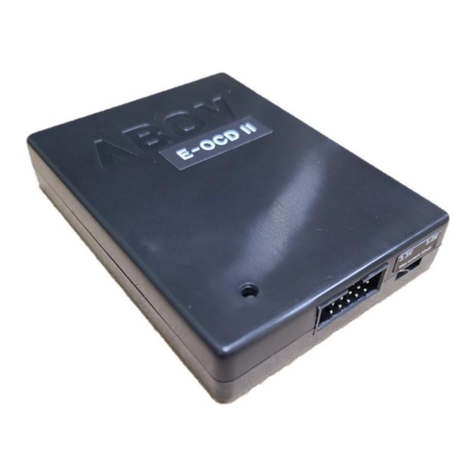
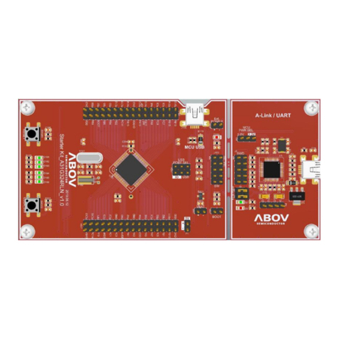
Abov A31G32x User manual

Contents A31G32x USB Bootloader quick guide
2
Contents
1Introduction ....................................................................................................................................5
2User requirements..........................................................................................................................6
2.1 Hardware.............................................................................................................................6
2.1.1 Starter Kit................................................................................................................6
2.1.2 Shield Board ...........................................................................................................6
2.2 Software ..............................................................................................................................7
2.3 Reference documents .........................................................................................................7
2.4 System requirements ..........................................................................................................8
2.5 ABOV website .....................................................................................................................8
3User Bootloader environment & concept .......................................................................................9
4Memory map ................................................................................................................................10
5USB User Bootloader protocol .....................................................................................................11
5.1 Outgoing packet definition.................................................................................................11
5.2Data packet structure ........................................................................................................11
5.3 Host command list.............................................................................................................12
5.3.1 ERS_SN (Erase Sector Number) .........................................................................12
5.3.2 ERS_MC (Erase Macro).......................................................................................12
5.3.3 SET_DB (Set Data Block) ....................................................................................12
5.3.4 PGM_DB (Program Data Block)...........................................................................13
5.3.5 GET_CS (Get CheckSum) ...................................................................................13
6Bootloader programming procedure ............................................................................................14
7User Bootloader project ...............................................................................................................15
7.1 Bootloader project .............................................................................................................15
7.2 Bootloader project – hex to array ......................................................................................17
7.3 Application project .............................................................................................................19
8Example of User Bootloader for USB ..........................................................................................22
8.1 Building and running project..............................................................................................22
8.2 Prepare the Starter Kit ......................................................................................................23
8.2.1 Hardware components of the Starter Kit ..............................................................23
8.3 Set up the Starter Kit .........................................................................................................24
8.3.1 Set jumpers to control the Starter Kit ...................................................................24
8.4 Connect the Starter Kit to your PC....................................................................................25
8.4.1 PC connection via USB on the Starter Kit ............................................................25
8.5 Compile & firmware update as User Bootloader project ...................................................26
8.5.1 Run the Bootloader project...................................................................................26
8.5.2 Compiling the Bootloader & application project ...................................................27
8.5.3 Download the Bootloader .....................................................................................28
8.5.4 Update firmware as USB User Bootloader ...........................................................29
8.5.5 Check the updated application operation .............................................................31
Revision history .....................................................................................................................................32

A31G32x USB Bootloader quick guide List of figures
3
List of figures
Figure 1. A31G32x Starter Kit Board (Hardware) ...................................................................................6
Figure 2. A31G32x Shield Board (Hardware) .........................................................................................6
Figure 3. Compiler (Software) .................................................................................................................7
Figure 4. Reference Documents .............................................................................................................7
Figure 5. Window PC & Mini-B Cable .....................................................................................................8
Figure 6. ABOV Semiconductor Website ................................................................................................8
Figure 7. User Bootloader Environment and Concept ............................................................................9
Figure 8. A31G32x Flash Memory Map ................................................................................................10
Figure 9. Bootloader Programming Procedure .....................................................................................14
Figure 10. startup_(DeviceName)_bootkeil.s........................................................................................15
Figure 11. main.c...................................................................................................................................15
Figure 12. Example of A31G32x Keil Option for Target ........................................................................16
Figure 13. Bootloader Project – Step1..................................................................................................17
Figure 14. Bootloader Project – Step2..................................................................................................17
Figure 15. Bootloader Project – Step3..................................................................................................18
Figure 16. Bootloader Project – Step4..................................................................................................18
Figure 17. Add bootcode.c in Application Project – A31G32x...............................................................19
Figure 18. Example of Setting Options for Target in Application Project – A31G32x ...........................20
Figure 19. Example of bootcode.c File Option in Application Project – A31G32x ................................21
Figure 20. Starter Kit B/D ......................................................................................................................23
Figure 21. Starter Kit Jumper & Switch .................................................................................................24
Figure 22. Starter Kit and USB Connection ..........................................................................................25
Figure 23. USB Input Device at Device Manager .................................................................................25
Figure 24. Open “User_bootloader_for_USB” Project ..........................................................................26
Figure 25. Compile Result on uVision5 (User Bootloader for USB Project) .........................................27
Figure 26. Check to User Bootloader for USB Project Setting .............................................................28
Figure 27. Download User Bootloader for USB Project on A-Link........................................................28
Figure 28. Starter Kit B/D ......................................................................................................................29
Figure 29. Run QuickWriter (PC tool) for USB......................................................................................30
Figure 30. Check the Updated Application Operation...........................................................................31

List of tables A31G32x USB Bootloader quick guide
4
List of tables
Table 1. Command Packet Description.................................................................................................11
Table 2. Data Packet Description ..........................................................................................................11
Table 3. Operation Command Packet Description ................................................................................12

A31G32x USB Bootloader quick guide 1. Introduction
5
1Introduction
This document introduces a method to use USB User Bootloader, and offers an easy way to develop
the ABOV 32-bit Cortex-M0x MCUs. By reading through this document, you will learn how to operate
A31G32x USB User Bootloader with examples, step by step.
1. Starter Kit board has a CMSIS-DAP debugger called “A-Link”, which eliminates the need for
additional devices for MCU programming and debugging.
2. User Bootloader can update user application code of MCU flash through USB communication
between PC and MCU.
3. User Bootloader consists of bootloader project, application project and PC download S/W.

2. User requirements A31G32x USB Bootloader quick guide
6
2User requirements
2.1 Hardware
2.1.1 Starter Kit
Figure 1. A31G32x Starter Kit Board (Hardware)
2.1.2 Shield Board
Figure 2. A31G32x Shield Board (Hardware)

A31G32x USB Bootloader quick guide 2. User requirements
7
2.2 Software
1. Keil complier (uVision5)
2. Keil MDK5 software pack (including Starter Kit sample code) or EVK software
Figure 3. Compiler (Software)
2.3 Reference documents
1. Starter Kit Quick Guide
2. Starter Kit HW Manual
3. Starter Kit Schematic
4. Product User’s Manual
5. Example Code
Figure 4. Reference Documents

2. User requirements A31G32x USB Bootloader quick guide
8
2.4 System requirements
1. Windows PC (7, 8, 10)
2. USB mini-B type cable
Figure 5. Window PC & Mini-B Cable
2.5 ABOV website
For detailed information about corresponding software and documents, you can visit our website at
https://www.abovsemi.com.
Figure 6. ABOV Semiconductor Website

A31G32x USB Bootloader quick guide 3. User Bootloader environment & concept
9
3User Bootloader environment & concept
Figure 7. User Bootloader Environment and Concept
①Bootloader Project makes Boot code file in Keil environment.
②The application project has user code and boot code generated from the boot project.
③Program the hex file created in the application project to MCU.
④If a new application hex file is created, it can be downloaded through USB
⑤Perform download software on your computer.
⑥Connect the PC and the board where the application hex file is initially programmed. Download
to USB using the download software. And check the action.

4. Memory map A31G32x USB Bootloader quick guide
10
4Memory map
Flash Memory area Division
1. BOOT ZONE
①Boot code storage area to rewrite APPLICATION ZONE
②Re-write Impossible
③BOOT ZONE size : 4KB
2. APPLICATION ZONE
①User code area
②Re-write possible through Boot code
Figure 8. A31G32x Flash Memory Map

A31G32x USB Bootloader quick guide 5. USB User Bootloader protocol
11
5USB User Bootloader protocol
5.1 Outgoing packet definition
Inline programmers take commands from the host to upgrade, inspect, and execute the program.
Instructions of inline programmers have a defined data frame format, and the code used here is as
follows:
Table 1. Command Packet Description
CMD
HEXA
Description
SOH
0x01
Start-of-Header
EOT
0x04
End-of-Transmission
ACK
0x06
Acknowledge
NAK
0x15
No-Acknowledge
SYN
0x16
Synchronization
CAN
0x18
Cancel
5.2 Data packet structure
Data packet structure used by the inline programmer is shown in Table 2.
Table 2. Data Packet Description
Offset
Size
Division
Contents
Description
0
1
Start
SOH(0x01)
Start transmission
1
1
Info
0x31
Packet version ID
2
1
0x00
Always 0x00
3
1
CMD
Command
4
1
Data Size(H)
Data size high byte
5
1
Data Size(L)
Data size low byte
6
Data Size
Data
Data
Data body
Size + 6
1
Checksum
CheckSum(H)
Packet checksum high byte
(Except SOH)
Size + 7
1
CheckSum(L)
Packet Checksum low byte
(Except SOH)
Size + 8
1
End
EOT(0x04)
End transmission
NOTES:
1. Packet checksum means the sum of all data from packet version to data except SOH.
2. All data is processed by Big-endian.

5. USB User Bootloader protocol A31G32x USB Bootloader quick guide
12
5.3 Host command list
In-line programmers have the following instructions for handling each action.
Table 3. Operation Command Packet Description
CMD
HEX
Description
Remark
RESET
0xA5
Reset MCU
ERS_SN
0xE1
Erase internal flash sector
ERS_MC
0xEA
Clear internal flash macro
SET_DB
0x8B
Write data buffer block (data transfer)
PGM_DB
0x9B
Program the buffer to the internal flash
GET_CS
0xCC
Read internal flash checksum
5.3.1 ERS_SN (Erase Sector Number)
Description: Erase the specified sector of the ROM file.
Argument: 32-bit (4 bytes) address value (MSB First)
SOH
Packet Header
CMD=0xE1
size=0x0004
Addr(HH)
Addr(HL)
Addr(LH)
Addr(LL)
EOT
Return: ACK (0x06)
5.3.2 ERS_MC (Erase Macro)
Description: Erase the entire ROM file.
Argument: 32-bit (4 bytes) address value (MSB First)
SOH
Packet Header
CMD=0xEA
size=0x0004
Addr(HH)
Addr(HL)
Addr(LH)
Addr(LL)
EOT
Return: ACK (0x06)
5.3.3 SET_DB (Set Data Block)
Description: Write a value to a data buffer block.
Argument: 1024-byte send data value
SOH
Packet Header
CMD=0x12
size=0x0400
Data[0]
Data[1]
Data[2]
…
Data[1023]
EOT
Return: ACK (0x06)

A31G32x USB Bootloader quick guide 5. USB User Bootloader protocol
13
5.3.4 PGM_DB (Program Data Block)
Description: Write the value written to the data buffer block to the designated flash address.
Arguments: 32-bit (4 bytes) address + 32-bit (4 bytes) size (MSB First)
SOH
Packet Header
CMD=0xC0
size=4+PGM size
PGM Base Address
PGM Block Size
EOT
Return: ACK (0x06)
5.3.5 GET_CS (Get CheckSum)
Description: Check the checksum of the internal ROM file. Arguments: 32-bit (4 bytes) address + 32-bit
(4 bytes) size (MSB First)
SOH
Packet Header
CMD=0xDC
size=0x0008
CS Base Address
(4-Byte)
CS Block Size
(4-Byte)
EOT
Return: ACK (0x06) + CS MSB + CS LSB

6. Bootloader programming procedure A31G32x USB Bootloader quick guide
14
6Bootloader programming procedure
Figure 9. Bootloader Programming Procedure

A31G32x USB Bootloader quick guide 7. User Bootloader project
15
7User Bootloader project
Refer to “A31G32x_USB_user_bootloader” project. This project supports example source with a PC
GUI tool and the USB User Bootloader.
This section describes the detailed guide of the USB User Bootloader.
7.1 Bootloader project
Directory: DeviceName_keil_bootcode →bootcode project
1. startup_(DeviceName)_bootkeil.s
①Application Start Address definition (Boot Area is ‘0x0000 ~ 0x0FFF’)
②Jump to Application using _fjump
Figure 10. startup_(DeviceName)_bootkeil.s
2. main.c
①Defined as extern in “c” file
Figure 11. main.c
AREA |.text|, CODE, READONLY
; jump application start
_fjump PROC
EXPORT _fjump
ldr r0, = 0x1000 ; application stack point location
ldr r0, [r0]
mov sp, r0
ldr r0, = 0x1004 ; application program start location
ldr r0, [r0]
bx r0
NOP
NOP
NOP
NOP
ENDP
//// Assembly jump code
extern void _fjump(void);
…
_fjump();

7. User Bootloader project A31G32x USB Bootloader quick guide
16
3. Compiler Setting
①There is no special configuration and the output file name (hex file) should be “bootcode”.
②The file name is “bootcode” for use in the application project.
③The bootcode hex file is converted into an array and made into one C file, where the C
file name is the same as the hex file name.
④Because we include bootcode.c in Project, use the same name for convenience.
Figure 12. Example of A31G32x Keil Option for Target

A31G32x USB Bootloader quick guide 7. User Bootloader project
17
7.2 Bootloader project –hex to array
How to convert compiled hex file to array
1. Convert using OutputArray.exe
2. File Location : DeviceName_keil_bootcode\Boot_Examples\Hex2Array\OutputArray.exe
Figure 13. Bootloader Project –Step1
Figure 14. Bootloader Project –Step2

7. User Bootloader project A31G32x USB Bootloader quick guide
18
Figure 15. Bootloader Project –Step3
Figure 16. Bootloader Project –Step4

A31G32x USB Bootloader quick guide 7. User Bootloader project
19
7.3 Application project
Directory: DeviceName_keil_application -> Examples -> APP (APP code area)
1. Main.c
①Redefine Application Vector Offset.
__disable_irq();
SCB->VTOR = 0x00001000; //Vector Table Offset Register
2. bootcode.c
①Include C file converted from hex file to the Project (added to example project already).
②If there is a change in the bootloader project, update it.
Figure 17. Add bootcode.c in Application Project –A31G32x

7. User Bootloader project A31G32x USB Bootloader quick guide
20
3. Compiler Settings
①Set Application start address in IROM1 and Bootcode area in IROM2.
②Select the Hex file creation option (For use in UART downloader).
Figure 18. Example of Setting Options for Target in Application Project –A31G32x
Table of contents
Other Abov Computer Hardware manuals
Popular Computer Hardware manuals by other brands

COLENTA
COLENTA FNDX 9000 Service manual

VersaLogic
VersaLogic VL-586-1kn Reference manual

Digital Equipment
Digital Equipment PDP16-M user guide

Silicon Laboratories
Silicon Laboratories SLWSTK6240A user guide

Acrosser Technology
Acrosser Technology AND-DNV3N3-R Series user manual

SeaLevel
SeaLevel ULTRA COMM+I.PCI 7103 user manual