Contents
Chapter 1. Starter kit board overview. . . . . . . . . . . . . . . . . . . . . . . . . . . . . . . 4
Chapter 2. A-Link part . . . . . . . . . . . . . . . . . . . . . . . . . . . . . . . . . . . . . . . 5
Chapter 3. Device part . . . . . . . . . . . . . . . . . . . . . . . . . . . . . . . . . . . . . . . 6
3.1. Power/boot mode selector & switch . . . . . . . . . . . . . . . . . . . . . . . 6
3.2. LED display (D101 – D106) . . . . . . . . . . . . . . . . . . . . . . . . . . . 7
3.3. Pin assignment . . . . . . . . . . . . . . . . . . . . . . . . . . . . . . . . . . 8
List of Figures
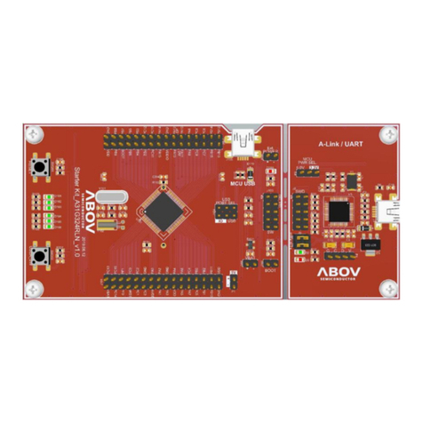
Figure1 StarterKitboard ..................................... 4
Figure2 A-Linksection....................................... 5
Figure 3 Power/boot mode and switch . . . . . . . . . . . . . . . . . . . . . . . . . . . . . . 6
Figure4 LEDschematic...................................... 7
Figure5 LEDdisplay........................................ 7
Figure6 Pinassignment...................................... 8
List of Tables
Table 1 Main features of starter Kit board . . . . . . . . . . . . . . . . . . . . . . . . . . . . 4
Table2 JTAGpindescription................................... 5
Table 3 A-Link SWD pin description . . . . . . . . . . . . . . . . . . . . . . . . . . . . . . . 5
Table 4 Power selection switch description . . . . . . . . . . . . . . . . . . . . . . . . . . . 5
Table5 USBtoUARTdescription ................................ 5
Table 6 JP1 description and connection . . . . . . . . . . . . . . . . . . . . . . . . . . . . . 6
Table7 JP2bootmodeselector ................................. 6
Table 8 S1 & S2 description and function . . . . . . . . . . . . . . . . . . . . . . . . . . . . 6
Table9 LEDpindescription.................................... 7
Version 1.0.0 Page 3 / 8 Starter Kit Hardware A34M418YLN v1.2


