Abov A31T21 RLN Series User manual

Contents A31T21xRLN Shield Board Quick Guide
2
Contents
1Introduction ....................................................................................................................................5
2User Requirements ........................................................................................................................6
2.1 Hardware.............................................................................................................................6
2.2 Software ..............................................................................................................................7
2.3 Reference Documents ........................................................................................................8
2.4 System Requirements.........................................................................................................9
2.5 ABOV Website ..................................................................................................................10
3Build and Run Project (Shield Board) ..........................................................................................11
3.1 Prepare Starter Kit and Shield Board................................................................................12
3.1.1 Hardware Components of Starter Kit ...................................................................12
3.1.2 Hardware Components of Shield Board ...............................................................13
3.2 Starter Kit and Shield Board Settings ...............................................................................14
3.2.1 Jumper Settings for Starter Kit Control.................................................................14
3.2.2 Starter Kit Connection for Shield Board Use ........................................................15
3.3 Starter Kit Connection to PC .............................................................................................16
3.3.1 USB Connection with USB 2.0 Cable...................................................................16
3.3.2 Hardware Recognition on PC (Device Drivers) ....................................................17
3.4 Run Starter Kit Shield Board .............................................................................................18
3.4.1 Compilation with Keil uVision 5 ............................................................................18
3.4.2 A-Link Debugger Configuration and Download ....................................................20
3.5 Debugging .........................................................................................................................22
3.6 Library Description ............................................................................................................24
3.6.1 user.h ....................................................................................................................24
3.6.2 main.c ...................................................................................................................36
Revision History ....................................................................................................................................50

A31T21xRLN Shield Board Quick Guide List of Figures/ List of Tables
3
List of Figures
Figure 1. A31T21xRLN Starter Kit Board (Hardware).............................................................................6
Figure 2. A31T21xRLN Shield Board (Hardware)...................................................................................6
Figure 3. Compiler (Software) .................................................................................................................7
Figure 4. Reference Document on the ABOV Website ...........................................................................8
Figure 5. Window PC and Mini-B Cable .................................................................................................9
Figure 6. Software and Documents at ABOV Semiconductor Website ................................................10
Figure 7. Starter Kit Board ....................................................................................................................12
Figure 8. Components of A31T21xRLN Shield Board ..........................................................................13
Figure 9. Starter Kit Jumper and Switch ...............................................................................................14
Figure 10. Connection of Starter Kit Board and Shield Board ..............................................................15
Figure 11. Starter Kit and USB Connection ..........................................................................................16
Figure 12. Serial Bus Controller Lists at Device Manager ....................................................................17
Figure 13. Project Open in Keil uVision 5 .............................................................................................18
Figure 14. Project Build in Keil uVision 5 ..............................................................................................19
Figure 15. Debugger Settings for Example Project Options .................................................................20
Figure 16. Firmware Download and Verification Result ........................................................................21
Figure 17. Debugging with ABOV A-Link and CMSIS-DAP ..................................................................22
Figure 18. T-type and M-type LEDs for Touch and Display ..................................................................23
Figure 19. Touch/LED Time-division Mode ...........................................................................................24
Figure 20. Touch/LED Independent Mode ............................................................................................25
Figure 21. Hold Key release Event .......................................................................................................26
Figure 22. Touch key Priority define......................................................................................................27
Figure 23. Single-Multi Touch key type define ......................................................................................28
Figure 24. Touch CH POS Noise THD value define .............................................................................29
Figure 25. Touch CH Group define .......................................................................................................30
Figure 26. Serial register select option .................................................................................................31
Figure 27. Touch CH Activation.............................................................................................................33
Figure 28. LED COM/SEG Port Activation ............................................................................................34
Figure 29. Touch CH Activation.............................................................................................................35
Figure 30. Sensitivity for Each Channel in Normal Mode .....................................................................36
Figure 31. Sensitivity for Each Channel in Adjust Mode .......................................................................37
Figure 32. CH_SHIELD_DIS, MESH_SHIELD_DIS .............................................................................39
Figure 33. CH_SHIELD_EN, MESH_SHIELD_EN ...............................................................................39
Figure 34. Touch Data Changes according to SUM_COUNT...............................................................40
Figure 36. Press Threshold and Release Threshold ............................................................................41
Figure 35. Base-line Tracking ...............................................................................................................42
Figure 37. Reverse Situation Parameters .............................................................................................43
Figure 39. IIR-filter ................................................................................................................................44
Figure 38. Debounce Count ..................................................................................................................44
Figure 40. Touch/LED Time-division Operation ....................................................................................46
Figure 41. Touch Key Value Assignment...............................................................................................47
Figure 42. Source Code: user.h ............................................................................................................48
Figure 43. Source Code : main() in main.c ...........................................................................................49

A31T21xRLN Shield Board Quick Guide 1. Introduction
5
1 Introduction
A31T21xRLN Shield Board Quick Guide introduces software environment and development
recommendations for the ABOV 32-bit Touch/LED-Driver MCU Starter Kit. This document also offers
an easy method to develop the Home Appliance Touch.
The Starter Kit Board in this document contains a CMSIS-DAP debugger ‘A-Link’, which allows the
MCU programming and debugging without additional devices.
By following the steps guided in this document, users can build a project and download firmware using
the Keil uVision 5, and learn how to debug the Starter Kit with the A-Link debugger.
In addition, we discuss how to operate the A31T21xRLN Shield Board with examples, step by step.

A31T21xRLN Shield Board Quick Guide 2. User Requirements
7
2.2 Software
The software users must prepare is as follows:
Keil complier (uVision 5)
Example Code & Touch Library
Figure 3 shows the uVision Editor that includes all standard features of a modern source code editor
and is available during debugging.
Figure 3. Compiler (Software)

2. User Requirements A31T21xRLN Shield Board Quick Guide
8
2.3 Reference Documents
From the ABOV website, users can find more information about the A31T21xRLN Starter Kit and Shield
Board as follows:
A31T21x Starter Kit Quick Guide
A31T21x Starter Kit HW Manual
A31T21x User’s Manual
A31T21x T-TYPE LED Structure
Example code
For detailed information, refer to the categories below.
Figure 4. Reference Document on the ABOV Website

A31T21xRLN Shield Board Quick Guide 2. User Requirements
9
2.4 System Requirements
Windows PC (7, 8, and 10)
Micro-B 5-pin USB Cable (for Starter Kit)
Figure 5. Window PC and Mini-B Cable

A31T21xRLN Shield Board Quick Guide 3. Build and Run Project (Shield Board)
11
3 Build and Run Project (Shield Board)
Running application code makes it easier to start the Shield Board. Following the steps below:
Step 1. Prepare Starter Kit and Shield Board.
Step 2. Starter Kit and Shield Board settings
Step 3. Starter Kit connection to PC
Step 4. Run Starter Kit Shield Board.
Step 5. Debugging
Step 6. Library description

3. Build and Run Project (Shield Board) A31T21xRLN Shield Board Quick Guide
12
3.1 Prepare Starter Kit and Shield Board
3.1.1 Hardware Components of Starter Kit
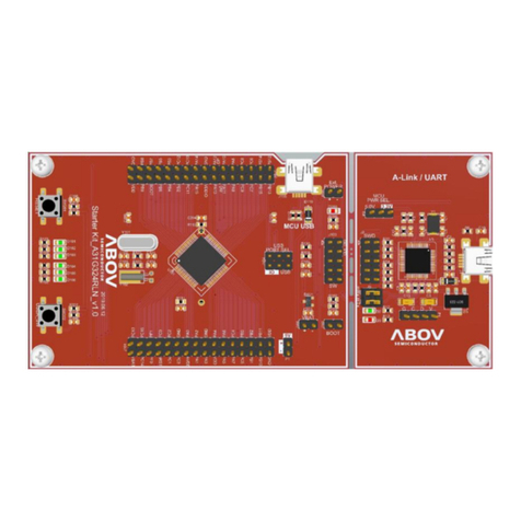
1. The Starter Kit consists of a device board and an A-Link (CMSIS-DAP) debugger board as
shown in Figure 7. It can be used separately as needed.
2. Device board configuration:
A. ABOV 32-bit MCU, X-TAL (optional)
B. Pin headers connected to MCU
C. LEDs and switches to check input/output
3. A-Link (DMSIS-DAP/UART) debugger board configuration:
A. Programmable and debuggable A-Link with connections to PC via USB
B. UART Tx/Rx channel support
Figure 7. Starter Kit Board

A31T21xRLN Shield Board Quick Guide 3. Build and Run Project (Shield Board)
13
3.1.2 Hardware Components of Shield Board
Table 1. Shield Board Description
Function
Description
Remark
Touch (CS0 to CS13)
Touch only
-
Touch (CS14 to CS20, and
CS23)
Touch & SEG
-
Touch (CS20 to CS22)
COM only
Touch Not Available
LED T-Type Matrix
8 x 7 LEDs
ISEG0_ICOM0 to ISEG5_ICOM5,
ISEG7_ICOM7 to ISEG8_ICOM8
LED M-Type Matrix
8 x 8 LEDs
SEG: ISEG6, ISEG9 to ISEG15
COM: ICOM0 to ICOM5, ICOM7 to ICOM8
Figure 8. Components of A31T21xRLN Shield Board

3. Build and Run Project (Shield Board) A31T21xRLN Shield Board Quick Guide
14
3.2 Starter Kit and Shield Board Settings
3.2.1 Jumper Settings for Starter Kit Control
The circle numbers in Figure 9 represent the order in which the jumpers are set to control the Starter
Kit:
1. The Starter Kit uses the USB power. Select 3.3V or 5.0V. (See specifications for the maximum
operating voltage.)
2. Boot mode: ‘Open’ allows User program operating mode (default) and ‘Short’ allows Boot
mode (debugger is always enabled).
3. USB to UART Connector
A. Set jumpers to use UART through the USB connector on the A-Link board.
B. Use to connect UART Rx and Tx.
Figure 9. Starter Kit Jumper and Switch

A31T21xRLN Shield Board Quick Guide 3. Build and Run Project (Shield Board)
15
3.2.2 Starter Kit Connection for Shield Board Use
Connect the header sockets on the Shield board and the header pin on the Starter Kit Board, as shown
in Figure 10.
Figure 10. Connection of Starter Kit Board and Shield Board

3. Build and Run Project (Shield Board) A31T21xRLN Shield Board Quick Guide
16
3.3 Starter Kit Connection to PC
3.3.1 USB Connection with USB 2.0 Cable
Connect a USB 2.0 (Micro-B type) cable to the Starter Kit as shown in Figure 11. When the PC is
connected correctly to the other end of the USB 2.0 cable, the following actions are performed:
1. The power LED on the device board is turned on.
2. The status LED on the A-Link board (debugger) is turned on.
Figure 11. Starter Kit and USB Connection

A31T21xRLN Shield Board Quick Guide 3. Build and Run Project (Shield Board)
17
3.3.2 Hardware Recognition on PC (Device Drivers)
The A-Link board (debugger) uses a USB interface.
When the A-Link board (debugger) is connected to a PC, it is displayed as ‘USB Composite Device’ in
the Serial Bus Controller List, as shown in Figure 12.
The A-Link does not require the driver installation on Microsoft Windows.
Figure 12. Serial Bus Controller Lists at Device Manager

3. Build and Run Project (Shield Board) A31T21xRLN Shield Board Quick Guide
18
3.4 Run Starter Kit Shield Board
3.4.1 Compilation with Keil uVision 5
Using Keil uVision 5, users can compile the provided project files and run the Starter Kit Shield Board.
To do so, follow the procedure below:
1. Install ‘Keil uVision 5 for Cortex-M’.
2. Open the provided project file (A31T21x.uvmpw).
Figure 13. Project Open in Keil uVision 5

3. Build and Run Project (Shield Board) A31T21xRLN Shield Board Quick Guide
20
3.4.2 A-Link Debugger Configuration and Download
When the compilation is completed without errors, users can begin programming the Starter Kit.
Downloading is enabled since the Starter Kit is connected to the USB port on the PC.
Debugger Configuration
Before downloading firmware to the target, the A-Link debugger must be configured in options panel of
the project as shown in Figure 15.
The circle numbers in Figure 15 represent the order in which the A-Link debugger is set:
Figure 15. Debugger Settings for Example Project Options
1. On the Debug tab, check if the CMSIS-DAP Debugger is selected. The A-Link debugger uses
the CMSIS-DAP Debugger Interface.
2. Click the ‘Settings’ button and check if the A-Link CMSIS-DAP is selected on the Debug tab of
the newly opened window.
3. When the A-Link debugger is well connected to the target board, the target IDCODE and
Device Name are displayed in the SWDIO field of the SW Device menu.
4. On the Flash Download tab, check if the flash loader of the device is displayed correctly.
Other manuals for A31T21 RLN Series
1
Table of contents
Other Abov Computer Hardware manuals
Popular Computer Hardware manuals by other brands

COLENTA
COLENTA FNDX 9000 Service manual

VersaLogic
VersaLogic VL-586-1kn Reference manual

Digital Equipment
Digital Equipment PDP16-M user guide

Silicon Laboratories
Silicon Laboratories SLWSTK6240A user guide

Acrosser Technology
Acrosser Technology AND-DNV3N3-R Series user manual

SeaLevel
SeaLevel ULTRA COMM+I.PCI 7103 user manual