manuals.online logo
Brands
  1. Home
  2. •
  3. Brands
  4. •
  5. Abra
  6. •
  7. Educational Equipment
  8. •
  9. Abra AK-120 User manual

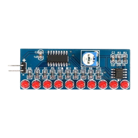
Abra AK-120 User manual

Parts List
D.I.Y L.E.D Cube with Touch Function
Level: Expert AK-120
A brief Intro to SMT/SMD Recommended Tools
Touch Functions
So far the components that were selected are
all 0805 SMT package size. This is a common
dimension for Surface mount components.
Along with the 0603, theses will be the
common dimensions you may encounter with
the introduction to surface mounting.
The Resistors are usually denoted with a black
body and a number written across the unit to
reveal its value. Capacitors on the other hand
have a beige body and no writing on them. So
you don’t want to drop or mix them up.
When soldering, keep all the components in
their packaging and avoid using a de-soldering
pump as the tiny components can be sucked up
from the pump.
Work over a clean environment or you may end
up spending the entire build time looking for
the components.
SL-30 Soldering Station with controllable temp
SL-624 Screwdriver Soldering Tip
835-P Flux
8241-T Isopropyl Alcohol
4140-P Flux Remover
DW5 Solder Wick
TOL-09161 Solder 60/40
H-HANDS-DEL Helping Hands
K1: Each time you press the system will sequence
to a new pattern.
K2: The first press should playback the second
press recording.
The second press will allow you to talk or tap the
microphone to vary the light sequence.
The third press will be affected by the photo-
resistor value.
Soldering Guide
PART A
1) Flip the board to reveal the SMD Side of the board.
2) It is recommended to clean the board with isopropyl Alcohol.
3) Place some flux over the pads that need to be soldered.
4) Place the Mini-B USB jack onto the board and using a soldering iron and some solder, solder the first and last pin
of the Mini-B USB jack only. (2-3-4 are for data, not required for this design)
5) You may want to use a screwdriver tip for your soldering iron and leave the temperature at 250°C.
6) Solder the side pads for the connector to secure the unit in place, it is recommended not to push down on the
unit when soldering. Ensure you pull your iron away from the component creating a stroking movement for the
solder to set on, this will also remove any solder joints it may accidently create.
7) Proceed again with the same cleaning habit in step 2 and step 3 over U1 on the PCB. Place the IC over U1 make
sure the black dots align.
8) Place a small amount of solder over the 1st pin, 14th, 15th and 28th pin. Solder theses pins into place over the
pad. Now the unit will not move you can proceed to solder the rest of the pins using some solder and the
spreading motion, allow the heat of the tip to set the pins into the pads. This technique if done correctly will
remove solder bridges if they occur. Should a solder bridge occur, you are using too much solder! Using a solder
wick, you can remove excess solder if needed.
9) Add solder and do this to the other pins.
10) Solder the small surface mount capacitors.
11) Repeat and solder the larger capacitor
12) You may now solder the entire resistor by referencing the PCB number back to the parts list.
13) Solder the photo-resistor into place and trim any excess lead if required.
14) According to the image, ensure to solder the microphone with the pin that has three strips towards the black
dot on the PCB.
15) You may now add four standoffs and flip the board
PART B
1) Place the led for the first level on the board. Make sure the short pin goes into the numbered boxes shown
below.

2) Keeping the entire unit leveled, you can rotate the board and place the unit to remain flat over your work area.
Solder the pins into place and connect the Mini-B USB cable to the computer.
3) All lights should light up, if not. Please flip over the board and remove the defective led or check the USB port is
properly soldered.
4) Once the first level is function you will now begin on level 2, 3 and 4.
5) Orient the board to the front side of PCB with the Logo opposite to you. If you did this correctly K1 and K2
should be on your left.
6) Push the board aside and take an L.E.D, place shortest pin to your left side flat on your table. Take another LED
and solder the two leads avoiding the middle one. It should look something like this:
7) Repeat this format 8 more times, they need to have only three L.E.Ds stacked!
8) Keeping the left lead as the shortest, bend the middle pin towards you.
9) Place this stack with the shortest pin going to the number on board and solder left and right leads leaving the middle.
10) The middle lead from the third and second row will now connect with first lead middle lead.
11) Notice how the leads are not cut off, they should be facing towards you!
12) Take the white wire and strip enough to run the entire length across the top three leads.
13) Solder them together and cut the 4th level leads sticking out and feed the other end of the unstripped wire downwards into
the left hole next to the writing 2.
14) Repeat this step for level 3 and place into second hole and again for 2nd level into the final right hole.
15) Flip the board and solder the 4th level to Com4 pad. 3rd to com 3 and 2nd to com 2.
16) Plug in power and it should work, if not try checking the LEDs.

Other Abra Educational Equipment manuals

Abra Theremin Player Kit User manual

Abra

Abra Theremin Player Kit User manual

Abra AK-280 User manual

Abra

Abra AK-280 User manual

Abra AK-72 User manual

Abra

Abra AK-72 User manual

Abra LED FLASHER KIT User manual

Abra

Abra LED FLASHER KIT User manual

Abra AK-125 User manual

Abra

Abra AK-125 User manual

Popular Educational Equipment manuals by other brands

Buki 7250 manual

Buki

Buki 7250 manual

Copernicus PTE78 Assembly guide

Copernicus

Copernicus PTE78 Assembly guide

Kyoto Kagaku M82A instruction manual

Kyoto Kagaku

Kyoto Kagaku M82A instruction manual

Enabling Devices 2249 user guide

Enabling Devices

Enabling Devices 2249 user guide

Nasco Healthcare Lifeform GERi LF04040U manual

Nasco Healthcare

Nasco Healthcare Lifeform GERi LF04040U manual

DVDO DVDO-RS-2 user manual

DVDO

DVDO DVDO-RS-2 user manual

Reality Works 1043115-01 quick start guide

Reality Works

Reality Works 1043115-01 quick start guide

BJ Live SHX Bubble Tube user manual

BJ Live

BJ Live SHX Bubble Tube user manual

Rompa 19210 manual

Rompa

Rompa 19210 manual

KOKEN LM-109MA instruction manual

KOKEN

KOKEN LM-109MA instruction manual

HeartSine samaritan PAD 350P Trainer user manual

HeartSine

HeartSine samaritan PAD 350P Trainer user manual

RS 3.5 quick start guide

RS

RS 3.5 quick start guide

FrontRow LessonCam 12X Configuration guide

FrontRow

FrontRow LessonCam 12X Configuration guide

Microbric Edison Robot manual

Microbric

Microbric Edison Robot manual

LeapFrog ClickStart user manual

LeapFrog

LeapFrog ClickStart user manual

Festo 8085468 operating instructions

Festo

Festo 8085468 operating instructions

Rompa 20019 manual

Rompa

Rompa 20019 manual

Sphero specdrums SD01 Series user manual

Sphero

Sphero specdrums SD01 Series user manual

manuals.online logo
manuals.online logoBrands
  • About & Mission
  • Contact us
  • Privacy Policy
  • Terms and Conditions

Copyright 2025 Manuals.Online. All Rights Reserved.