Tools Required: •Soldering Iron •Solder •Diagonal Cutters •9V Battery
Kit Description:
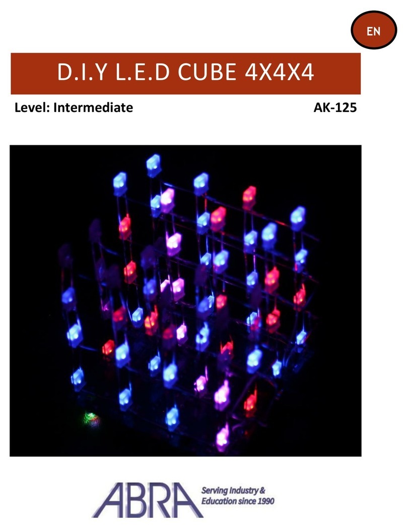
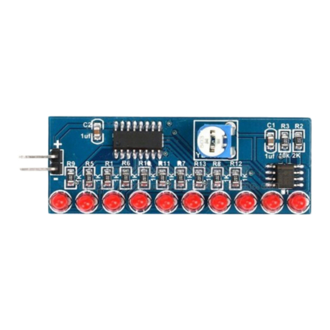
e LED FLASHER KIT alternately ashes two red LEDs.
e ashing rate can be adjusted by varying the resistance of the P1 potentiom-
eter. Timing is provided by the popular 555 integrated circuit.
e 555 timer produces square wave pulses with a frequency that is determined
by the combination of the R1, R2, P1 and C1 values.
Circuit Description:
e circuit is composed of a 555 timer IC which creates square pulses, alternat-
ing between a HIGH and LOW state at pin3. e pulses ash LED1 and LED2.
e frequency of the square pulses are controlled by a time constant deter-
mined by the C1 capacitor, the R1, R2 resistors and the resistance of the P1
potentiometer.
General Assembly Guidelines:
Good soldering technique is the most important factor in successfully assem-
bling your kit.
A small pencil type soldering iron 25-40 Watts is recommended.
e tip of the iron should be kept clean at all times by wiping it oen on damp
sponge or cloth.
Touch the component leadandthesolderpad junctionwiththe solderingirontip.
Apply solder to the junction. It should not take more than 1-2 seconds for the
solder to melt.
A good solder joint will appear shiny and conform to the lead.
Refer to the ABRA website at www.abra-electronics.com using the part number
if you cannot identify a part in the part list.
Parts list:
Item ABRA Part# Description Quantity
IC1 LM555 Single Timer IC 1
SOCKET 8LP Dip Socket for LM555 Timer IC 1
LED1,LED2 LED-5CR Clear Red Diused LED 2
R1, R2 R1/4-10k 10k Ohm Resistor (Brown, Black, Orange) 2
R3, R4 R1/4-220 220 Ohm Resistor (Red, Red, Brown) 2
P1 3386P-1-104 100k Ohm Potentiometer 1
C1 10R16 10uF Polarized Capacitor 1
9V CLIP 29-130 9V Battery Clip 1
PCB LED-Blinky-B LED Flasher Kit PCB 1

