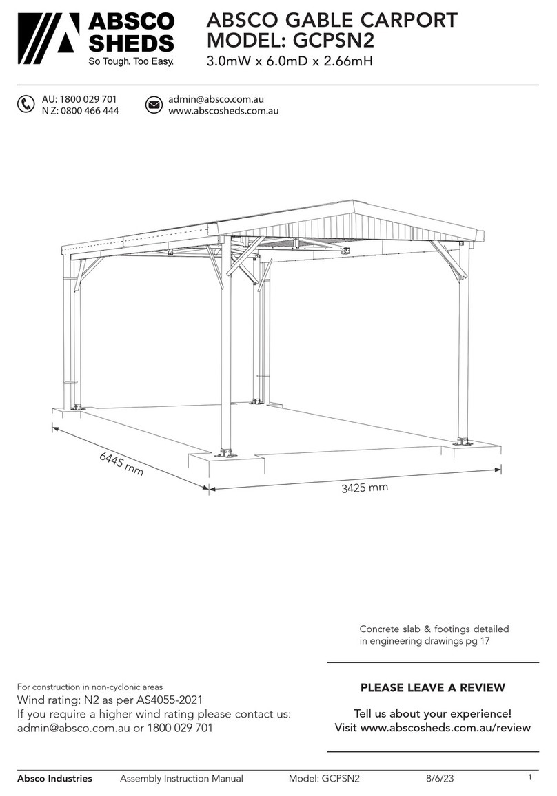
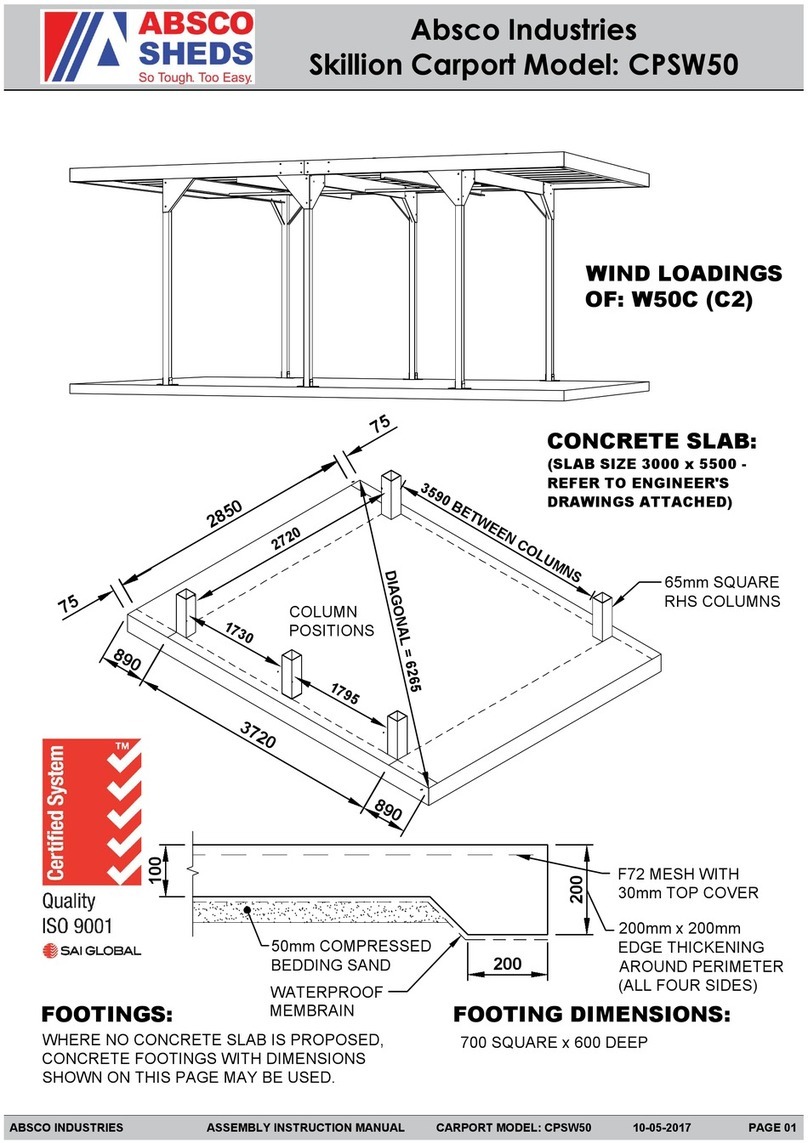
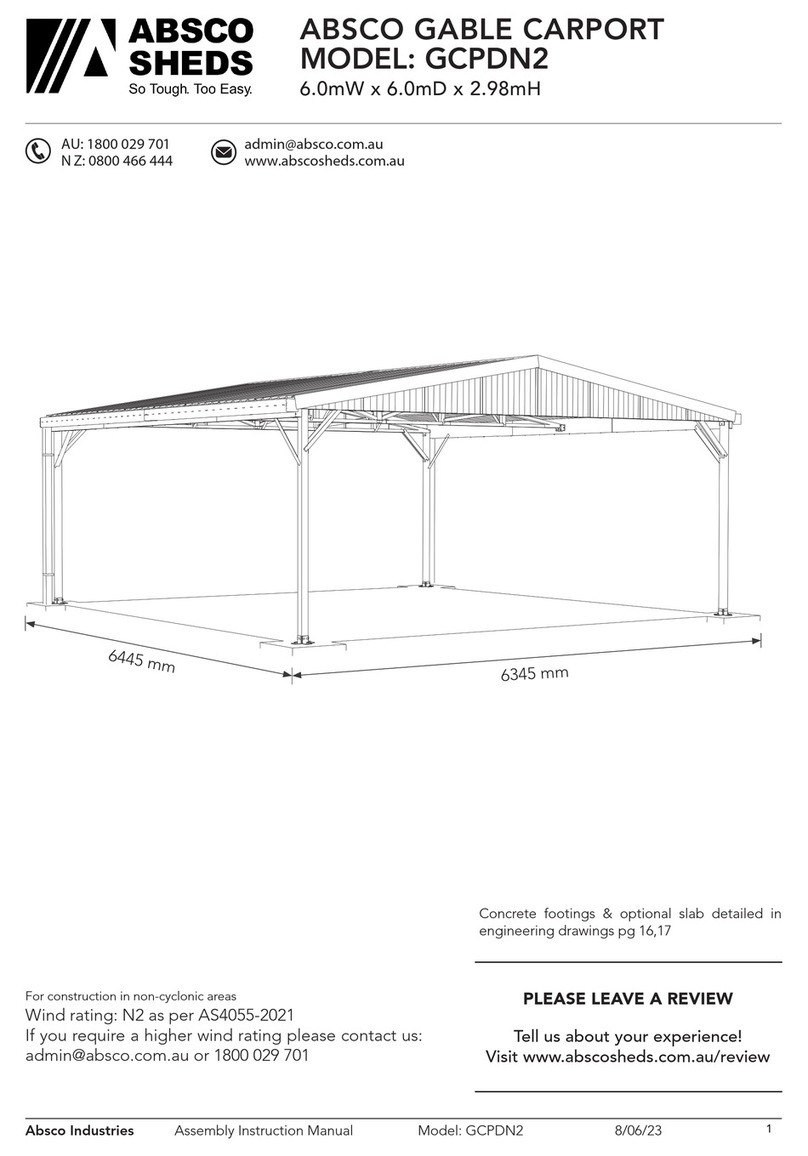
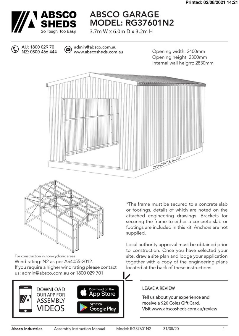
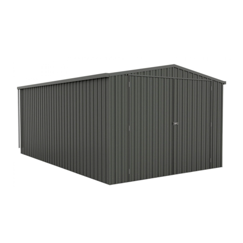
ABSCO SHEDS RG60602N2 User manual

Absco Industries Assembly Instruction Manual
ABSCO GARAGE
MODEL: RG60602N2
6.00mW x 6.00mD x 3.40mH
Model: RG60602N2 22/10/19 1
AU: 1800 029 701
N Z: 0800 466 444
www.abscosheds.com.au
For construction in non-cyclonic areas
Wind rating: N2 as per AS4055-2012.
If you require a higher wind rating please contact
*The frame must be secured to a concrete slab
or footings, details of which are noted on the
attached engineering drawings. Brackets for
securing the frame to either a concrete slab or
footings are included in this kit. Anchors are not
supplied.
Local authority approval must be obtained prior
to construction. Once you have selected your
site, draw a site plan and lodge your application
together with a copy of the engineering plans
located at the back of these instructions.
6070mm
CONCRETE SLAB*
5920mm
Opening widths: 2400mm
Opening heights: 2300mm
Internal wall height: 2830mm
Download the Absco
Sheds Assembly App
for instructional videos
MANU FA CT URED
IN A US TR ALIA
SNAPTiTE
Assemb ly

Absco Industries Assembly Instruction Manual
ABSCO GARAGE
MODEL: RG60602N2
6.00mW x 6.00mD x 3.40mH
Model: RG60602N2 22/10/19 2
Before Getting Started:
• Read these instructions carefully and fully so that an understanding of the steps involved in
construction is obtained. Do this with constant reference to the engineering drawings provided.
• Measure and check off all the components prior to commencement. If a discrepancy is
discovered, contact Absco immediately for assistance.
Part Numbers:
• All framing sections & wall and roof sheets have part numbers printed on them. The remainder
of the components should be identified by their description, size and pictures provided in the
component lists.
Roller Door Instructions and Engineering Certification:
• Absco Industries supplies roller doors from another Australian manufacturer. The instructions to
install the door are supplied with the roller door and are not covered in this document.
• The engineering documentation that certifies the door to the appropriate wind loading is also
supplied by the manufacturer.
Anchor Sets Not Supplied:
• Sleeve anchors are detailed but not supplied with this garage. They can be purchased readily
from most hardware stores. Refer to engineering drawings for further information.
Self Drilling Tek Screws:
• Hex head tek screws (FAST035) are to be used unless noted otherwise.
• Hex head tek screws with neoprene washer (FAST033) are to be used for securing roof sheets to
framework.
• Wafer head tek screws (FAST014) are to be used on the outside of framework to keep these
surfaces as smooth as possible so that sheeting can be secured to them.
• All roof and wall sheets are pan fixed. ie: Screwed through the flat pan of the steel sheeting into
the framework.
Personal Access Door (P.A. Door):
• If you have selected the optional Personal Access Door, P.A. Door, There is an additional
instruction manual that is to be used in conjunction with this document.

Absco Industries Assembly Instruction Manual
ABSCO GARAGE
MODEL: RG60602N2
6.00mW x 6.00mD x 3.40mH
Model: RG60602N2 22/10/19 3
Tools Required:
Tools Recommended:
LADDER
Safety Notes:
• The assembly of this product requires some lifting of heavy objects. Two person lifts are required.
• Some parts have sharp edges and/or corners. The use of gloves and safety shoes is highly
recommended. Pay attention to where these parts can be safely handled most safely, and plan the
handling of these parts before working with them.
• Drilling sheet metal produces small metal shavings the use of safety glasses and the periodic
clearing of these shavings throughout the build is recommended.
• Use the appropriate personal protective equipment for any tool used during the assembly.

Absco Industries Assembly Instruction Manual
ABSCO GARAGE
MODEL: RG60602N2
6.00mW x 6.00mD x 3.40mH
Model: RG60602N2 22/10/19 4
COMPONENTS LIST
QTY COMPONENT
DESCRIPTION
PART
No. CHK QTY COMPONENT
DESCRIPTION
PART
No. CHK
1PHILLIPS HD
DRIVER BIT FAST023 1HEX HD
DRIVER BIT FAST038
200
WAFER HD
TEK SCREW
10-16x16mm
FAST014 1400
HEX HD
TEK SCREW
10-16x16mm
FAST035
200 POP RIVET
4-3 FAST009 400
HEX HD
TEK SCREW W/ NEO
WASHER 10-16x16mm
FAST033
40 PURLIN
BRACKET BKT11 42
MULTI-
PURPOSE
BRACKET
BKT17
2
TRIANGLE
PLATES
150x150mm
ZACO190 2
ROOF
STRAPPING
L=20m
FAST040
6
ANGLE
BRACE
40x40x530mm
ZACO124A 1
CENTRE
MULLION
80x300x3240mm
ZACO215
4
SIDE
MULLION
80x150x2790mm
ZACO216 24
HEX HD
TEK SCREW
14-20x45mm
FAST081
4GUTTER
L=3030mm TR22 2
DOWNPIPE
100x75mm
L=2400mm
TR10
4
BARGE
FLASHING
L=3050mm
TR06 2
RIDGE
CAPPING
L= 3030mm
TR08
2‘L’ FLASHING
L=3030mm TR19 2
ROLLER DOOR
FLASHING
L=3030mm
TR21
4GUTTER
END STOP TR25 2DOWNPIPE STRAP
450x20x0.35mm TR29
1
CENTRE
MULLION CAP
L=2340mm
TR71 2DOWNPIPE
DROP RWG18
16 GUTTER
BRACKET RWG06

Absco Industries Assembly Instruction Manual
ABSCO GARAGE
MODEL: RG60602N2
6.00mW x 6.00mD x 3.40mH
Model: RG60602N2 22/10/19 5
SHEET PACK
QTY COMPONENT
DESCRIPTION
PART
No. CHK QTY COMPONENT
DESCRIPTION
PART
No. CHK
1STEEL SHEET
3386 x 773mm 338L 1STEEL SHEET
3386 x 773mm 338R
1STEEL SHEET
3256 x 773mm 325L 1STEEL SHEET
3256 x 773mm 325R
1STEEL SHEET
3125 x 773mm 312L 1STEEL SHEET
3125 x 773mm 312R
1STEEL SHEET
2995 x 773mm 299L 1STEEL SHEET
2995 x 773mm 229R
1STEEL SHEET
1050 x 773mm 105L 1STEEL SHEET
1050 x 773mm 105R
1STEEL SHEET
920 x 773mm 092L 1STEEL SHEET
920 x 773mm 092R
1STEEL SHEET
790 x 773mm 079L 1STEEL SHEET
790 x 773mm 079R
1STEEL SHEET
660 x 773mm 066L 1STEEL SHEET
660 x 773mm 066R
2STEEL SHEET
2370 x 416mm
RAW EDGE ONE SIDE
237-2 16 STEEL SHEET
3030 x 773mm 303
16 STEEL SHEET
2860 x 773mm 286

Absco Industries Assembly Instruction Manual
ABSCO GARAGE
MODEL: RG60602N2
6.00mW x 6.00mD x 3.40mH
Model: RG60602N2 22/10/19 6
FRAMING SECTIONS 40x80mm - RG60602N2FP
FRONT FRAME see page 8 for frame identication guide
2
FRAME
SECTION
L = 2755mm
C2755 2FRAME
SECTION
L = 2992mm
S2992
2
FRAME
SECTION
L = 2750mm
C2750 4
FRAME
SECTION
L = 1365mm
N1365
4
FRAME
SECTION
L = 2400mm
C2400 6
FRAME
SECTION
L = 260mm
K0260
2
FRAME
SECTION
L = 1140mm
C1140 2
FRAME
SECTION
L = 100mm
C0100
2
FRAME
SECTION
L = 1080mm
C1080
REAR FRAME
2
FRAME
SECTION
L = 3262mm
C3262 2
FRAME
SECTION
L = 2990mm
J2990
2
FRAME
SECTION
L = 2970mm
C2970 2
FRAME
SECTION
L = 2989mm
M2989
2
FRAME
SECTION
L = 2950mm
C2750 8
FRAME
SECTION
L = 1467mm
K1467
2
FRAME
SECTION
L = 100mm
C0100
C
C
C
C
C
C J
C M
C K
C
S
N
K
C

Absco Industries Assembly Instruction Manual
ABSCO GARAGE
MODEL: RG60602N2
6.00mW x 6.00mD x 3.40mH
Model: RG60602N2 22/10/19 7
FRAMING SECTIONS 40x80mm (CONTINUED)
QTY COMPONENT
DESCRIPTION
PART
No. CHK QTY COMPONENT
DESCRIPTION PART No. CHK
INTERNAL FRAMES (IN 3 PACKS)
30
FRAME
SECTION
L = 2990mm
C2990 6FRAME
SECTION
L = 250mm
C0250
12
FRAME
SECTION
L = 2750mm
C2750
PURLINS & SIDE GIRTS
16
FRAME
SECTION
L = 2960mm
C2960 12
FRAME
SECTION
L = 200mm
C0200
4
FRAME
SECTION
L = 100mm
C0100 16
FRAME
SECTION
L = 1450mm
K1450
ROLLER DOOR - RATED FOR N2 WIND LOADING
QTY COMPONENT
DESCRIPTION
PART
No. CHK QTY COMPONENT
DESCRIPTION
PART
No. CHK
2
ROLLER DOOR
FOR 2400W x 2300H
OPENING
RD08 4 ROLLER DOOR
GUIDES -
C C
C
C C
C K

Absco Industries Assembly Instruction Manual
ABSCO GARAGE
MODEL: RG60602N2
6.00mW x 6.00mD x 3.40mH
Model: RG60602N2 22/10/19 8
Frame Section Identification Guide
There are several types of frame section, each featuring a different combination of notches and/or
holes. Frame sections are coded with a letter representing the type of frame section, followed by
the length of the frame section in millimeters.
EG: C2960 = Straight cut both ends with overall length of 2960mm
C-TYPE - Straight cut at both ends
J-TYPE - Straight cut at one end: 20mm tab
notch with holes at other end
K-TYPE - 20mm tab notch with holes at both
ends
L-TYPE - Straight cut at one end: 45mm lip
notch at other end.
N-TYPE - Straight cut at one end: 45mm lip
notch/20mm tab notch with holes at other end
P-TYPE - 45mm lip notch/20mm tab notch with
holes at both ends.
R-TYPE - 45mm lip notch/20mm tab notch with
holes at one end: 90mm lip notch at other end.
S-TYPE - Variable notching and/or holes nominated in parts checklist
M-TYPE - 45mm lip notch at both ends

Absco Industries Assembly Instruction Manual
ABSCO GARAGE
MODEL: RG60602N2
6.00mW x 6.00mD x 3.40mH
Model: RG60602N2 22/10/19 9
COMPONENT OVERVIEW
The frame is constructed from 80mm x 40mm galvanised steel channel, similar to that used in domestic steel
house framing. All sections are cut to exact lengths, with channel ends pre-punched where necessary to simplify
assembly.
Channel sections are secured together using 10G self drilling tek screws (supplied). Roof sheets are secured
to the frame using 10G x self drilling tek screws with neoprene washers (supplied). Barge capping is secured
together using 3mm pop rivets (supplied).
Rear Frame
Page 11
Internal Frames
Page 12
Front Frame
Page 13
Sheeting
Page 22

Absco Industries Assembly Instruction Manual
ABSCO GARAGE
MODEL: RG60602N2
6.00mW x 6.00mD x 3.40mH
Model: RG60602N2 22/10/19 10
Guide for Connecting Frame Sections
Absco sheds’ frame assemblies are supplied with
10-16x16 self drilling wafer head phillips drive tek
screws
The wafer head minimises distortion to the sheet
cladding once it is fitted to the frame
Ensure that driver bits used to fasten these screws
is phillips drive, as similar alternatives (EG. Pozi
drive) increases the risk of stripping the head of
these screws.
Some holes are pre-punched in Absco sheds’ frame
sections, however the wide range of positions that
most fasteners are required for means that the
remainder have to be drilled as per the connection
being made
A 3mm drill bit is supplied for pre-drilling holes
where self drilling screws may be more difficult to
establish holes with (EG. Fitment of purlin brackets).
Absco sheds’ frame sections are manufactured
from light gauge steel, enabling for the notched
ends or lengths of one frame section to be spread
over the sides of another frame section, boxed
frame section or H-section.
Absco sheds’ frame sections are designed to nest
into one another to create boxed frame sections
Boxed frame sections are only required in some
parts of the entire frame assembly
Boxed frame sections are fastened together using
the fast014 tek screws supplied at 300mm centres
(unless otherwise stated) along the length of each
boxed frame section.
Some connections are designed to fasten more than two parts together. Connections may also not
feature a defined alignment or physical stop.
For these reasons, focus on arranging all parts of a frame assembly or subassembly together (to
the overall sizes and check measurements nominated) using minimal screws. This allows for easier
adjustment to various connections which may be necessary to achieve the overall dimensions and
check measurements that are nominated.
Fit the remaining screws once the frame assembly or subassembly is assembled as per the overall
dimensions and check measurements that are nominated
Boxing Frame Sections
A B
HIGH SIDE A
HIGH SIDE B
LOW SIDE B
LOW SIDE A FAST014
FAST014
HIGH SIDE
HIGH SIDE
(PRINT)
(PRINT)
LOW SIDE
LOW SIDE
Absco Industries Assembly Instruction Manual
ABSCO GARAGE
MODEL: RG60602N2
6.00mW x 6.00mD x 3.40mH
Model: RG60602N2 22/10/19 11
Rear Frame
• Box these frame sections together.
1 OFF: C3262 + C3262
2 OFF: C2970 + J2990
• Lay the parts out on your slab or another
level area as shown below.
• Check diagonals for squareness, then join all
components together with tek screws. Make
sure FAST014 are used on exterior side.
• Double check the dimensions and draw an
outline of the frame onto the ground with
chalk to use as a template for the internal
and front frames.
• Use C0100 box the bottom of the two C2750
as shown.
• Turn the frame over carefully & fix the other
side.
* These dimensions are identical for rear, internal and front frames
* 2750
* 1450
* 140
1490 14901470 1470
* 5920
* 3271
* 6525
C3262
C3262
C2970
J2990
C2750
BKT17
C0100
M2989
ZACO190
K1467
8 OFF
Notched end of J2990
to poke out past C2970.
Orientate to top.

Absco Industries Assembly Instruction Manual
ABSCO GARAGE
MODEL: RG60602N2
6.00mW x 6.00mD x 3.40mH
Model: RG60602N2 22/10/19 12
Internal Frame
C2750
C2750
BKT17
C2990
C2990
C2990
C2990
C0250
C0250
C2990
C2990
2750
5920
3271
3 Required.
• All frame sections are boxed.
• Lay the components out so they follow exactly
the chalk outline of the rear frame.
• Locate the boxed horizontal brace centrally
between the top chords and secure with teks
screws.
• To be able to assemble the internal frame the
top chords must be boxed in position on the
frame as the last step. These pieces are shown
on the right in grey.
• Box the top chords.
• Two people will be required to carefully turn
the frame over to fasten teks into the other
side. The frame will flex considerably but will
become more stable when fully fastened
together.

Absco Industries Assembly Instruction Manual
ABSCO GARAGE
MODEL: RG60602N2
6.00mW x 6.00mD x 3.40mH
Model: RG60602N2 22/10/19 13
• Box these frame sections together.
2 OFF: C2400 + C2400
• Assemble the side mullions.
2 OFF: ZACO216 + ZACO216 + C2755
• Lay the components out as shown below, using the
same dimensions as the rear frame. Fix with teks in
the same manner.
• S2992 have cutouts that allow it to fit over the centre
and side mullions and other frame members.
• Take particular notice of the different views below
to determine which way sections fit into others.
Some pieces have end notching that must be
orientated correctly.
• Do not fit the centre mullion trim, TR71, or the
brackets BKT17, used for anchoring the frame to
the slab at this stage.
• Refer to the engineering drawings for further fixing
details.
Front Frame
K0260
C2400
C2400 TR71
C0100
ZACO216
ZACO216
ZACO215
S2992
N1365
C1080
C2750
C2755
C1140
* 1450
2300
2400 2400300410 410
ZACO216 C2755
Flush at base
Open section faces outward
Header beams are
secured by two
BKT17 at either end
Side mullion assembly

Absco Industries Assembly Instruction Manual
ABSCO GARAGE
MODEL: RG60602N2
6.00mW x 6.00mD x 3.40mH
Model: RG60602N2 22/10/19 14
Slab Details and Anchoring Layout
• The garage has been designed so that the slab
and the external dimensions of the frame are the
same. This allows the wall sheeting to overlap the
top of the slab by 30mm and this prevents water
entering the structure.
• If a front stepdown or ramp is added as
recommended be sure to allow for the 30mm
stepdown for the wall sheeting at the entrance.
• Refer to the attached engineering drawings for
footings as an alternative to the slab specified.
5920
Entry 1 Entry 2
5920
6070
Includes 150mm stepdown/ramp
1410 1410 1410141080 8040 40
40 404040
3002400410 4102400
401430 1430 1430 1430
40
8372
150
External frame: 5920 W x 5920 D
Slab with stepdown: 5920 W x 6070 D
Slab without stepdown: 5920 W x 5920 D
250
150
25030
PERIMETER EDGE THICKENING
Applies to all four sides.
FRONT ENTRY STEPDOWN / RAMP
Adds 150mm to slab making it 6070mm front-to-
back as noted above.
F72 Mesh with 30mm
of top cover
50mm of bedding
sand and waterproof
member
3-FT8M
65 Bottom
cover.

Absco Industries Assembly Instruction Manual
ABSCO GARAGE
MODEL: RG60602N2
6.00mW x 6.00mD x 3.40mH
Model: RG60602N2 22/10/19 15
Anchoring Layout
• Fasten the multipurpose brackets (BKT17) to the
frames as shown above while they are laying on
the ground.
• Front and Rear frames will also require the C0100
be boxed into the bottom of both columns.
• Mark out the frame positions according to page
14. Misalignment between frames will result in the
wall girts not fitting properly.
• Secure with tek screws, refer to the engineering
drawing for the quantity of teks per bracket.
• When securing the BKT17 to the slab always use
the bracket hole that is furtherest away from the
slab edge. This will prevent the possibility of the
concrete cracking near the slab edge.
This image only shows the bottom of the frames and is not to scale.
60
EDGE OF SLAB
Rear frame
Front frame
Internal frame 3
Internal frame 2
Internal frame 1
C0100
C0100C0100
C0100

Absco Industries Assembly Instruction Manual
ABSCO GARAGE
MODEL: RG60602N2
6.00mW x 6.00mD x 3.40mH
Model: RG60602N2 22/10/19 16
Frame Construction
0. General Anchoring Method
• To secure each frame to the slab, move the frame to
its marked position. One person will need to hold
the frame in position while another should mark
the inner holes of the anchor brackets (BKT17).
• Move the frame away enough to get tool access
and drill the slab for each anchor.
• Move the frame back into position and secure with
anchor.
1. Rear Frame
• The rear frame can be supported with ropes and
pegs or propped with the roof purlins (C2960)
during this stage.
2. Internal Frame
• The top section of the internal frames will twist
slightly under their own weight. This is normal
for any portal frame design. If you are concerned
with this clamp or screw a roof purlin (C2960) as
shown to act as a temporary prop. This will stop
any twisting until all frames are screwed together.

Absco Industries Assembly Instruction Manual
ABSCO GARAGE
MODEL: RG60602N2
6.00mW x 6.00mD x 3.40mH
Model: RG60602N2 22/10/19 17
Frame Construction
3. Internal Frames
• Secure the first internal frame to the slab
• Fit the four side wall girts (K1450) to the same
height as the rear wall girts.
• Bend the inside tab of the K1450’s to a right angle
so it can be fixed into the rear wall girt. See detail.
• To stabilise the structure secure two wall sheets
as shown. Make sure that each wall sheet (286)
overhangs the slab by 30mm and is 80mm past the
top of the uprights.
• Fixings used for wall sheeting are hex head tek
screws without neoprene washers (FAST035).
Positioned in-line with the girts at every second
sheet pan.
• The wall sheeting should poke out past the
back frame 16.5mm to connect into the rear wall
sheeting later. See page 22 for further detail.
• Use a spirit level to check that the framing is 100%
vertical. Use a tape to measure and check that the
diagonal dimensions across the framework are
equal.

Absco Industries Assembly Instruction Manual
ABSCO GARAGE
MODEL: RG60602N2
6.00mW x 6.00mD x 3.40mH
Model: RG60602N2 22/10/19 18
Frame Construction
4. Remaining Internal Frames and Front Frame.
• Secure the remaining internal frames in the same
manner as before. Checking everything is straight
and square as you go.
• Connecting the side wall girts
to front frame requires the
tabs be bent at a right angle
just like we did before with
the rear frame.
• Do not fit the centre mullion
cap until after the roller doors
have been installed.
5. Fit Strapping
• Using a tape measure the roof diagonal dimension
to make sure that the frame is exactly square.
• Fit the strapping (FAST040) diagonally over the
top of the frame from corner-to-corner, pulling
tightly and securing with three screws at every
point that the strapping crosses the internal
frames.
• Repeat this procedure for
the rear frame

Absco Industries Assembly Instruction Manual
ABSCO GARAGE
MODEL: RG60602N2
6.00mW x 6.00mD x 3.40mH
Model: RG60602N2 22/10/19 19
Roof Purlins
*C0100
*C0100
C0200
C2960
C2960
C0100
C0200
8 Required.
• Use the C0200 frame section and box, join two
C2960 sections together. This is all that is required
for six of the eight purlins.
• The remaining two purlins must also have:
*C0100 section at either end.
*C0200 section at the positions of the 1st and 3rd
Internal Frames.
• These two purlins are to be positioned at the wall
directly above the frame uprights, as shown on the
right.
• These two outer-most purlins are to be spaced
15mm in from the edge of the roof chords so the
wall sheeting can be fixed top the purlin.
• Using a string line mark the top of the frames
referencing the dimensions below.
981 981
Centre-to-centre distance
981
Wall sheet
(286)
15
*C0200
*C0200

Absco Industries Assembly Instruction Manual
ABSCO GARAGE
MODEL: RG60602N2
6.00mW x 6.00mD x 3.40mH
Model: RG60602N2 22/10/19 20
Secure Roof Purlins
• Secure purlins to the framework as shown with one
roof purlin bracket (BKT11) at each connection
point.
• Front and Rear frames use 8x tek screws per
connection.
• Internal frames use 12x tek screws per connection.
Table of contents
Other ABSCO SHEDS Tent manuals

ABSCO SHEDS
ABSCO SHEDS RG37601N2 User manual

ABSCO SHEDS
ABSCO SHEDS GCPSN2 User manual

ABSCO SHEDS
ABSCO SHEDS 3060HGK Installation guide

ABSCO SHEDS
ABSCO SHEDS CPSN2 User manual

ABSCO SHEDS
ABSCO SHEDS CPSW50 Installation guide

ABSCO SHEDS
ABSCO SHEDS 3052UTK Installation guide

ABSCO SHEDS
ABSCO SHEDS CG34552N2 User manual

ABSCO SHEDS
ABSCO SHEDS CPDW50 Installation guide

ABSCO SHEDS
ABSCO SHEDS CG56552N2 Installation guide

ABSCO SHEDS
ABSCO SHEDS CPSW33 User manual