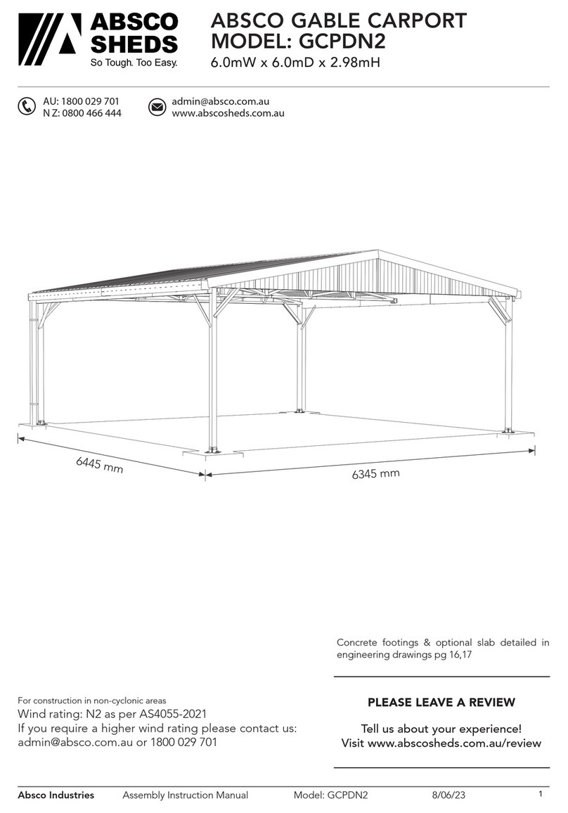
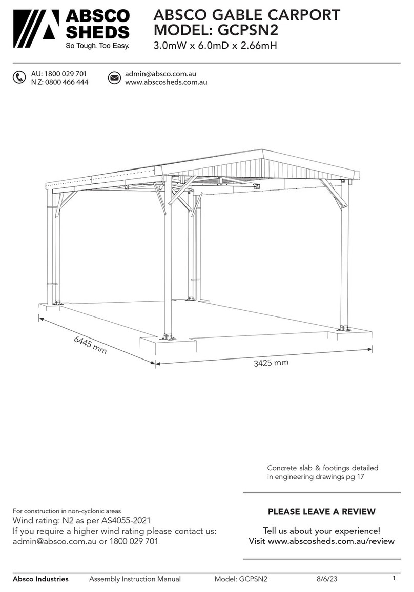
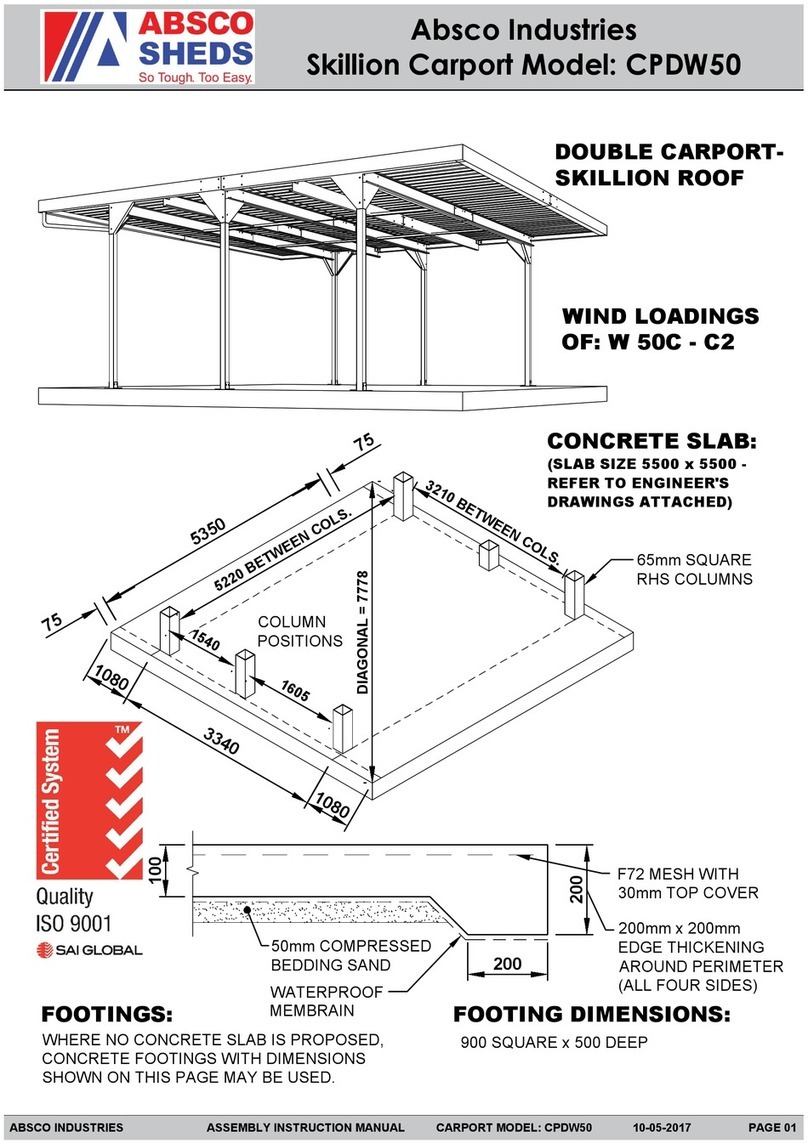
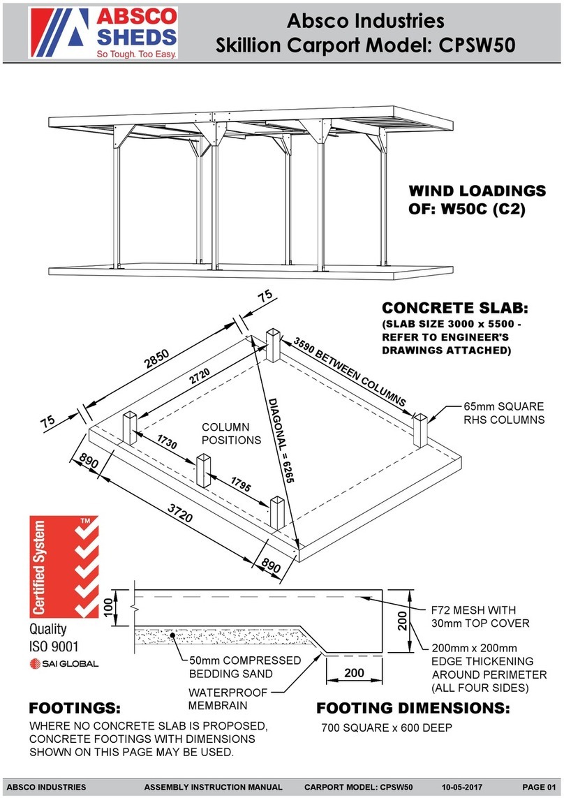
ABSCO SHEDS CPSN2 User manual

Absco Industries Assembly Instruction Manual
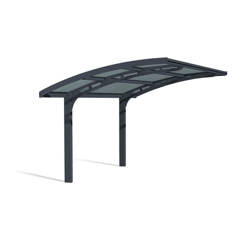
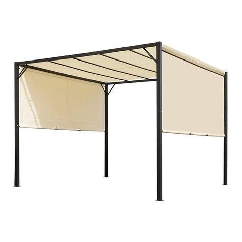
ABSCO SKILLION CARPORT
MODEL: CPSN2
3.00mW x 5.50mD x 2.37mH
Model: CPSN2 24/11/22 1
AU: 1800 029 701
N Z: 0800 466 444
www.abscosheds.com.au
For construction in non-cyclonic areas
Wind rating: N2 as per AS4055-2021
If you require a higher wind rating please contact
DOWNLOAD
OUR APP FOR
ASSEMBLY
VIDEOS
PLEASE LEAVE A REVIEW
Tell us about your experience!
Visit www.abscosheds.com.au/review
3000 mm
5500 mm
13551355 2790
2660 inside posts
2850
2720 inside
6265 diagonal
7575
Concrete slab & footings detailed
in engineering drawings pg 15,16

Absco Industries Assembly Instruction Manual
ABSCO SKILLION CARPORT
MODEL: CPSN2
3.00mW x 5.50mD x 2.37mH
Model: CPSN2 24/11/22 2
Site Preparation
• Local council approval must be obtained prior
to construction of the carport. Once you have
selected your site you will need to create
and lodge a site plan to your local council or
certifier. You will also have to attach a copy of
the engineering drawings at the back of these
instructions to your site plan.
• The site for the carport must be level, refer
to concrete and foundation notes on the
engineering drawing.
General Instructions
• Beforecommencinganyassembly,readthrough
these instructions and engineers drawings in
detail to gain a thorough understanding of
assembly methods and associated details.
• Some components have been pre-punched.
Some 10mm holes will still have to be drilled.
It may be easier to drill a small pilot hole first.
• Measure, and check off all components using
the parts lists on the following pages prior to
commencement. To prevent damage in transit,
some components may be packed inside
others, almost hidden. Carefully examine
inside each component to ensure that you
have located every item. If a discrepancy is
found, contact Absco Industries immediately.
Safety Notes
• The assembly of this product requires some
lifting of heavy objects. Two person lifts are
required.
• Some parts have sharp edges and/or corners.
The use of gloves and safety shoes is highly
recommended. Pay attention to where these
parts can be safely handled, and plan the
handling of these parts before working with
them.
• Drilling sheet metal produces small metal
shavings the use of safety glasses and the
periodic clearing of these shavings throughout
the build is recommended.
• Use the appropriate personal protective
equipment for any tool used during the
assembly.
Tools Required
• Electric drill with chuck
• 3 and 10 mm drill bits
• Hammer drill
• 10 mm masonry drill bit
• Mallet
• ‘G’ clamps
• Tape measure
• Socket set
• 17 mm spanner / shifter
• Spirit level
• Water proof sealant (silicone)
• 1.8m ladder
• PVC solvent welding cement.
BEFORE STARTING ASSEMBLY
Absco Industries Assembly Instruction Manual
ABSCO SKILLION CARPORT
MODEL: CPSN2
3.00mW x 5.50mD x 2.37mH
Model: CPSN2 24/11/22 3
COMPONENTS LIST - LARGE ITEMS
QTY COMPONENT
DESCRIPTION
PART
No. CHK QTY COMPONENT
DESCRIPTION
PART
No. CHK
8STEEL SHEET
2930 x 773 mm 152 2EDGE BEAM
3000 mm
ZACO
114
2
EDGE BEAM
LEFT NOTCH
2750 mm
ZACO
116 2
EDGE BEAM
RIGHT NOTCH
2750 mm
ZACO
115
1CROSS BEAM
2850 mm
ZACO
107 2CROSS BEAM
2720 mm
ZACO
231
2EDGE BEAM
SPLICE PLATE
ZACO
187 4
ANGLE BRACE
30 x 30
1395 mm
ZACO
121
2
COLUMN
BRACKET
LEFT
BKT
07 L 2
COLUMN
BRACKET
RIGHT
BKT
07 R
2
STEEL POST
65 x 65 RHS
2200 mm
COL
07 2
STEEL POST
65 x 65 RHS
2250 mm
COL
08
1
PVC
DOWNPIPE
1200 mm
RWG
13 1
PVC
DOWNPIPE
1880 mm
RWG
14
• Bend each column bracket along the slotted
centre line, holding at the points shown
• Apply sufficient pressure to form a 90 degree
angle along the bend line.
• Make sure the existing folded edges always
face inwards. The end result will give you two
“left hand” and “two right” hand brackets.
• NOTE: Please use 10mm drill bit and predrill
all holes before beginnings construction.
BEND COLUMN BRACKETS
90°
21
Repeat for all four BKT07

Absco Industries Assembly Instruction Manual
ABSCO SKILLION CARPORT
MODEL: CPSN2
3.00mW x 5.50mD x 2.37mH
Model: CPSN2 24/11/22 4
COMPONENTS LIST
QTY COMPONENT
DESCRIPTION
PART
No. CHK QTY COMPONENT
DESCRIPTION
PART
No. CHK
8BASE
BRACKET
BKT
02 12 STRAP ZACO
126
4JA2
BRACKET
ZACO
129 4JA1
BRACKET
ZACO
130
4JA3
BRACKET
ZACO
131 2JP PLATE ZACO
179
1
PVC
DOWNPIPE
45° FITTING
RWG
01 2
PVC
DOWNPIPE
90° FITTING
RWG
02
1
PVC
DOWNPIPE
DROP
RWG
17
FITTINGS PACK
1PHILLIPS HD
DRIVER BIT
FAST
038 16
BOLT
M10 x 80 mm
& NUT
FAST
022
72
BOLT
M10 x 20 mm
& NUT
FAST
018 180 M10 WASHER FAST
017
8DYNABOLT
10 x 50 mm
FAST
015 140 WAFER HD
TEK SCREW
FAST
014
120 NEOPRENE
WASHER
FAST
043

Absco Industries Assembly Instruction Manual
ABSCO SKILLION CARPORT
MODEL: CPSN2
3.00mW x 5.50mD x 2.37mH
Model: CPSN2 24/11/22 5
FRAME COMPONENT OVERVIEW
Roof sheet not shown for illustrative purposes.
Small components not called out, detail to follow.
Note: Not all components have the part number
printed on them. These can be identified by their
size and description in COMPONENT LIST.
Edge beams are also
guttering, diverting
water to rear.
Downpipe pg 14.
FRONT
2250 mm
2200 mm BKT
07 R
BKT
07 L
BKT
07 L
COL
07
COL
08
COL
08
BKT
07 R
COL
07
COL
07
ZACO
116
ZACO
115
ZACO
115
ZACO
116
ZACO
114
ZACO
114
ZACO
121
ZACO
121
ZACO
231
ZACO
231
ZACO
107

Absco Industries Assembly Instruction Manual
ABSCO SKILLION CARPORT
MODEL: CPSN2
3.00mW x 5.50mD x 2.37mH
Model: CPSN2 24/11/22 6
JOIN SPLICED BEAMS
Edge Beams
2x ZACO115
2x ZACO116
2x ZACO187
Edge & cross beams are
joined using their splice
plate, M10 x 20mm bolts,
nuts and washers as shown.
It’s best to have the nut on
the inside of the beam.
= 2x Side Beams
5500 mm long
ZACO
115
ZACO
116
ZACO
187
1 bolt fitted.
Each splice plate needs 8 bolts, 4 per end.
M10
WASHER
M10 x 20
BOLT
EDGE BEAM ZACO187
SPLICE PLATE
M10 NUT

Absco Industries Assembly Instruction Manual
ABSCO SKILLION CARPORT
MODEL: CPSN2
3.00mW x 5.50mD x 2.37mH
Model: CPSN2 24/11/22 7
EDGE BEAM ASSEMBLY
Secure the edge beams
together at each corner
using the joiner angles as
shown.
ZACO129
ZACO130
FRONT
Side Beams - 5500 mm long
End Beam - 3000 mm long
The joiner angles should be positioned on the
inside of the edge beams.
ZACO129 goes to the tall side and ZACO130 the
short side.
Hold with ‘G’ clamps and fastened with tek
screws from the outside of the edge beams.
Also fasten the bottom overlap with three tek
screws.
Seal all joints with water proof sealant such as
silicone as these beams are an internal gutter
system.
The overall dimension of the assembled edge
beams joined should be 3000 x 5490 mm
ZACO
114
ZACO
114

Absco Industries Assembly Instruction Manual
ABSCO SKILLION CARPORT
MODEL: CPSN2
3.00mW x 5.50mD x 2.37mH
Model: CPSN2 24/11/22 8
EDGE BEAM ASSEMBLY
Mark a line 1355 mm in from each end of the side
beams. These are the positions for locating the
column top brackets, BKT07.
To make rainwater flow to the downpipe at the
rear of the carport, the rear posts are 50mm
shorter than the front.
Mark these four hole positions of the BKT07 on
the beam and then drill 10 mm holes.
Don’t fasten these brackets yet, just make the
holes for now.
Therefore to keep the posts vertical, the BKT07
need to be inset 6 mm at their front-most edge
as shown below.
Make sure the side of the
BKT07 with these four holes
along the top edge are put
to the side beam.
1355 1355
BKT07 R
BKT07 L
6 mm 6 mm
Rear edge
flush with top
FRONT
FRONTREAR
Front edge
inset
Front edge
inset
Rear edge
flush with top

Absco Industries Assembly Instruction Manual
ABSCO SKILLION CARPORT
MODEL: CPSN2
3.00mW x 5.50mD x 2.37mH
Model: CPSN2 24/11/22 9
POST ASSEMBLY
POST HOLES
REAR LEFT FRONT LEFT
REAR RIGHT FRONT RIGHT
While they look similar and use the same
assembly methods, take care to use the correct
parts for each post.
The table lists which parts are needed for each
location.
Using the BKT07 as a template drill this 10mm
hole in the top of each post.
Make sure the top edges are flush before
marking & drilling.
This hole will be used as a pivot to stand the
structure later.
BKT07 R shown
Again using the BKT07 as a template drill these
four holes through both sides of the posts and
then fasten with four of the longer M10 x 80 mm
bolt and a nut with washers both sides.
2200 mm
Posts
2250 mm
Posts
BKT07 R
BKT07 L
BKT07 L
BKT07 R
LOCATION Post Bracket
Rear Left COL07 2200 mm BKT07 L
Right COL07 2200 mm BKT07 R
Front Left COL08 2250 mm BKT07 R
Right COL08 2250 mm BKT07 L

Absco Industries Assembly Instruction Manual
ABSCO SKILLION CARPORT
MODEL: CPSN2
3.00mW x 5.50mD x 2.37mH
Model: CPSN2 24/11/22 10
BASE BRACKETS
Using the BKT02 base brackets a
templates, drill four 10mm holes in the
bottom of the posts.
Make sure the brackets are orientated
with the single hole to the ground and
they’re on the front and rear faces of the
post.
Join the 2720 mm cross beam to the top brackets
of the front posts with four M10 x 20 mm bolt
and a nut with washers per sides.
Repeat this step for the rear posts too.
Fasten with four of the
M10 x 20 mm bolt and
a nut with washers both
sides.
Above shows the bolt
inserted from inside the
post. Use a spanner to
hold it in place when
tightening.
FITTING CROSS BEAMS

Absco Industries Assembly Instruction Manual
ABSCO SKILLION CARPORT
MODEL: CPSN2
3.00mW x 5.50mD x 2.37mH
Model: CPSN2 24/11/22 11
CENTRE CROSS BEAM
Mark the position for the centre-most cross beam
on the side beams.
Using the joiner angle ZACO131 as a template,
drill two 10mm holes in each end of the centre
cross beam, it’s the longest at 2850 mm.
Secure two ZACO131 to each end of the cross
beams with two M10 x 20 mm bolt and a nut with
washers both sides.
Make sure these are flush with the top face of the
cross beam to achieve a level surface to attach
the roof sheets to.
Position the ZACO179 joiner plate on the side
beam to the dimension shown above and drill
two 10mm holes in the beam, using it as the
template.
Move the ZACO179 inside the beam and to act
as a large washer for the bolts.
Secure cross beams to the side beams as shown
with two M10 x 20 mm bolt and a nut with
washers both sides.
ZACO131
Goes inside
Open side to rear
SIDE BEAM
CENTRE CROSS
BEAM 2850 mm
FRONTREAR
SIDE BEAM
2725 2725
CENTRE CROSS BEAM
40
5490
ZACO131
ZACO179

Absco Industries Assembly Instruction Manual
ABSCO SKILLION CARPORT
MODEL: CPSN2
3.00mW x 5.50mD x 2.37mH
Model: CPSN2 24/11/22 12
ATTACHING LEGS AND ERECTING
NOTE: Minimum two people required for these
step.
REAR POSTS
Referring back to page 9 locate one M10 x 20
mm bolt and a nut with washers both sides at
each end of the cross beam and post assembly
to the predrilled pivot holes.
Only finger tighten these for now to allow the
sections to move when lifted.
With one person holding each post begin to
carefully lift the roof structure.
Continue lifting until a second bolt can be
fastened to the top bracket and edge beam.
Secure all four M10 x 20mm bolts with a nut and
washer both sides.
FRONT POSTS
Repeat these steps for the other cross beam
assembly.
Now go around and full tighten all nut and bolt
connections, including splice plate connections.
Take care to check the bolts securing the base
brackets, as access can now be awkward.
ANCHOR
Using the dimensions on the front page secure
the frame to the concrete slab with the 50mm
dynabolts provided.

Absco Industries Assembly Instruction Manual
ABSCO SKILLION CARPORT
MODEL: CPSN2
3.00mW x 5.50mD x 2.37mH
Model: CPSN2 24/11/22 13
FRONT
BRACING
SHEETING
Equally space the angle roof braces (ZACO121)
as shown and secure to the underside of the
cross beams with two teks per connection.
It is critical that you begin at the
rear of the structure. Lay four
sheets left-to-right with an overlap
of one rib.
Align the short edge of the sheets
with the edge of the rear beam, as
shown in the detail view, and fasten
with a screw in every flat pan into
the framing.
Slip a neoprene washer onto the
tek before screwing for a water
tight connection.
The long edges of the sheeting
should be hard up against the
inside of the side edge beams.
secure along edges at 150mm
centres after all four rows of sheet
have been fixed.
Where the rear row of sheeting
overlaps the front row and a cross
beam fasten with a tek screw in
every second sheet pan.
With the front row of sheeting
make sure it is flush against the
inside front of the beam.
REAR FRONT
ONE
SCREW
AT
EVERY
PAN
ONE
SCREW
AT
EVERY SECOND
PAN
ONE
SCREW
AT
EVERY
PAN
ONE
SCREW
AT
EVERY
SECOND
PAN
ONE
SCREW
AT
EVERY PAN
Overlap roof sheets
and fasten with
screws.

Absco Industries Assembly Instruction Manual
ABSCO SKILLION CARPORT
MODEL: CPSN2
3.00mW x 5.50mD x 2.37mH
Model: CPSN2 24/11/22 14
DOWNPIPE
It can be fit to either end of the rear beam, make
a decision based on site specific factors.
Cut a round hole 51mm dia in one end of the
rear edge beam. The can be done by drilling a
series of 3mm holes and knocking it out or by
metal holesaw. It won’t be visible when finished.
Fit the galvanised gutter drop RWG17 from the
top down into the hole.
Drill two 3 mm holes through the underside of
the end beam and into the flange of the gutter
drop and then fasten using two pop rivets. Use
water proof sealant around the hole inside the
beam.
Join the top three pieces of the down pipe
assembly, RWG02 + RWG13 + RWG02 with PVC
solvent welding cement. Position over the gutter
drop and align with post.
Drill two 3 mm holes through both sides of the
PVC elbow and into the gutter drop and then
fasten with two tek screws.
Fit one end of downpipe RWG14 with the elbow
RWG01 at trim the other end to the desired
height. Fix with PVC solvent welding cement.
Bend two 270 x 25 mm flat strips ZACO126 to
shape around the downpipe and to the sides of
the post and fasten with tek screws.
Immediate maintenance required!
Clean down all roof and beam internal areas
of metal filings from drilling operations and
self drilling screws.
If not cleaned these will cause discolouration
and corrosion to roof sheets and galvanised
framing sections, see warranty for more details
RWG01
RWG02
RWG02
RWG14
1880 mm
ZACO126
RWG13
1200 mm
ZACO126
RWG17
RWG02
SIDE
BEAM
REAR
BEAM
Inset from
side beam
110 mm
110

1
1
2
2
3
3
4
4
5
5
6
6
A A
B B
C C
D D
1 OF1
CHECKED
06205-003-CP02 SKILLION CARPORTS
A3
TECH APPROVED
SCALE
SIZE
REV
SHEET
This document contains confidential and proprietary
information that cannot be reproduced or divulged, in whole or
in part, without written authorization from ABSCO INDUSTRIES
DRAWN SJC
-
SINGLE BAY
AS SHOWN 22-1
NOTE
D10 indicates D10075 Dynabolt, min embedment 55mm
*Column footing sizes where concrete slab is not provided.
If soil conditions prevent the specific footing depth being achieved increase
area of footing to maintain a volume of concrete equivalent to that
specified above.
This drawing is to be read
in conjunction with
06205-003-CP03
ROOF PLAN
1:25
TABLE A
GROUP B1
BMT
B2
BMT
B3
BMT
B4
BMT
COLUMN
BRACKET
BMT
COLUMN
WALL
THICKNESS
BOLT
GRADE
HD.
BOLTS FOOTING SIZE
1 1.0 0.8 1.0 1.0 1.2 1.6 8.8 8/D10 700 x 700 x 600*
N2 WIND CLASS ONLY
NOV 2022
SIDE ELEVATION
1:25
END ELEVATION
1:25
SECTION 1
Scale 1:25 -
B1
B2
B2
B3
B3
B4
3000
5500
1375 1375 1375 1375
1
A
CP03
5700
Varies
2250,2550,2850
Splice
connection
50 Dia. downpipe
strapped to column
100 thick slab
reinforced with
F72 fabric, 30 top
cover, see detail
sheet CP03
1°
B
CP03
Roof sheeting
30 x 30 x 1.0 Angles.
Connecto to bottom
flange of cross beams
with 2 teks each end.
columns 65x65 SHS,
wall thickness as per
schedule

1
1
2
2
3
3
4
4
5
5
6
6
A A
B B
C C
D D
1 OF1
CHECKED
06205-003-CP03 SKILLION CARPORTS - SINGLE & DOUBLE BAY
A3
TECH APPROVED
SCALE
SIZE
REV
SHEET
This document contains confidential and proprietary
information that cannot be reproduced or divulged, in whole or
in part, without written authorization from ABSCO INDUSTRIES
DRAWN SJC
12
--
TYPICAL STEEL WORK DETAILS
AS SHOWN 22-1
LOADINGS
L1 - These structures are classified as Class 10a of Importance
Level 2, and have been designed for the following wind loads to
AS1170.2 and the BCA - Volume 1: Refer 'Table A'.
L2 - The following structural pressure coefficients have been
used:
Empty under
- Windward = -0.3, +0.6
- Leeward = -0.4, +0.2
Blocked under
- Windward = -1.0, +0.4
- Leeward = -0.8, +0.4
L3 - Roof live loads to AS1170.1
UDL of 0.25 kPa. Point load of 1.1 kN to structural elements.
CONCRETE & FOUNDATIONS
C1 - Slab details are appropriate for sites classified as A, S, M &
H in accordance with AS2870.
C2 - Problem sites, extremely reactive sites and sites with
uncontrolled fill require individual assessment by an engineer.
C3 - If the structure is to be lined with fragile internal linings, is
to have fragile floor coverings (tiles) or to be used as
accommodation or office, the slab and footing system will need
to be modified to comply with the Australian Standards.
C4 - The foundations shall have a minimum allowable bearing
capacity of 75kPa.
C5 - Concrete F'c = 20 MPa minimum.
C6 - Slab to be poured on 50mm compacted sand bed and
waterproof membrane.
STEELWORK
S1 - Roof framing members shall be AZ150 material to the
Grades specified in AS 4600.
S2 - Roof, wall and door sheeting to be Grade G550 AZ150
Zincalume Hi-Ten with a BMT = 0.30 (Minimum)
S3 - Columns shall be Grade C450 Duragal.
S4 - Provide suitable corrosion protection to all ungalvanised
components e.g. zinc rich paint
FIXINGS
F1 - All screws to be No. 10 Wafer Teks with minimum edge
distance of 10mm and pitch of 15mm u.n.o.
F2 - Roof sheeting fixing to cross & edge beams:
(a) At edge and laps - 1 screw at every pan (i.e. 144 crs)
(b) Elsewhere - 1 screw every second pan (i.e. 288 crs).
Screws to roof sheeting to have neoprene washers.
F3 - Bolts to be M10 x 20 to the grade shown in the table.
F4 - All angle brackets & connector plates to be B.M.T. =
1.0mm u.n.o.
APPLICABLE S.A.A. CODES & STANDARDS
- AS 1170 Parts 1 &, 2 loading Codes.
- AS 4600 Cold Formed Steel Structures Code.
- AS 1562 Design and Installation of Sheet Roof & Wall
Cladding.
- AS 1111/1112 Metric Hexagon Commercial Bolts & Screws.
- AS 2312 Guide to the Protection of Iron & Steel.
- AS 4100 Steel Structures Code.
- AS 2870 Residential Slabs & Footings.
- AS 3600 Concrete Structures.
50 x 50 x 1.0 angle
x 45 long, 2 teks
each leg
50 x 50 x 1.0 angle
x 45 long, 2 teks
each leg
B1
B2
50
20
B1
100 x 50 x 1.0
plate
strengthener
Angle bracket 50
wide each side of
cross beam
fixed with a total
of 4-M10 bolts
60
100
20
CrossBeam
360
25
35
65 235
90
25
25
60
90
400
140
25 x 1.0 side & end
beams stiffeners at
cross beams & 1500
min. crs
1 tek each end
M10 bolts
typical
Column bracket
Column
40
140
75
55
11
11
38
138
73
53
10
140
40
40
1111
138
38
38
1010
1.0 BMT
1.2 BMT
COLUMN FOOTING / SLAB DETAILS
SCALE 1:10
DETAIL A
Scale 1:5 ## Scale 1:5 ##
DETAIL B
Scale 1:10 -
SECTION 1
BEAMS B1 & B2
'EDGE BEAM'
SPLICE PLATE FOR BEAMS
B1 & B2
SPLICE PLATE FOR BEAMS
B3 & B4
BEAMS B3 & B4
'CROSS BEAM'
TYPICAL MEMBER SECTIONS
SCALE 1:5
ROOF SHEETING SECTIONS
SCALE 1:5 SPLICE PLATE ELEVATION
(TYPICAL ALL TYPES)
SCALE 1:10
COLUMN FOOTING WHERE SLAB
NOT PROVIDED
COLUMN FOOTING WHERE SLAB
PROVIDED
365
35
65
60
180
140
55
25
90
60
400
Column
Column Bracket
M10 bolts
typical
Side Beam
End Span
Internal span
(i.e. Next column this way)
SECTION 2
Scale 1:10 -
144
22
44
18
0.3 BMT
600
138
25 25
50
250 250
88
25
25
M10 bolts
typical
Column
Hold down bolts, refer table.
Hold down bolts listed in
Table 1 may be replaced with
cast in bolts of the same dia.
with 50mm leg
D
B x W
Note:
Refer to table for
footing dimensions
SL72 mesh
30 top cover
65x65x5 hot dipped galv.
angle x 65 long
each side of column
2-M10 Bolts, washers
each side
Hold down bolts, refer table.
Hold down bolts listed in
Table 1 may be replaced with
cast in bolts of the same dia.
with 50mm leg
100
200Min.
200
50mm sand bedding &
waterproof membrane
Note:
Roof sheeting not
shown for clarity
CrossBeam
SideBeam
Column
Column bracket
DETAIL C
##
DIAGRAMMATIC COLUMN / BEAM
ELEVATION
SCALE 1:10
Refer to sheet 1 for
Detail locations
##
TABLE A
AS1170.2:2021
CLASSIFICATION
EQUIVALENT AS4055
CLASSIFICATION
EQUIVALENT AS1170:89
PERMISSIBLE STESS
CLASSIFICATION
(SUPERSEDED)
Group
Ultimate
Design
Wind
Pressure
(Pu)
Ultimate
Design
Wind
Speed
(Vsit,B)
Non-Cyclonic
regions A + B
Cyclonic
regions C
+ D
(m/s)
1 1.0 kPa 41 m/s N2 -W33N
N2 WIND CLASS ONLY
NOV 2022

Absco Industries Assembly Instruction Manual
ABSCO SKILLION CARPORT
MODEL: CPSN2
3.00mW x 5.50mD x 2.37mH
Model: CPSN2 24/11/22 17
Absco Sheds Storage Guidelines
• Absco Sheds are designed to be weatherproof for normal weather conditions. In the event of extreme
weather conditions such as heavy rain, combined with high wind gusts, the ridge capping, sheeting joins,
screw fixings etc., may exhibit minor deformations which may allow some water entry. These areas should be
checked regularly to ensure that maximum strength and protection is maintained.
• Other weather conditions such as extreme heat and extreme cold, moist or dry air can influence the effects
of concrete floor moisture and/or condensation on the underside of the roof sheets.
• Absco Sheds and storage units are primarily used for storage of garden equipment such as lawnmowers,
wheelbarrows, garden tools etc. Storage items that might be adversely affected by any of the above conditions
may require additional protection such as being sealed or covered by plastic sheets and/or stacked above
the concrete floor on timber slats.
• Waterproof sealants may be used to offer further protection where required around joins and screw fixings,
as can rubber door seals and other products which are available from most hardware outlets.
• Placement of waterproof sealants (silicone) between the base of the shed and concrete slab is not
recommended, as this process can have a reverse effect, preventing excess water from escaping, resulting
with water accumulating and being trapped inside the shed.
• Absco accepts no responsibility for water entry, floor moisture, condensation or the condition of the Contents
inside your Absco steel building arising from any of the pre-mentioned weather conditions.
6-12 Activity St, Acacia Ridge QLD 4110
PO Box 119, Acacia Ridge QLD 4110
AU: 1800 029 701
N Z: 0800 466 444
www.abscosheds.com.au

Lifetime Warranty Statement
This warranty against defects is given by:
Absco Industries (ABN: 77 869 708 678)
Address: PO Box 119 Acacia Ridge QLD 4110
Ph: 1800 029 701
Fax: 07 3344 1191
Email: [email protected]
Date of issue: 18 November 2022
Details of Manufacturer’s Warranty
This product comes with a Lifetime structural warranty from the date of purchase. This warranty also
applies where there are missing or damaged parts identified in the parts list referred to in the instruction
kit within the product packaging.
Please ensure that you keep this warranty form in a safe place along with your proof of purchase. You can
register your warranty online http://abscosheds.com.au/warranty-details/ or complete the form on the
back of this document and mail it back to Absco, along with a copy of your proof of purchase.
The benefits of this warranty are in addition to your rights under the Australian Consumer Law (ACL) and
in particular, the guarantees implied under the ACL and any other rights and remedies of the consumer
under a similar law in relation to the goods and services to which this warranty relates.
Process of claiming warranty:
To make a claim under the warranty within the warranty period, you will need to contact the manufacturer
directly by phone or email:
Contact Number: 1800 029 701
You will be required to produce proof of purchase (this is at discretion of the manufacturer) at the time of
the claim.
The manufacturer bears the cost of replacing the products or spare parts or repairing the products and
reasonable direct expenses of claiming under this warranty:
Where parts are replaced, the manufacturer will bear the cost of sending the spare part and will endeavour
to deliver it to the customer’s nearest reseller within 20 working days for the customer to pick up. At such
time the customer may be required to return the alleged faulty parts.
Where assessment is required in case of replacing or repairing the product, the manufacturer will appoint
an assessor within 10 working days to identify the alleged defect. The manufacturer will bear the repair
costs by appointing a local tradesman. The manufacturer may choose to replace the product if the repair or
the cost of repair is not feasible. The replacement product will be available for collection from the nearest
reseller within 20 working days. The customer will bear the cost of assembly for the replacement product.
1

IMPORTANT
1. Manufacturer’s Disclosure
This warranty against defects shall not apply in the following situations:
A) Where the product is not assembled in accordance with the instructions provided in the product kit;
B) Where the product is used to store corrosive materials such as fertilizer, chlorine etc;
C) The warranty does NOT cover damage caused by storms, wind, rain, snow or poor foundations;
D) This warranty does not apply to surface deterioration of panels caused by ‘Swarf’ (Tiny particles of
steel debris left from cutting, grinding or drilling operations) that has not been removed after building
construction.
E) This warranty does not apply to ABSCO products installed in severe coastal, Industrial, or other highly
corrosive environments. The warranty does apply to fasteners (screws, nuts, bolts, rivets, hasps, or
bolts).
2. Notes
This product is weatherproof to a certain level; however driving windy rain may cause the product to leak.
Condensation may also occur in some weather conditions such as extreme heat or cold. The product
should only be used for storing items such as gardening equipment and should not be used for articles
that may be prone to damage if they come into contact with moisture.
3. Major Defects
If the manufacturer is satisfied that the defect is a major defect, the purchase price may be refunded in lieu
of providing a replacement product or repairing the product.
This warranty is provided in addition to other rights and remedies you have under law: Our goods come
with guarantees which cannot be excluded under the Australian Consumer Law. You are entitled to
replacement or refund for a major failure and to compensation for other reasonably foreseeable loss or
damage. You are also entitled to have the goods repaired or replaced if the goods fail to be of acceptable
quality and the failure does not amount to a major failure.
If you do not wish to register your warranty online, complete the below form and email, fax or
post this form back to Absco, along with a copy of your proof of purchase.
NAME:
STREET ADDRESS: POSTAL / ZIP CODE:
STATE / CITY / PROVINCE / REGION:
COUNTRY:
SHED TYPE/CODE:
ORDER NO:
DATE OF PURCHASE:
EMAIL ADDRESS:
DATE REGISTERED:
2
Table of contents
Other ABSCO SHEDS Tent manuals

ABSCO SHEDS
ABSCO SHEDS RG37601N2 User manual

ABSCO SHEDS
ABSCO SHEDS 3052UTK Installation guide

ABSCO SHEDS
ABSCO SHEDS GCPSN2 User manual

ABSCO SHEDS
ABSCO SHEDS CPSW50 Installation guide

ABSCO SHEDS
ABSCO SHEDS 3060HGK Installation guide

ABSCO SHEDS
ABSCO SHEDS GCPDN2 User manual

ABSCO SHEDS
ABSCO SHEDS CG34552N2 User manual

ABSCO SHEDS
ABSCO SHEDS CPSW33 User manual

ABSCO SHEDS
ABSCO SHEDS CG56552N2 Installation guide

ABSCO SHEDS
ABSCO SHEDS CPDW50 Installation guide