manuals.online logo
Brands
  1. Home
  2. •
  3. Brands
  4. •
  5. Absolute Process Instruments
  6. •
  7. Security System
  8. •
  9. Absolute Process Instruments Cecomp F16ADA User manual

Absolute Process Instruments Cecomp F16ADA User manual

Programmable Pressure Alarms F16ADA
BSOLUTE ROCESS NSTRUMENTS, Inc.
api-usa.com
201
1220 American Way Libertyville, IL 60048
Phone: 800-942-0315 Fax: 800-949-7502
© 02-09
Ranges and Resolution
abs: Absolute reference (atmospheric pressure to zero at full vacuum)
vac: Vacuum gauge, minus sign not used unless specified
Resolution is fixed as indicated in table
Contact factory for engineering units not listed
Accuracy
Includes linearity, hysteresis, repeatability
Standard: ±0.25% of full scale ±1 least significant digit
Optional: -HA ±0.1% FS ±1LSD (most ranges)
CD Factory 5-point calibration data
NC NIST traceable test report and 5-point calibration data
Display
4 readings per second nominal display update rate
41/2digit LCD, 0.5" H main display
5 character 0.25" H alphanumeric lower display for units, functions, and setup
BL models: Red LED backlight on whenever gauge is on.
LCD Alarm 1 and Alarm 2 indicators and bi-color (red/green) LEDs on front panel
Controls and Functions
SEL Select and display alarm trip points
TEST Alarm acknowledge, or toggle alarm states when in test mode
▲▲Increase alarm setpoint when in setpoint adjust mode
▼▼Decrease alarm setpoint when in setpoint adjust mode
Calibration
User settable passcode required to enter calibration mode
All pressure and absolute models: zero, midpoint, span
All vacuum models: –span, –midpoint, zero
Vacuum/pressure models: –span, zero, +midpoint, +span
±15 psi models: –span, –midpoint, zero, +midpoint, +span
Alarm Outputs and Deadband
Dual form C (SPDT) relay contacts; 1A/24VDC, 0.5A/115VAC, non-inductive
3 ft long 6-conductor 22 AWG cable with stripped and tinned wire ends
Available configurations: HI/LO, HI/HI, LO/LO, normal or reverse acting
120 milliseconds typical response time
Hysteresis factory set at 1% of of full scale
Power
Gauge is on whenever power is applied. Designed for continuous operation.
Any AC source of 8 to 24 VAC 50/60 Hz or any DC source of 9 to 32 VDC
1.0 watt maximum power consumption
3 ft long 2-conductor 22 AWG power cable with stripped and tinned wire ends
Order optional WMPSK 12 VDC wall mount power supply kit to operate on 115 VAC
Environmental
Storage temperature: –40 to 203°F (–40 to 95°C)
Operating temperature: –4 to 185°F (–20 to 85°C)
Compensated temperature: 32 to 158°F (0 to 70°C)
●●Dual SPDT Alarms with Programmable Setpoints
●●NEMA 4X and Display Backlighting Optional
●●Bi-Color Red/Green Alarm LEDs
●●Alarm Test Function
Size
F16ADA: 3.38" W x 2.88" H x 1.65" D housing
F16ADAN: 3.5" W x 3.0" H x 2.0" D housing
Add approximately 0.75" to height for pressure fitting
Add approximately 1" to depth for strain relief and wire clearance
Weight
Gauge: 9 ounces (approx.)
Shipping wt.: 1 pound (approx.)
Housing
F16ADA: Extruded aluminum case, light gray epoxy powder coated, black ABS/ poly-
carbonate bezel (gray aluminum bezel optional), front and rear gaskets,
black/gold polycarbonate label
F16ADAN: Light gray ABS/polycarbonate NEMA 4X case, rear gasket, black/gold poly-
carbonate label
Pressure/Vacuum Connection Size and Material
1/4 NPT male
All wetted parts are 316 stainless steel
Overpressure
3000 psig range and metric equivalents: 5000 psig
5000 psig range and metric equivalents: 7500 psig
All others 2 times sensor pressure
112.5% out-of-range display: I – – – or I –.–.–.– depending on model
Burst Pressure
4 times sensor pressure rating, or 10,000 psi, whichever is less
Standard F16ADA range units ref - alarm
Backlit F16ADABL range units ref - alarm
NEMA 4X F16ADAN range units ref - alarm
Backlit + NEMA 4X F16ADANBL range units ref - alarm
Pressure/Vacuum Range
Units
G=Gauge, A=Absolute, VAC=Vacuum
Alarm Options
1N = Hi/Lo Normal action (Std) 1R = Hi/Lo Reverse action
2N = Hi/Hi Normal action 2R = Hi/Hi Reverse action
3N = Lo/Lo Normal action 3R = Lo/Lo Reverse action
Example: F16ADABL500PSIG-1N
F16ADA with BL display backlighting, 500 psig, HI/LO normal action alarms
F16ADA
Pressure
Models and Options
cecomp.com
–30.0 inHg/15.0 psig 200.0 inHg abs 1600 mmHg 20.00 bar 2100 g/cm2
–30.0 inHg/100.0 psig 200.0 inHg 3200 mmHg 35.00 bar 1.000 kg/cm2abs
–30.0 inHg/200.0 psig 50.00 oz/in2760.0 torr abs 70.00 bar 1.000 kg/cm2vac
3.000 psig 80.0 oz/in21600 torr abs 140.0 bar ±1.000 kg/cm2
5.000 psig 240.0 oz/in2abs 2100 mmH2O200.0 bar 1.000 kg/cm2
15.00 psi abs 240.0 oz/in2vac 3500 mmH2O350.0 bar 2.000 kg/cm2abs
15.00 psig vac ±240.0 oz/in2210.0 cmH2O20.00 kPa 2.000 kg/cm2
±15.00 psig 240.0 oz/in2350.0 cmH2O35.00 kPa 4.000 kg/cm2
15.00 psig 85.0 inH2O1000 cmH2O100.0 kPa abs 7.000 kg/cm2abs
30.00 psi abs 140.0 inH2O2100 cmH2O100.0 kPa vac 7.000 kg/cm2
30.00 psig 400.0 inH2O abs 200.0 mbar ±100.0 kPa 14.00 kg/cm2
60.00 psig 400.0 inH2O vac 350.0 mbar 100.0 kPa 20.00 kg/cm2
100.0 psi abs ±400 inH2O1000 mbar abs 200.0 kPa abs 35.00 kg/cm2
100.0 psig 400.0 inH2O1000 mbar vac 200.0 kPa 70.00 kg/cm2
200.0 psig 850 inH2O abs ±1000 mbar 400.0 kPa 140.0 kg/cm2
300.0 psig 850 inH2O1000 mbar 700.0 kPa abs 200.0 kg/cm2
500.0 psig 7.000 ftH2O2000 mbar abs –100 to 700 kPa 350.0 kg/cm2
1000 psig 12.00 ftH2O2000 mbar 700.0 kPa 1.000 atm abs
2000 psig 35.00 ftH2O4000 mbar 1500 kPa ±1.000 atm
3000 psig 70.00 ftH2O1.000 bar abs 2000 kPa 1.000 atm
5000 psig 140.0 ftH2O1.000 bar vac 3500 kPa 2.000 atm
6.000 inHg 230.0 ftH2O±1.000 bar 7000 kPa 4.000 atm
10.00 inHg 480.0 ftH2O1.000 bar 3.500 MPa 7.000 atm
30.00 inHg abs 150.0 mmHg 2.000 bar abs 7.000 MPa 14.00 atm
30.00 inHg vac 260.0 mmHg 2.000 bar 14.00 MPa 20.00 atm
±30.00 inHg 760.0 mmHg abs 4.000 bar 20.00 MPa 35.00 atm
30.00 inHg 760.0 mmHg vac 7.000 bar abs 35.00 MPa 70.00 atm
60.00 inHg abs ±760 mmHg –1.00 to 7.00 bar 1000 g/cm2abs 135.0 atm
60.00 inHg 760.0 mmHg 7.000 bar 1000 g/cm2200.0 atm
120.0 inHg 1600 mmHg abs 14.00 bar 2100 g/cm2abs 340.0 atm
Unit Abbreviations
psi = PSI
inHg = INHG
oz/in2= ZIN
inH2O = INH2O
ftH2O = FTH2O
mmHg = MMHG
torr = TORR
mmH2O = MMH2O
kg/cm2= KGCM
g/cm2= GCM
kPa = KPA
MPa = MPA
mbar = MBAR
bar = BAR
cmH2O = CMH2O
atm = ATM
F16ADAN
202
F16ADA Series Instructions
© 02-09
INSTALLATION AND PRECAUTIONS
Install or remove gauge using wrench on hex fitting only. Do not turn using housing or any
other part of the gauge. Use fittings appropriate for the pressure range of the gauge. Do
not apply vacuum to gauges not designed for vacuum operation. Due to the hardness of
316 stainless steel, it is recommended that a thread sealant be used to ensure leak-free
operation. NEVER insert objects into the gauge port or blow out with compressed air.
Permanent damage not covered by warranty will result to the sensor.
POWER CONNECTIONS
NEVER connect the gauge power wires directly to 115 VAC or permanent damage not cov-
ered by warranty will result! The F16ADA sereis can be powered by an AC source of 8 to
24 VAC 50/60 Hz or DC source: 9 to 32 VDC
Connect power to the smaller two-conductor cable with one RED and one BLACK lead. The
gauge will operate on either AC or DC power, so there is no need to observe polarity.
Operation with less than 8 VAC RMS if AC, or 9 VDC may cause erratic or erroneous read-
ings or alarm operation.
The gauge is powered on whenever a supply voltage is applied. During power-up, the dis-
play briefly indicates the rated full-scale pressure with “FS” indicated on the lower display.
This is followed by a test of all display segments. The gauge then proceeds to the normal
operating mode. The gauge may be left on at all times or as required. Alarm setpoints, the
calibration passcode, and calibration information are stored in non-volatile memory.
ALARM OUTPUT WIRING
The 6-conductor cable is for the 2 SPDT relay contacts.
Contact 1 Normally Closed (NC) BLACK
Contact 1 Common (C) RED
Contact 1 Normally Open (NO) WHITE
Contact 2 Normally Closed (NC) GREEN
Contact 2 Common (C) BROWN
Contact 2 Normally Open (NO) BLUE
Contact Rating and Protection - The contacts of the
alarm relays are rated at 1A/24VDC or 0.5A/115VAC. Using mechanical relay contacts
above their rating, or with large inductive loads, will shorten their useful life. In circuits other
than low-level switching or pilot duty, the user should consider whether external contact
protection such as snubber networks or arc suppression networks are required to protect
the contacts. No internal fusing is included in the alarm contact circuits. The alarm outputs
should be externally fused by the user in applications where good design practice dictates.
NORMAL OPERATION
In normal operation the display indicates the applied pressure with engineering units dis-
played on the character segments. A green LED indicates a normal or no-alarm condition.
If any alarm condition is present, the relevant LCD alarm icon will be shown on the display
and the corresponding bi-color LED will be red and blink at a slow rate until the alarm is
acknowledged or the alarm condition clears. Press and release the TEST button to
acknowledge an alarm condition.
The alarm trip point values are displayed by pressing the SEL (select) button. Press once
to show Trip 1 and press again to show Trip 2. Pressing the SEL button again returns
the gauge to the normal display.
If a particular setpoint is configured as a HI alarm, the gauge will provide a RED alarm indi-
cation when the system pressure exceeds the setpoint. If a particular setpoint is configured
as a LO alarm, the gauge will provide a RED alarm indication when the system pressure
falls below the setpoint. Alarm configurations are set at the factory and may be ordered as
HI/LO, HI/HI, or LO/LO configurations.
USING THE TEST FUNCTION
For system setup, testing, and troubleshooting, the test function can be used to toggle the
state of the alarm relays. This allows them to be switched to their opposite state on demand
without the need to vary the system pressure to test devices connected to the alarms.
While in the normal operating mode, press and hold the TEST button and press the SEL
button. Release both buttons when the display indicates – – – – .
While in the Test Alarms mode the display will indicate the applied pressure with engineer-
ing units blinking at a slow rate.
To invert the alarm states, press the TEST button. As long as the TEST button is held
pressed, the alarm indicators and the alarm relays will be opposite to what they would nor-
mally be for the applied pressure displayed.
When the TEST button is released, the alarm indicators will return to their normal operat-
ing state corresponding to the applied pressure being displayed. To exit the Test Alarms
mode and return to normal operation, press and release the SEL button.
ALARM TYPES: NORMAL VS. REVERSE ACTION
With Normal configuration (alarm options 1N, 2N, or 3N), the alarm output relays will be
CLOSED (relay energized) for a non-alarm condition and OPEN (relay not energized) for
an alarm condition. This produces an alarm condition if the gauge loses power.
Therefore, with the Normal configuration, in a green or non-alarm condition the relay will be
energized so that continuity can be expected between the common and normally open
leads. In a red or alarm condition, the relay will be open (not energized), so that continuity
can be expected between the common and normally closed leads.
If no alarm condition is required when the gauge power is off specify Reverse action (alarm
options 1R, 2R, or 3R). In this case, the relay will be open (not energized) in the non-alarm
condition and closed for the alarm condition. In this case, continuity can be expected from
common to normally closed in the green (non-alarm) condition and from common to nor-
mally open in the red (alarm) condition.
DEADBAND
The alarm circuit setpoints have built-in deadbands, also known as hysteresis, of 1% of
span as standard. This is a fixed value set at the factory. This means, for example, the
deadband is approximately 1 psi in a 0 to 100 psi gauge.
This deadband serves to eliminate output oscillation or “chatter” in the process due to minor
fluctuations in pressure. If, for example, the system pressure in a 0-100 psi system is 40.0
psi, and Setpoint 1 is set to 50.0 psi (HI alarm), the alarm indication will trip if the pressure
exceeds 50.0 psi. After the HI alarm has tripped, pressing the SP1 button will show that the
alarm indication will “release” at 1 psi lower (approximately 49 psi).
ALARM SETPOINT ADJUSTMENTS
Setpoint is defined as the value of applied pressure that will result in a change of state only
from a normal to an alarm condition. Trip Point is defined as the value of applied pressure
that will result in a change of state of alarm condition, and includes the effect of deadband
when returning from an alarm to a normal condition.
1. Make sure the gauge is in the normal operating mode. To adjust setpoint 1 press the
SEL (select) button once to show TRIP1 on the lower display.
2. While pressing and holding the TEST button, press the SEL button. Release both but-
tons when the display indicates – – – – .
3. The display will indicate trip point 1 with TRIP1 blinking on the lower display.
4. To adjust the setpoint 1 value, press and hold the TEST button. The display will indi-
cate setpoint 1 with SP1 on the character segments.
5. Use the ▲and ▼buttons to adjust the setpoint to the desired value. The setpoint value
is stored when the TEST button is released. The LEDs will turn off and the gauge will
not respond to changes in applied pressure while the TEST button is held pressed. The
alarm relays and LCD indicators will maintain their prior states until the TEST button is
released.
6. To exit the setpoint adjust mode and return to normal operation, press and release the
SEL button.
7. Setpoint 2 is adjusted in the same manner. Press the SEL button twice to show TRIP2
on the lower display and follow the same procedure as setpoint 1.
CALIBRATION
The gauge is calibrated at the factory using equipment traceable to NIST. There is no need
to calibrate the gauge before putting it in service.
A user-settable passcode is required to access the gauge calibration functions. Passcode
information and gauge calibration instructions can be downloaded from www.cecomp.com
or requested by calling us at 800-942-0315. Gauges may be also returned to Cecomp for
factory certified or NIST traceable calibration.
DIMENSIONS
1/4" NPT
Cecomp Electronics / Made in USA
2.88"
3.38"
0.75" 0.75"
1.65"
Turn at
hex
fitting only
Two 3 ft long,
22 AWG cables, 2-
conductor power,
6 conductor alarm
SEL TEST ▼
▲
XXXXX
8
8
8
8
82
ALARM 1 ALARM 2
BSOLUTE ROCESS NSTRUMENTS, Inc.
1220 American Way Libertyville, IL 60048
Phone: 800-942-0315 Fax: 800-949-7502
For latest product information or to contact
your local representative visit api-usa.com
Cecomp maintains a constant effort to upgrade and improve its products. Specifications
are subject to change without notice. Consult factory for your specific requirements.
Pressure
1/4" NPT
3.0"
3.5"
0.75"
2.0"
F16ADAN
XXXXX
8
8
8
8
82
Two 3 ft long,
22 AWG cables, 2-
conductor power,
6 conductor alarm
0.75"
Turn at
hex fitting
only!
Cecomp Electronics / Made in USA
SEL TEST ▼
▲
F16ADA
NC 1
C1
NO 1
NC 2
C2
NO 2
NC 1
C1
NO 1
NC 2
C2
NO 2
This manual suits for next models

3

Other Absolute Process Instruments Security System manuals

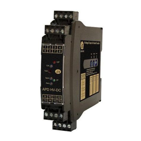
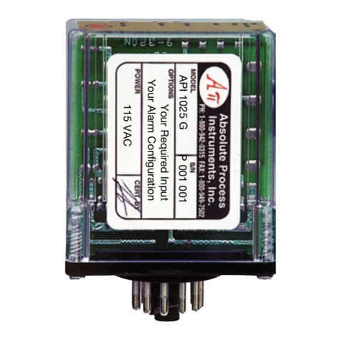
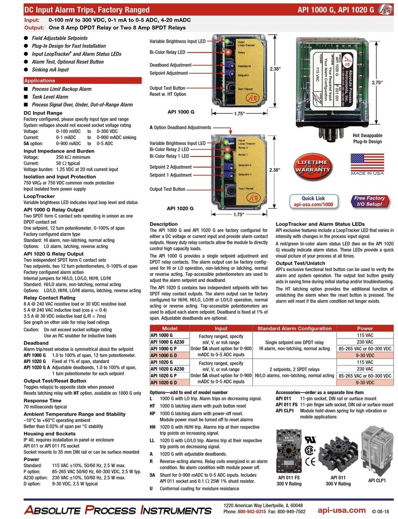
Absolute Process Instruments API 1080 G User manual

Absolute Process Instruments

Absolute Process Instruments API 1080 G User manual

Absolute Process Instruments APD 1431 User manual

Absolute Process Instruments

Absolute Process Instruments APD 1431 User manual

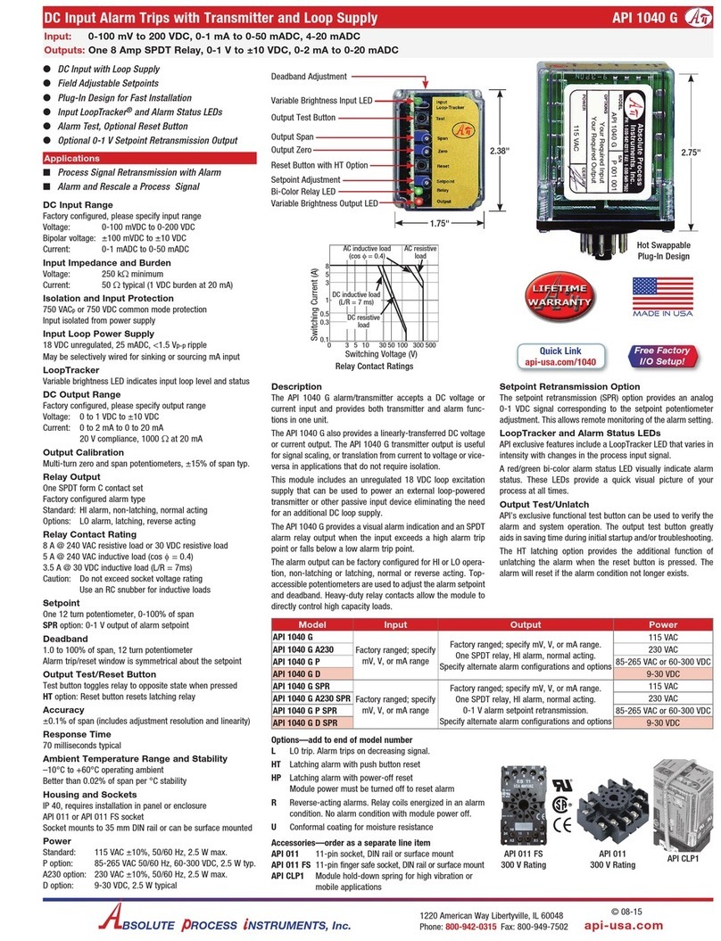
Absolute Process Instruments API 1040 G Series User manual

Absolute Process Instruments

Absolute Process Instruments API 1040 G Series User manual

Absolute Process Instruments APD 1400 User manual

Absolute Process Instruments

Absolute Process Instruments APD 1400 User manual

Absolute Process Instruments APD 1200 User manual

Absolute Process Instruments

Absolute Process Instruments APD 1200 User manual

Absolute Process Instruments API 1000 G User manual

Absolute Process Instruments

Absolute Process Instruments API 1000 G User manual

Absolute Process Instruments API 1005 G User manual

Absolute Process Instruments

Absolute Process Instruments API 1005 G User manual

Popular Security System manuals by other brands

GE 45413 user manual

GE

GE 45413 user manual

Stahl YA60 Series operating instructions

Stahl

Stahl YA60 Series operating instructions

Melaleuca Home Security quick start guide

Melaleuca

Melaleuca Home Security quick start guide

Stark ST-6108W operating manual

Stark

Stark ST-6108W operating manual

Halton Safe Management 2.0 Installation, commissioning, operating, and maintenance guide

Halton

Halton Safe Management 2.0 Installation, commissioning, operating, and maintenance guide

SAFE-T-ALERT 85-741 user manual

SAFE-T-ALERT

SAFE-T-ALERT 85-741 user manual

ELRO PK4910 instruction manual

ELRO

ELRO PK4910 instruction manual

Patlite NE-USB Series instruction manual

Patlite

Patlite NE-USB Series instruction manual

GE 60-806-95R-16Z - Security Concord Express System Control... installation instructions

GE

GE 60-806-95R-16Z - Security Concord Express System Control... installation instructions

Interlogix NX-595E user manual

Interlogix

Interlogix NX-595E user manual

Risco LightSYS user manual

Risco

Risco LightSYS user manual

Thales V6000 Installation and configuration guide

Thales

Thales V6000 Installation and configuration guide

Esse-ti HELPY COMPACT-Q quick guide

Esse-ti

Esse-ti HELPY COMPACT-Q quick guide

GE TX-7201-05-1 quick start guide

GE

GE TX-7201-05-1 quick start guide

ADEMCO VIA-30PSE installation instructions

ADEMCO

ADEMCO VIA-30PSE installation instructions

HAI 69A00-1 installation instructions

HAI

HAI 69A00-1 installation instructions

Kidde 8LLCO user manual

Kidde

Kidde 8LLCO user manual

Teldat VisorALARM PLUS 2U operating instructions

Teldat

Teldat VisorALARM PLUS 2U operating instructions

manuals.online logo
manuals.online logoBrands
  • About & Mission
  • Contact us
  • Privacy Policy
  • Terms and Conditions

Copyright 2025 Manuals.Online. All Rights Reserved.