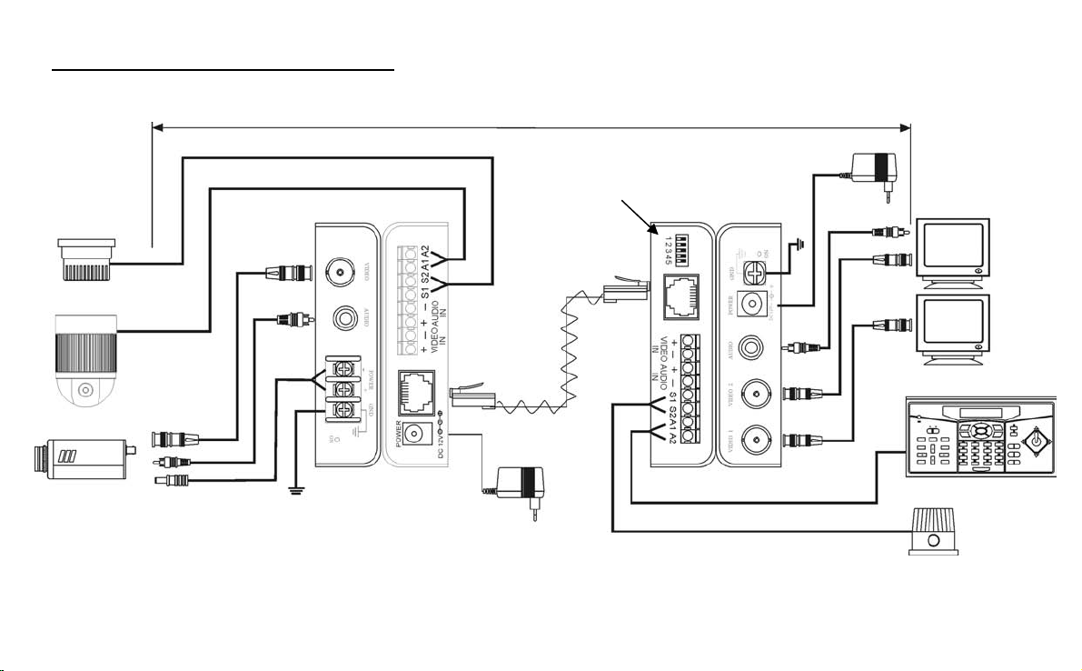
4. Anschlußplan TV8720 (Fortsetzung)
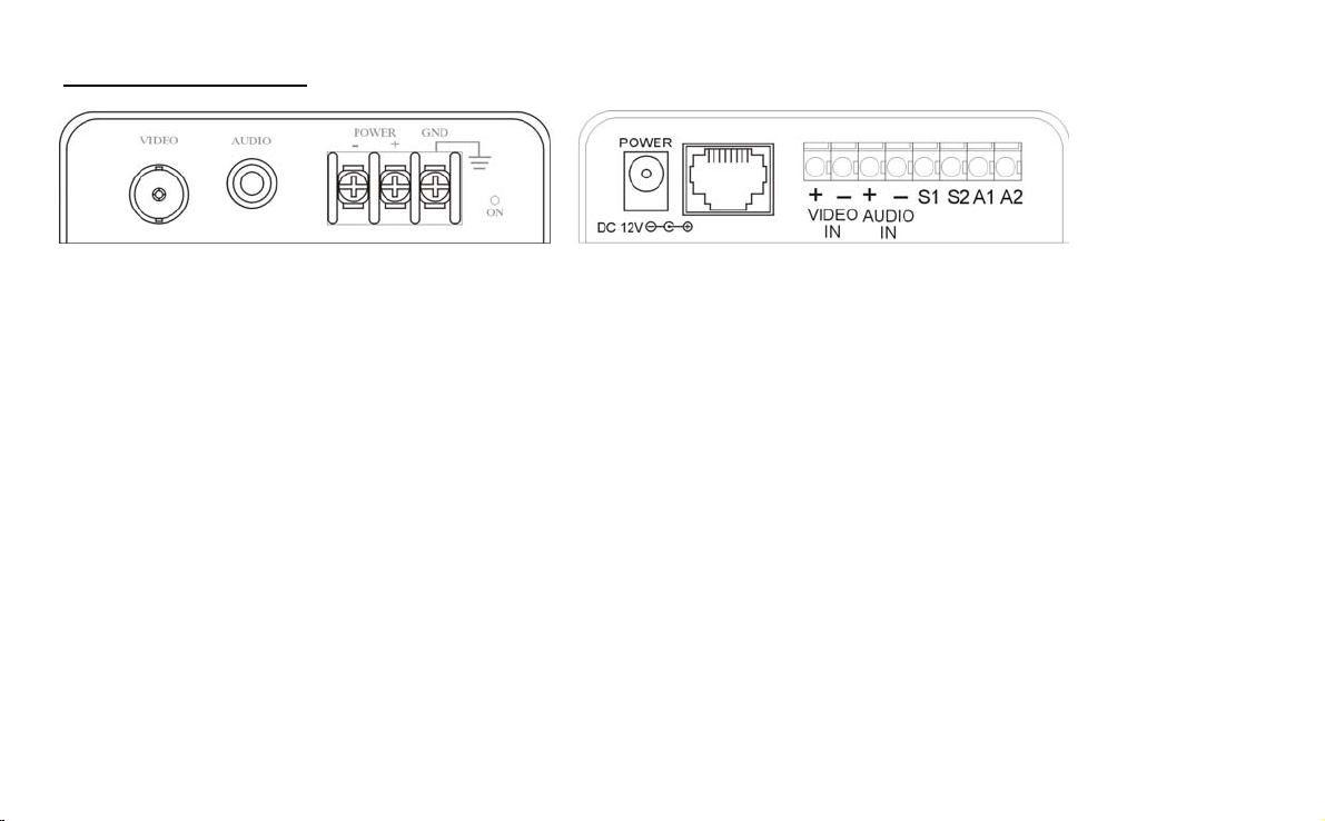
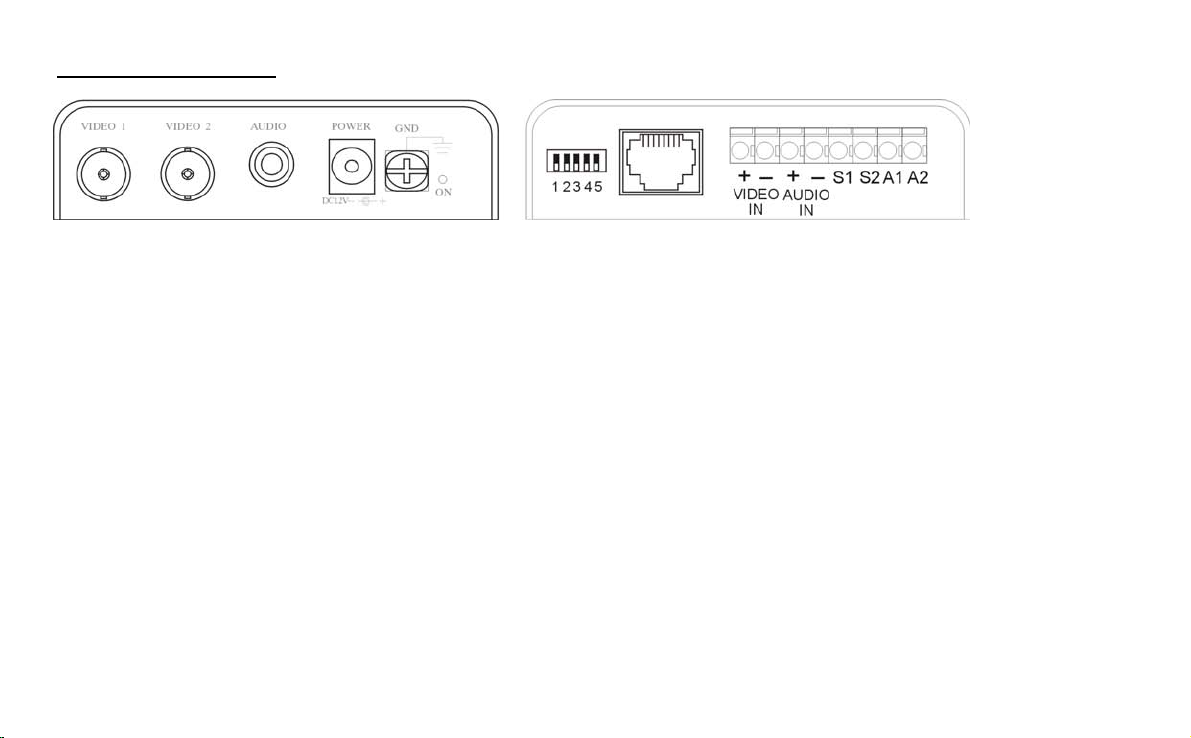
Empfängermodul Frontseite Empfängermodul Rückseite
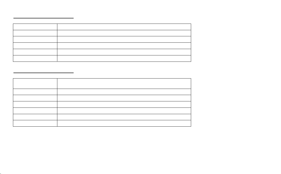
Anschlüsse am Empfängermodul –
Frontseite:
Video 1 – Composite (FBAS)-Videoausgang 1
Video 2 – Composite (FBAS)-Videoausgang 2
Audio – Audioausgang
Power – 12VDC Eingang für Netzteil
GND – Gehäusemasse
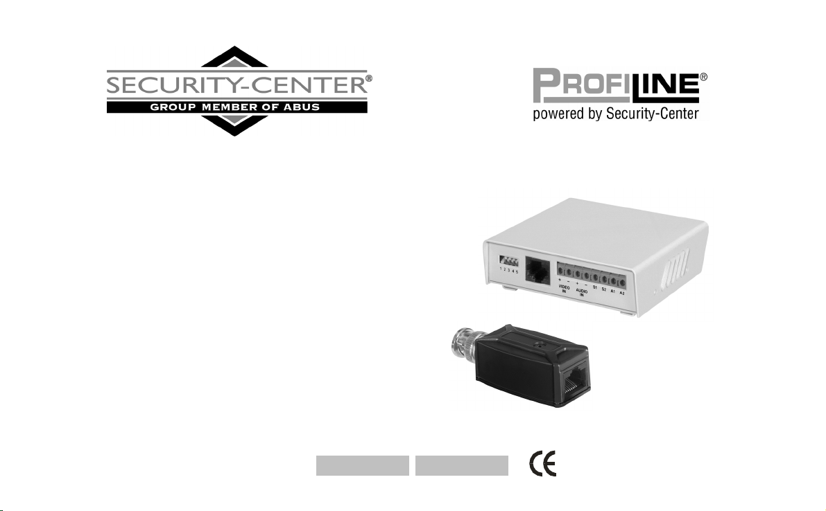
Anschlüsse am Empfängermodul –
Rückseite:
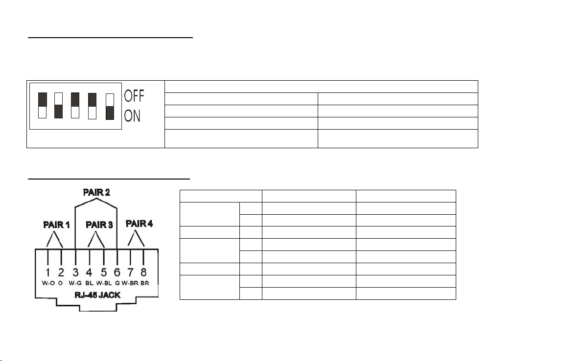
12345 – Reichweiteneinstellung
RJ11-Steckbuchse – Eingang für Twisted Pair CAT 5 Kabel
Video IN – Klemmanschluß für Twisted-Pair-Übertragung (statt RJ45)
Audio IN – Klemmanschluß für Twisted-Pair-Übertragung (statt RJ45)
Power – 12VDC Eingang für Netzteil
S1/S2 – Ausgang für Alarmkontakt (NO)
A1/A2 – Eingang für Datenleitung (RS485)
RJ45 -Steckbuchse – Eingang für Twisted Pair CAT 5 Kabel
Die maximale Distanz zwischen einem Sende- und Empfangsmodul darf (je nach Einstellung) 2.400m nicht überschreiten. Achten Sie darauf,
daß Sie die Verbindungsleitung möglichst nicht in der Nähe von spannungsführenden Leitungen verlegen, da dies in seltenen Fällen zu
Interferenzen (schlechte Bildqualität) führt.
7