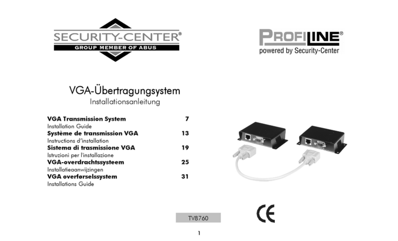
Abus Security Center TV8760 User manual

VGA-Übertragungsystem
Installationsanleitung
VGA Transmission System 9
Installation Guide
Système de transmission VGA 17
Instructions d’installation
VGA-overdrachtssysteem 25
Installatieaanwijzingen
VGA overførselssystem 33
Installations Guide
TV8760
Version 1.3

2
1. Vorwort
Sehr geehrte Kundin, sehr geehrter Kunde,
wir bedanken uns für den Kauf dieses VGA-Übertragungssystems. Sie haben ein Produkt erworben, das nach dem
heutigen Stand der Technik gebaut wurde. Dieses Produkt erfüllt die Anforderungen der geltenden europäischen und nationalen
Richtlinien.
Die Konformität wurde nachgewiesen, die entsprechenden Erklärungen und Unterlagen sind beim Hersteller hinterlegt. Um diesen
Zustand zu erhalten und einen gefahrlosen Betrieb sicherzustellen, müssen Sie als Anwender diese Montageanleitung beachten!
Dieses VGA-Übertragungssystem ermöglicht Ihnen die verlustfreie Übertragung von Videosignalen über 4-paariges CAT5-Kabel bis zu
einer Entfernung von 135 m (bei 640x480 Pixel). Es kann sowohl im privaten als auch im kommerziellen Bereich angewendet werden,
z.B. bei Overheadprojektoren, bei PC-Schulungs-Systemen, in Vorlesungssälen und für den professionellen Auftritt bei Produktshows.
2. Lieferumfang
•2 Stück Sender-/Empfangsmodule für bis zu 135m
•25 cm langes VGA-Kabel
•Montageanleitung
3. Sicherheitshinweise
Öffnen Sie niemals dieses Produkt, um Beschädigungen am Gerät zu vermeiden und Ihren Garantieanspruch nicht zu verlieren.
Das Produkt nur innerhalb des vorgeschriebenen Temperaturbereichs und nur in trockenen Räumen betreiben.Alle Angaben hierzu
finden Sie in den technischen Daten.

3
4. Anschlussplan TV8760
Max. Abstand über CAT 5 UTP/STP Kabel
640x480 Pixel (15MHz) 135m
800x600 Pixel (30MHz) 105m
1024x768 Pixel (60Mhz) 75m
1280x1024 Pixel (100MHz) 60m
135m (max)
Sendermodul Empfängermodul VGA-Display

4
Sendermodul Frontseite Sendermodul Rückseite
4. Anschlussplan TV8760 (Fortsetzung)
Anschlüsse am Sendermodul
TO MONITOR/VGA: Eingang für die VGA-Video-Signale
RJ-45 Ausgang für die Übertragung des gesamten Videosignal über ein CAT 5 UTP oder STP-Kabel

5
Empfängermodul Frontseite Empfängermodul Rückseite
4. Anschlussplan TV8760 (Fortsetzung)
Anschlüsse am Empfängermodul
RJ-45: Eingang für die Übertragung des gesamten Videosignals über ein CAT 5 UTP oder STP Kabel
TO MONITOR/VGA: Ausgangsbuchse für VGA-Signale
Achten Sie darauf, dass Sie die Verbindungsleitung möglichst nicht in der Nähe von spannungsführenden Leitungen verlegen, da dies
in seltenen Fällen zu Interferenzen (schlechte Bildqualität) führt.

6
5. Installation
Achtung: Die folgenden Hinweise sind nur bei Verwendung von UTP-Kabel zu beachten.
DIP-Schalterfunktion: Die DIP-Schalter an der Sender/Empfänger-Rückseite dienen zur Anpassung des Synchronisierungssignals an
die UTP-Kabellänge. Die DIP-Schalter-Einstellung kann bei Verwendung von STP-Kabel vernachlässigt werden.
Die DIP-Schalter-Einstellung erfolgt in Stufen von 1 - 15, dabei werden aktivierte DIP-Schalter-Nummern addiert (z.B. 2 + 3 = Stufe 5).
1. Stellen Sie als Erstes Stufe 5 für Sender und Empfänger ein (DIP-Schalter 2 und 3 aktiviert). Verbinden Sie alle Kabel und
prüfen Sie das Monitorbild.
2. Bei Bildstörungen entfernen Sie als Erstes das UTP-Kabel und erhöhen anschließend die DIP-Schalterstufe
(z.B. 1 + 2 + 3 = Stufe 6). Verbinden Sie das Kabel wieder und prüfen Sie das Bild.
3. Treten immer noch Bildstörungen auf, so wiederholen Sie bitte Schritt 2.

7
Achtung: Die folgenden Hinweise sind bei Verwendung von STP-Kabel zu beachten.
Bei RJ-45-Steckern mit Metallgehäuse muss die Erdungsleitung mit dem Gehäuse verbunden sein.
Wenn Sie einen RJ-45-Verbindung-stecker mit Kunststoffgehäuse verwenden, dann verbinden Sie bitte die Erdungsleitung mit einer
Schraube mit
einem Abstandsbolzen der SUB-D- Buchse am Gehäuse des Senders bzw. Empfängers.
Die Erdungsleitung muss dem Gehäuse verbunden sein!
A
nschluss: STP RJ 45 / Gehäuse: Metal
A
nschluss: STP RJ 45 / Gehäuse: Kunststoff

8
5. RJ-45 PIN-Belegung der TV8760
6. Technische Daten TV8760
PIN Funktion
1 R Video (rot): Pin 1 (+), Pin 2 (-) „balanced“
2 G Video (grün): Pin 4 (+), Pin 5 (-) “balanced”
3 B Video (Blau) Pin 7 (+), Pin 8 (-) “balanced”.
4 Horizontale Synchr.: Pin 3, Vertikale Synchr.: Pin 6
Umgebung VGA, VESA VP&D 1.0, VIP ver 2.0
Video 1VssEingangssignal
Hor. und vert. Synchr.: TTL Standard, max Bandbreite 300kHz
Anwendungen bei: VGA-Monitore, LCD-Bildschirme, Laptops, PCs
Einfügungsdämpfung Weniger als 3dB pro Paar über den Frequenzbereich
Rückflussdämpfung Max. -15dB von DC bis 60Mhz
Eingang: RGB 75 Ohm (DB15 HD) „unbalanced“
Ausgang: RGB 100 Ohm (RJ-45 abgeschirmt) „balanced“
Widerstand
Horiz. und vert. Synchr.: TTL Standard
Übertragungsdistanz 60 – 135m abh. von der Bildauflösung
Kabel für RJ-45 CAT 5 STP oder UTP abh. von der Ausstattung
Temperaturbereich Arbeitsbereich: 0° C – 50°C, Lagerung: 0° C – 50°C,Luftfeuchtigkeit bis 95%
Maße (HxBxT) 24x110 x77 mm

9
VGA Transmission System
Installation Guide
VGA Übertragungsystem 1
Installationsanleitung
Système de transmission VGA 17
Instructions d’installation
VGA-overdrachtssysteem 25
Installatieaanwijzingen
VGA overførselssystem 33
Installations Guide
TV8760
Version 1.3

10
1. Preface
Dear Customer,
Thank you for purchasing this VGA transmission system. This product was designed and built using state-of-the-art technology which
complies with the current standards of domestic and European regulations.
The CE has been proven and all related certifications are available from the manufacturer upon request. To maintain this status and to
guarantee safe operation, it is your obligation to observe these operating instructions.
This VGA transmission system provides you with no-loss transmission of video signals using existing 4 pair CAT 5 cabling up to a
distance of 135m.(at 640x480 Pixels) This system is ideal for classroom video distribution, overhead projector systems, video
information displays, PC-training systems, and tradeshow PC-demo systems.
2. Scope of delivery
•2 transmitter/receiver modules for distances of up to 135m
•25 cm long VGA cable
•Installation instructions
3. Precautions
Never open this product to avoid damaging it and to ensure that your guarantee remains valid.
Operate the camera only within the specified temperature range and in dry rooms. All specifications can be found in the technical data.

11
4. TV8760 connection diagram
Max. distance via CAT 5 UTP cable
640x480 Pixels (15MHz) 135m
800x600 Pixels (30MHz) 105m
1024x768 Pixels (60Mhz) 75m
1280x1024 Pixels (100MHz) 60m
Attention: If you use RJ-45-Jack with metal housing, the shield from the connection cable has to be connected with the metal housing.
Using RJ-45-Jack with plastic housing needs essentialy grounding with the housing of the transmitter/receiver. Therefore connect the
shielding from the cable with the screw of the D-SUB from the transmission system.
135m (max)
Transmitter module Receiver module VGA-Display

12
Transmitter module frontside Transmitter module backside
4. TV8760 connection diagram (continued)
Connections at the transmitter module
TO MONITOR/VGA: input VGA-signal
RJ-45 female: output transmission of the hole videosignal through CAT 5 STP or UTP cable

13
Receiver module frontside Receiver module backside
4. TV8760 connection diagram (continued)
Connections at the receiver module
RJ-45 female: input transmission of the hole videosignal throgh CAT 5 UTP or STP cable
TO MONITOR/VGA: output VGA signal
Make sure that you do not lay the connection line near electrical power lines – in rare cases their proximity may lead to interference
(poor picture quality).

14
5. Installation
Attention: Please comply with the following instructions if you are using CAT5 UTP cable.
DIP switch function: The DIP switches at the back side of transmitter/receiver can be used to adapt the sync signal to the UTP cable
length. This setting can be disregarded on using STP cable.
The DIP-switch setting can be done in stages from 1 -15. The DIP switch numbers are added, the outcome of this is current stage
(e.g. 2 + 3 = stage 5).
1. Please set the DIP switch to stage 5 for transmitter and receiver at first (DIP switch 2 and 3 activated). Then connect all the
cables and check the monitor picture.
2. If interferences occur, please increase the DIP switch stage (e.g. 1 + 2 + 3 = stage 6). Connect the cables again and check the
monitor picture.
3. If still interferences occur please repeat step number 2.

15
Attention: Please comply with the following instructions if you are using CAT5 STP cable.
If you use RJ-45-Jack with metal housing, the shield from the connection cable has to be connected with the metal housing.
Using RJ-45-Jack with plastic housing needs essentialy grounding with the housing of the transmitter/receiver. Therefore connect the
shielding from the cable with the screw of the D-SUB from the transmission system.
Ground cable: Must touch the metal housing
Connector: STP RJ 45
Housin
g
: Metal
Connector: STP RJ 45
Housing : plastic

16
5. RJ-45 PIN-define TV8760
6. Technical specifications of TV8760
PIN Funktion
1 R Video (red): Pin 1 (+), Pin 2 (-) balanced
2 G Video (green): Pin 4 (+), Pin 5 (-) balanced
3 B Video (Blue) Pin 7 (+), Pin 8 (-) balanced.
4 Horizontal Sync.: Pin 3, Vertical Sync.: Pin 6
Environment VGA, VESA VP&D 1.0, VIP ver 2.0
Video 1VssInput signals
Horiz. und vert. Sync.: TTL Standard, 300kHz max bandwidth 300kHz
Devices VGA-Monitors, LCD projection screen, Laptops, PCs
Insertion Loss Less than 3dB per pair over the frequency range
Video Signal Return
loss
Max. -15dB from DC to 60Mhz
input: RGB 75 Ohm (DB15 HD) unbalanced
output: RGB 100 Ohm (RJ-45 shielded) balanced
Impedance
Horiz. and vert. Sync.: TTL Standard
Transmission distance 60 – 135m depend on image resolution
Cable for RJ-45 CAT 5 STP or UTP depending on equipment
Temperature operation: 0° C – 50°C, storage: 0° C – 50°C,humidity: up to 95%
Dimensions (HxWxD) 24x110 x77 mm

17
Système de transmission VGA
Instructions d’installation
VGA Übertragungsystem 1
Installationsanleitung
VGA Transmission System 9
Installation Guide
VGA-overdrachtssysteem 25
Installatieaanwijzingen
VGA overførselssystem 33
Installations Guide
TV8760
Version 1.3

18
1. Préface
Chère cliente, cher client,
Nous vous remercions d'avoir porté votre choix sur ce système de transmission vidéo à paire torsadée. Vous disposez maintenant d’un
appareil faisant appel à une technologie de pointe. Ce produit est conforme aux exigences des directives européennes et nationales en
vigueur.
La conformité de ce produit a été prouvée. Les déclarations et documents correspondants ont été déposés chez le fabricant. Pour que
cette conformité persiste et qu’un fonctionnement en toute sécurité puisse être assuré, lire attentivement ces instructions de montage !
En utilisant un câble CAT5, ce système de transmission VGA permet une transmission sans perte de signaux vidéo, sur une distance
pouvant atteindre 135m (résolution 640x480 Pixel). L’utilisation de ce produit est surtout prévue pour les projecteurs Overhead,
l’interprétation des signaux audio et vidéo dans les salles de conférences, et des exposés professionnels basés sur system
d’ordinateur
2. Livraison
•2 modules émetteurs/récepteurs d'une portée pouvant atteindre 300m
•Un câble VGA d’une longueur de 25cm l
•Instructions de montage
3. Consignes de sécurité
Ne jamais ouvrir le produit, afin d'éviter tout endommagement de l'appareil et la perte du droit à la garantie.
N'utiliser le produit que dans les limites de températures prescrites et dans des locaux secs.Toutes les informations à ce sujet figurent
dans la fiche technique.

19
4. Plan de branchement du TV8760
Distance max sur un câble CAT5 UTP
640x480 Pixel (15MHz) 135m
800x600 Pixel (30MHz) 105m
1024x768 Pixel (60Mhz) 75m
1280x1024 Pixel (100MHz) 60m
Attention: les prises RJ-45 ayant un boîtier métallique doivent être reliées á la masse de l’appareil. Si vous utilisez une prise RJ-45
en plastique, reliez s.v.p la ligne de la masse avec le boulon de la douille du boîtier de du module émetteur / récepteur.
135m (max)
Sendermodul Empfängermodul VGA-Display

20
Face avant du module émetteur Face arrière du module émetteur
4. Plan de branchement du TV8760 (suite)
Raccordement du module émetteur
TO MONITOR/VGA: Entrée du signal Vidéo VGA
RJ-45 Sortie pour la transmission du signal Vidéo complet sur un câble CAT5 UTP ou STP
Other manuals for Security Center TV8760
1
Table of contents
Languages:
Other Abus Microphone System manuals
Popular Microphone System manuals by other brands

Askey Computer
Askey Computer RT410W 802.11 a Operation manual

Telex
Telex ENG-100 UHF Specifications

JTS
JTS E-7HHSETD/ 5 instruction manual

K&K Sound Systems
K&K Sound Systems Meridian PRO installation instructions

FITNESS AUDIO
FITNESS AUDIO SDR-1716 operating manual

Silicon Laboratories
Silicon Laboratories ZigBee user guide