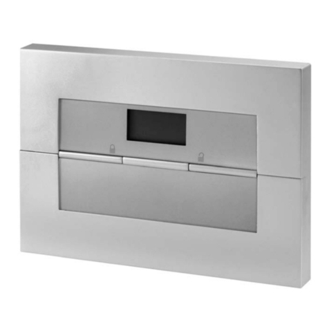
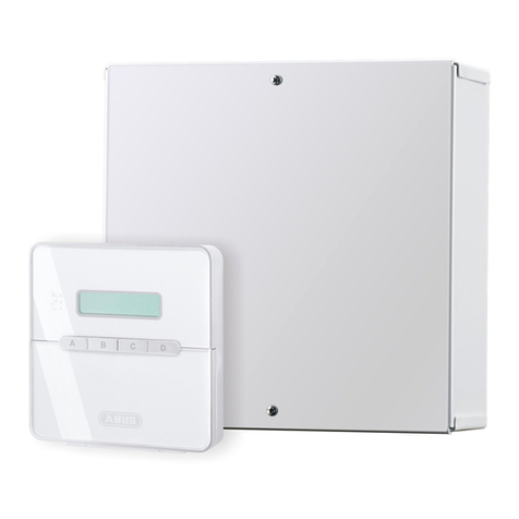
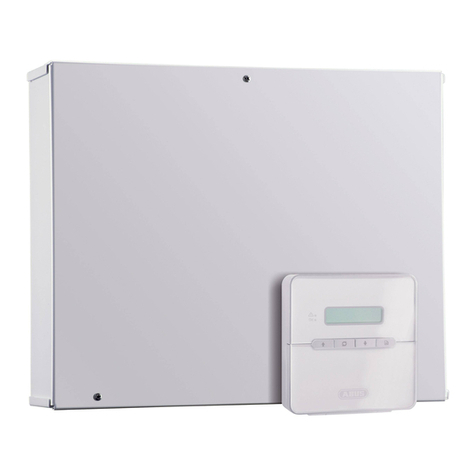
Abus Terxon LX Instruction Manual

Perfect security for home and office
Inv. 11738099
Terxon LX
ADMINISTRATION MANUAL


I
Contents
1. Introduction................................................................................................................................................. 2
1.1. General .................................................................................................................................................. 2
1.2. Access to user menu ............................................................................................................................. 2
1.3. Selecting an option ................................................................................................................................ 2
1.4. Exiting the user menu ............................................................................................................................ 3
2. Options in the user menu .......................................................................................................................... 3
2.1. Option 1: Omit Zones............................................................................................................................. 3
2.2. Option 2: Shunting 24hr Zones.............................................................................................................. 3
2.3. Option 3: System Options...................................................................................................................... 4
2.3.1. Option 3-1: Enable Chime .......................................................................................................... 4
2.3.2. Option 3-2: Adjust volume .......................................................................................................... 4
2.3.3. Option 3-3: Time Switches.......................................................................................................... 4
2.3.4. Option 3-4: Auto Sets.................................................................................................................. 5
2.4. Option 4: Test Options........................................................................................................................... 6
2.4.1. Option 4-1: Walk Test ................................................................................................................. 6
2.4.2. Option 4-2: Bell Test ................................................................................................................... 7
2.5. Option 5: Engineer Tools ....................................................................................................................... 7
2.5.1. Option 5-1: Engineer Access ...................................................................................................... 7
2.5.2. Option 5-2: Starting a Call Back ................................................................................................. 8
2.6. Option 6: Time and Date........................................................................................................................ 8
2.6.1. Option 6-1: Set Time................................................................................................................... 8
2.6.2. Option 6-2: Set Date ................................................................................................................... 9
2.7. Option 7: Custom Text........................................................................................................................... 9
2.7.1. Option 7-1: Zone Text................................................................................................................. 9
2.7.2. Option 7-2: Partiton Text............................................................................................................. 9
2.8. Option 8: Set Up Users........................................................................................................................ 10
2.8.1. User types................................................................................................................................. 10
2.8.2. Option 8-1: User Code.............................................................................................................. 11
2.8.3. Option 8-2: User Name............................................................................................................. 12
2.8.4. Option 8-3: Customise Menus .................................................................................................. 13
2.9. Option 9: Log ....................................................................................................................................... 13
2.9.1. Option 9-1: View Log ................................................................................................................ 13
2.9.2. Option 9-2: Print Log................................................................................................................. 14
2.9.3. Option 9-3: View Access Log.................................................................................................... 14
2.9.4. Option 9-4: Print Access Log ....................................................................................................15
3. Letter Keys ................................................................................................................................................ 15
4. Zone Numbers .......................................................................................................................................... 16
5. Event Messages........................................................................................................................................ 17
6. System Plan .............................................................................................................................................. 21
6.1. General System Data........................................................................................................................... 21
6.2. User Data............................................................................................................................................. 24
6.3. Zone Data ............................................................................................................................................ 25
6.4. Maintenance ........................................................................................................................................ 26
6.5. Engineer Data ...................................................................................................................................... 27
7. Brief Overview .......................................................................................................................................... 28
These operating instructions are an important product accessory. They contain important information on
operating the burglar alarm system. Bear this in mind if you pass the product on to others. Store these
instructions in a safe place for future reference.
2
1. Introduction
Dear Customer,
Thank you for purchasing the TERXON L burglar alarm system. You made the
right decision in choosing this state-of-the-art technology, which complies with the
current standards of domestic and European regulations.
The CE has been proven and all related certifications are available from the
manufacturer upon request.
The TERXON L system uses the most modern technology for the comprehensive,
flexible protection of your private and commercial property. In combination with
other components such as detectors and signal transmitters, it secures the areas
to be monitored.
1.1. General
To ensure proper and safe operation, it is your obligation to observe these
operating instructions!
These administrator instructions describe the options in the user menu and are
intended for persons with advanced access rights following complete installation.
For example, you can enter new user codes, view the event memory or exclude
zones from monitoring. If you have any questions on activating, deactivating or
resetting the burglar alarm system, refer to the operating instructions.
If you have any questions on installation or other problems, contact your engineer
or authorised dealer.
To ensure smooth operation, discuss any system changes with the engineer. It will
help you to document your system during the initial installation. You can use the
tables at the end of the manual for this purpose.
1.2. Access to user menu
1. Enter your user code on the keypad or hold your chip-key against the
control panel.
2. Press
The “Omit Zones” option is displayed.
Important: ...................................................................................................................
Access to options depends on the user menu (please see “User types“ on page
10).
1.3. Selecting an option
You can select an option in two ways:
1. Select an option with or and confirm with .
2. Press a number key (0–9), for example 1 for “Omit Zones”, and confirm
with .
BANNER TEXT
17:30 Sun 01 JAN
Set Partitions ?
Ptns > ***.....
User Menu
1:Omit Zones

Administration Manual – Terxon L
3
1.4. Exiting the user menu
To return to the normal display, press repeatedly to jump back through the
menus step by step until the time and date are displayed.
2. Options in the user menu
2.1. Option 1: Omit Zones
You may want to exclude some zones before activating the system. For example,
one room still needs to be used while the rest of the system is activated. This
option allows you to select zones you want to exclude.
Important: ...................................................................................................................
If the system is deactivated, the settings made are deleted. This prevents
zones from being omitted accidentally.
Important: ...................................................................................................................
You can only omit zones that have been set up as omittable (see Installation
Instructions, Option 11).
1. Press to open the “Omit Zones “menu.
2. Press the and keys or select the zone to be isolated by entering
the 4-digit zone number (please see “Zone Numbers“ on page 16 for
details of numbering).
3. Press to change the state of the zone (omitted means that the zone
will be omitted).
4. Press to change to the next zone, or to exit the menu.
2.2. Option 2: Shunting 24hr Zones
This option allows you to isolate all 24-hour zones in specific partitions. The zones
are then permanently excluded from system monitoring. However, these zones
must have the “Isolate” attribute (see Installation Instructions, Option 11).
Important: ...................................................................................................................
Zones remain shunted until you use the Reinstate 24hr option (see below).
Important: ...................................................................................................................
Reinstating Zones may start the exit timer, depending on the selected setting,
which can be “Unshunt”, “No Exit” or “Unshunt & Exit” (see Installation
Instructions, Option 45).
1. Press to select Shunt 24-hr Zns.
2. Press 1 to shunt zones or 2 to reinstate shunted zones.
3. Press the number keys to select the partitions you want to shunt or
reinstate, and confirm with . Every displayed partition is now
shunted/reinstated. (A “*” means that the partition will not be
shunted/reinstated, and “.” means that you have no access to this partition.)
1=Shunt 24hr
2=Reinstate 24hr
Shunt partitions
Ptns > 1*......
User Menu
1: Omit Zones
0002 is Armed
User Menu
2:Shunt 24hr Zns

Administration Manual – Terxon L
4
2.3. Option 3: System Options
2.3.1. Option 3-1: Enable Chime
Select this option to define partitions that run the chime function. If this attribute is
released in a partition and the zones support the chime (see Installation
Instructions, Option 11), a signal tone sounds when a zone is triggered in
deactivated state. The partitions remain in the chime option until you deactivate the
function.
A zone can emit one, two or three tones, depending on the door chime setting (see
Installation Instructions, Option 11).
The door chime sounds only on operating panels and alarm sounders that belong
to the same partitions as the zone that is triggered.
If a chime sounds, the operating panels display the zone number (if set; see
Installation Instructions, Option 45-08).
1. Press to display “System Options”.
2. Press to select “Enable Chime”.
3. Press the number keys to select partitions you want to release for the door
chime and confirm with . Every partition number displayed is released
for the door chime. (A “*” means that the partition is not released for the
door chime, and a “.” means that you have no access to the partition.)
2.3.2. Option 3-2: Adjust volume
Under this menu item, you can set the volume of the additional alarm sounders
connected to the alarm system.
1. Press to select this option.
2. Press and or 2 to select “Adjust Volume”, and confirm by
pressing .
3. Press and to adjust the volume or enter a value from 0-7 (“off” to
“maximum”).
4. Confirm the displayed value with or press to exit the menu
without making any changes.
2.3.3. Option 3-3: Time Switches
With this option, you can set the three time switches provided for
activating/deactivating the outputs of the alarm system at defined times. A time
switch works independently of the system state.
For each time switch, you can define up to three different on/off periods and select
weekdays on which the time switches trigger.
The outputs controlled by the time switches are described in detail in the
Installation Instructions, Option 30.
System Options 1
Enable Chime
Chime On Prtns:
Ptns > 1*......
User Menu
3:System Options
User Menu
3:System Options
System Options 2
Adjust Volume
Adjust Volume
>>>>>>> (MAX)

Administration Manual – Terxon L
5
1. Press to display “System Options”.
2. Press and , or 3, to select the “Time Switches” option. Confirm
with .
3. Press and or a number key (for example 3) to set a time switch,
and then press .
4. Press and or a number key (1–9) to define the on/off time or the
weekday on which the time switch is to trigger. Confirm with .
Each time switch has three possible on/off periods. For each time switch, you can
define the activation/deactivation time and the weekdays.
Important: ...................................................................................................................
You can manually skip a time switch by pressing 0 and then pressing to
change the current state.
5. As shown on the left, you can now define the on/off time. The number in
brackets shows the time period you are currently defining.
Specify the time (e.g. 21:00h) and confirm with .
Go to step 4 or press to exit the menu.
6. You can now define the weekdays on which the time switches are to
trigger. The number at top left shows the period in which the time switch is
active. Press 1–7 to select the weekdays, and confirm with . Go to
step 4 or press to exit the menu.
2.3.4. Option 3-4: Auto Sets
Here you can define up to three automatic time switches. Each time switch can be
linked to one or more partitions. These partitions are then activated/deactivated at
the times you define. Delay is possible until the deactivation time is reached. A final
cancellation of automatic activation is not possible.
For each automatic time switch, you can define three different on/off times. You
can also define the weekdays on which the time switches are to trigger.
Important: ...................................................................................................................
The alarm sounders of the operating panels sound one minute before
automatic activation. Entering a user code delays activation by the preset time
duration (see timeout settings in the Installation Instructions, Option 44-16).
1. Press to select this option.
2. Press and or 4 to select automatic activation and confirm with
.
3. Press and or a number key (1–3) to edit an automatic time
switch. Confirm with .
4. Press and or a number key (1–9) to select the on/off time or the
weekdays. Confirm with .
Time Switch 1
Time Switch 1
On (1) 00:00
Time Switch 1
On (1) >00:00
1 Operates On :-
>.......
System Options 4
Auto Sets
Auto Set 1
Auto Set 1
On (1) 00:00
User Menu
3:System Options
User Menu
3:System Options
System Options 3
Time Switches

Administration Manual – Terxon L
6
For each time switch, you can define up to three different on/off times. For each
time switch, you can define the activation time, the deactivation time and the
weekdays.
Important: ...................................................................................................................
You can manually skip a time switch by pressing 0 and then pressing to
change the current state.
5. As shown on the left, you can now define the on/off time. The number in
brackets shows the time period you are currently defining.
Specify the time (e.g. 21:00h) and confirm with .
Go to step 7 or press to exit.
6. You can now define the weekdays on which the time switches are to
trigger. The number at top left shows the period in which the time switch is
active. Press 1–7 to select the weekdays, and confirm with .
7. Press and use the number keys to assign the partitions to the
automatic time switches. Confirm the assignment with . All partition
numbers displayed are assigned. (A “*” means that the partition is not
released, and a “.” means that you have no access to this partition.)
Go to step 4 or press to exit.
Important: ...................................................................................................................
If the engineer is in the installation menu, the system is also automatically activated.
2.4. Option 4: Test Options
2.4.1. Option 4-1: Walk Test
Under this menu item, you can test that zones are operating correctly. You can
only test partitions to which you have access.
Each tested zone is logged in the event memory. To view the event memory, see
“Option 9-1: View Log” on page 13.
1. Press to select this option.
2. Confirm with to select “Walk Test”.
3. Press the number keys to select the partitions you want to test and confirm
with .Every partition number displayed is released for the walk test. (A
“*” means that the partition is not tested, and a “.” means that you have no
access to this partition.)
4. Now walk through all your partitions and trigger all sensors.
For each zone that you trigger, the integrated alarm sounders issue a
signal time and the display shows the triggered zone.
5. When you have completed the test, press .
User Menu
4:Test Options
Auto Set 1
On (1) >00:00
1 Operates On :-
> .......
Auto Set 1
Ptns > **
Test Options 1
Walk Test
Walk Test
Ptns > 1*......
0003 Active
Esc To Stop Test
& View Zones

Administration Manual – Terxon L
7
6. The state of the lowest zone number is displayed. Press to change to
the display of the next tested zone.
7. Press to exit the menu.
2.4.2. Option 4-2: Bell Test
Select this option to test the alarm sounders, the strobe and the bell.
1. Press .
2. Press and or 2 to select “Bell Test” and confirm with .
3. Press the number keys to select the partitions you want to test and confirm
with . Every partition number displayed is released for the signal test.
(A “*” means that the partition is not tested, and a “.” means that you have
no access to this partition.)
4. The bell sounds. Press to run the next test.
5. The bell sounds and the strobe flashes. Press to run the next test.
6. Only the strobe flashes. Press to run the next test.
7. The alarm sounders trigger. Press to run the next test.
8. The strobe and the alarm sounders switch off. Press to repeat the test
or to exit the menu.
Important: ...................................................................................................................
Each test can be selected individually.
2.5. Option 5: Engineer Tools
2.5.1. Option 5-1: Engineer Access
With this option, you define the period in which the engineer can log into the
system. When this period expires, the engineer can continue working, but the
engineer cannot log in again.
The period starts from the set time and can be either 5 minutes or 4 hours. You
can terminate the period at any time.
Important: ...................................................................................................................
The default is set to unlimited.
1. Press to select this option.
2. Press to select “Engineer Access”.
User menu
5:Engineer Tools
Engineer Tools 1
Engineer Access
Panel Zone 1
0001 Healthy
User Menu
4:Test Options
Test Options 2
Bell Test
Bell Test
Ptns > 12......
Bell Test 1
Bell Only
Bell Test 2
Bell & Strobe ON
Bell Test 3
Strobe Only
Bell Test 4
Alarm Sounder On
Bell Test 0
Bell/Strobe OFF

Administration Manual – Terxon L
8
3. Press and or a number key (1–4) to select an option, and confirm
with .
You can choose between 5 Min Window and 4 Hour Window. In this time, your
engineer can log into the system. Confirm with .
If you select “Infinite”, the engineer can log in at any time.
If you select “Close Window”, the current access is terminated immediately.
2.5.2. Option 5-2: Starting a Call Back
Select this option to connect the integrated modem to a remote site that is running
the Downloader software. When the connection is made, the remote site can
upload data and change settings in the control panel. The connection continues
until the remote site disconnects it.
Important: ...................................................................................................................
Select this option only if requested by your engineer.
Important: ...................................................................................................................
Your engineer can establish the connection, dependent on the access mode
set (see Installation Instructions, Option 51-3).
1. Press to select this option.
2. Press and or 2 to select remote access and confirm with .
3. Press and or a number key (1–4) to dial a number (see
Installation Instructions, Option 51-4). Confirm with to start dialling.
4. After the connection is made, the system returns to normal. If the
connection cannot be made, press to cancel dialling.
2.6. Option 6: Time and Date
2.6.1. Option 6-1: Set Time
Here you can set the system time.
Important: ...................................................................................................................
At 2am on predefined days, the system sets the time automatically according to
local summer/winter time.
1. Press to select this option.
2. Press to select system time.
Calling On : 1
Hit ESC to abort
User Menu
6:Time And Date
Time and Date 1
Set Time
User Menu
5:Engineer Tools
Engineer Tools 2
Call Service?
Start Callback 1

Administration Manual – Terxon L
9
3. To change the time, enter 4 digits (hhmm) for the current time.
4. Confirm the displayed time with or exit the menu without changes by
pressing .
2.6.2. Option 6-2: Set Date
Here you can set the system date.
1. Press to select this option.
2. Press and or 2 to select system date and confirm with .
3. To change the date, enter 6 digits (ddmmyy) for the current date.
4. Confirm the displayed date with or press to exit the menu without
changing the date.
2.7. Option 7: Custom Text
2.7.1. Option 7-1: Zone Text
Select this option to adapt the zone texts to the user’s wishes. In this way, zones
can be better identified by the user.
1. Press to select this option.
2. Press to select a zone text.
3. Press and or a number key to select a zone and confirm with
.
4. Enter a text by pressing the number keys containing the letters you want
(see chapter 3 “Letter Keys“ on page 15). Confirm the displayed value with
or press to exit the menu without changing the text.
2.7.2. Option 7-2: Partiton Text
Select this option to adapt the partition texts to the user’s wishes. In this way,
partitions can be better identified by the user.
1. Press to select this option.
2. Press and or 2 to select partition text and confirm with .
3. Press and or a number key to select a partition and confirm with
.
4. Enter a text by pressing the number keys containing the letters you want
(see chapter 3 “Letter Keys“ on page 15). Confirm the displayed value with
or press to exit the menu without changing the text.
Enter new time:-
11:44
User Menu
6:Time And Date
Current Date:-
01/01/06
Custom Text 1
Zone Text
User Menu
7:Custom Text
User Menu
7:Custom Text
Time And Date 2
Set Date
Zone 0001
^one 0001
Custom Text 1
Prtn Text
Viewing Prtn 1

Administration Manual – Terxon L
10
2.8. Option 8: Set Up Users
This option allows you to define users to operate the alarm system (up to 99 users).
To install a user, define the following items:
•User code: The user enters this code at the operating panel (e.g. to
activate/deactivate the system).
•User type (e.g. user): This setting defines what access rights the user has to
the system (see chapter 2.8.1 “User types“ on page 10).
User access to menu functions is first defined by the user type, but it can be
adapted later if necessary (see “Option 8-3: Customise Menus“ on page 13).
•Access rights to partitions: Users can activate, deactivate and
reset only those partitions to which they have access.
Important: ..................................................................................................................
A user cannot modify another user who has a lower number (level) (e.g. user 3
cannot modify user 2).
Important: ..................................................................................................................
To delete a user, set the user type to “Not in use”.
2.8.1. User types
The following 12 user types are possible:
Manager
Users of this type have access to all menu items and options. From every
operating panel, they can activate/deactivate all assigned partitions. In the
basic setting, user 001 is defined as the manager and has the default password
1234 (4-digit) or 123400 (6-digit).
Standard Global
This user type has access to functions 1, 2, 4 and 5 of the administrator menu
(see “Option 8-3: Customise Menus“ on page 13). Activation/deactivation is
possible from every operating panel.
Standard User
Like advanced users, users of this type have access to functions 1, 2, 4 and 5
of the administrator menu (see “Option 8-3: Customise Menus“ on page 13).
However, they can only activate/deactivate partitions from an operating panel
to which the partitions are assigned. For example, if a user has access to
partitions 1 and 2 and uses an operating panel that has access to partition 2
only, the user can activate/deactivate partition 2 only.
Prox Tag User
This user type holds the chip-key against the operating panel and has no user
code. These users have access rights to options 1, 2, 4 and 5. They can
activate/deactivate assigned partitions from any operating panel.
Easy Set
During activation/deactivation, all assigned partitions are activated/deactivate
and the operating panel displays no options. The user can activate/deactivate
from any operating panel. During deactivation, the user code deactivates all
assigned partitions.

Administration Manual – Terxon L
11
Reset only
Users of this type have access to user options 1 and 2. They can reset 24-hour
alarms from any operating panel.
Panic Code
This user type has no access to the menu and cannot activate or deactivate.
When this code is entered, a panic alarm is triggered (the alarm sounders and
the bell sound and the strobe flashes).
Important: ..................................................................................................................
To enable a panic code, set “Duress Allow” to Yes (see Installation Instructions,
Option 45-24).
Duress Code
Users of this type have the same access rights as advanced users but can
trigger a silent alarm by entering the code. This alarm can for example be
transmitted to an emergency centre. In the event of a threat, the user can
operate the alarm system normally and at the same time send an alarm.
Important: ..................................................................................................................
To enable a duress code, set “Duress Code” to Yes (see Installation
Instructions, Option 45-24).
Access
This user type has no access to the menu and cannot activate/deactivate.
Entering this user code causes a temporary switching of the outputs of type
“Code accepted”, “Access”, or “Access code” (see Installation Instructions,
Option 30), which can be used to activate an electric door lock or similar.
Shunt
Users of this type have no access to the menu and cannot activate or
deactivate. When this code is entered, the corresponding zones are isolated
(see Installation Instructions, Option 13). The isolated zones can be reactivated
by entering the code again.
Set Only
Users of this type can activate specific partitions from any operating panel, but
they cannot deactivate.
Not in Use
This user has no rights. Use this type to deactivate an existing user.
2.8.2. Option 8-1: User Code
With this option, you define the user code, the user type and the partitions to which
the user has access.
1. Press to select this option.
2. Press to select “Code”.
3. The lowest available user number is displayed. Press to select this
user if desired. You can also enter a number or press and to
select a different user.
User Menu
8:Set Up Users
User Codes 1
Code
Define new users
User no. 05

Administration Manual – Terxon L
12
Important: ..................................................................................................................
Press to view the numbers of already defined users. Press any key to
return to the previous display.
4. Now enter the user code (4- or 6-digit; see Installation Instructions, Option
47) and confirm with or use the chip-key.
If you press without entering a new code, the previous code is
retained.
Important: ..................................................................................................................
If a message “NOT ACCEPTED” appears, this indicates that this code has
already been assigned, and you must enter another code. Press and try
another code.
5. Press and or press a number key (1–9) to select the user type
(please see “User types“ on page 10) and confirm with .
6. Press the number keys to select the partitions to which the user is to have
access and confirm with . Every displayed partition is now assigned to
the user. (A “*” means that the partition is not assigned, and a “.” means
that you have no access to this partition.)
Important: ..................................................................................................................
If the Local Setting option is selected (Installation Instructions, Option 45-11),
the user can activate the system only if the operating panel is assigned to the
respective partition.
7. Go to step 3 or press to exit the menu.
2.8.3. Option 8-2: User Name
Select this option for entering a name for each user. If you view the event list (see
Event Messages on page 17), you can press to switch between the displayed
user number and user name for the corresponding event entries. Up to 15
characters are possible.
1. Press to select this option.
2. Press and or 2 to select user name and confirm with .
3. Press and to select a user or enter the user number and confirm
with .
4. Enter a user name by pressing the number keys containing the letters you
want (see chapter 3 “Letter Keys“ on page 15).
Confirm the selection with .
5. Press to exit the menu.
User menu
8:Set Up Users
User 01
User 01
Prox Tag or Code
----
User 05 Prtns
Ptns > 1*......
User Codes 2
User Name

Administration Manual – Terxon L
13
2.8.4. Option 8-3: Customise Menus
Access to the menu options is defined at first by the user type. However, this
option allows you to raise or lower access options individually.
1. Press to select this option.
2. Press and or 3 to select Customise Menu and confirm with .
3. Press and to select a user or enter the user number and confirm
with .
4. Define the user options you want to assign to this user and confirm with
. Pressing 1–9 selects (option number is displayed) and locks (“*” is
displayed) the respective option. The options are:
1 = Omit Zones 6 = Date And Time
2 = Shunt 24hr Zns 7 = Custom Text
3 = System Options 8 = Set Up Users
4 = Test Options 9 = Log
5 = Engineer Tools
5. Press twice.
2.9. Option 9: Log
2.9.1. Option 9-1: View Log
Under this menu item, you can view the 2000 events in the event memory. The
memory contains date and time specifications of system events such as
activation/deactivation of partitions, isolating of zones, triggering of a duress code
or communications problems. For further information on event messages, see
chapter 0 on page 16.
1. Press to select this option.
2. Press to select “View Log“.
3. Press and to scroll through the events ( displays earlier
events). To go to the next event, press the number keys:
1 = Alarms 6 = User codes
2 = 24-hr alarms 7 = Set Partitions
3 = Fire alarms 8 = Unset Partitions
4 = Panic alarms 9 = Entry
5 = Zone tamper
4. If required, press to see further details of an event. Press 0 to view
the event list starting from a specific point (e.g. starting with event 30).
5. To fix a new point, press and then again.
6. Press to exit the menu.
User Menu
8:Set Up Users
User Menu
9:Log
Ptns : 12......
10:50:10 23/04
User Dodes 3
Customise Menus
User 01
User 01
UNSET PRTNS:
10:50:10 23/04
Menu Options:-
> .123456789
Log Functions 1
View Log

Administration Manual – Terxon L
14
2.9.2. Option 9-2: Print Log
If a printer is connected to the alarm centre, you can print all events or events
starting from a specific point.
1. Press to select this option.
2. Press and , or 2 to select printing the event memory, and confirm
by pressing .
3. Press and or enter a 4-digit number to define the number of
events to be printed. Confirm the selection with .
4. Press and or enter a 4-digit number to define the point at which
printing is to start. For example, if you want to print 10 events and enter
event number 50 as the starting point, the system prints events 50–59.
Important: ...................................................................................................................
Every printed event needs more than one line.
To cancel printing, start a new print process with 0 events.
Important: ...................................................................................................................
After once using the option “Print Log”, the system changes to automatic print
mode, in which every new event is printed immediately. Switch off the printer to
stop printing.
2.9.3. Option 9-3: View Access Log
This option enables you to view the contents of the access memory. This records
every entry of a typed access code (for opening doors).
1. Press to select this option.
2. Press and or 3 to select viewing the access memory, and
confirm by pressing .
3. Press and to scroll through the events ( displays earlier
events).
4. Press to exit the menu.
User Menu
9:Log
User Menu
9:Log
Log Functions 2
Print Log
How many events?
0030
With offset of:-
0030
Log Functions 3
View Access Log
Name:- User 02
02:35:48 01/05

Administration Manual – Terxon L
15
2.9.4. Option 9-4: Print Access Log
If a printer is connected to the alarm centre, you can print all or selected events of
the access memory.
1. Press this option.
2. Press and or 4 to select printing the access memory, and confirm
by pressing .
3. Press and or enter a 4-digit number to define the number of
events to be printed.
Confirm the selection with .
4. Press and or enter a 4-digit number to define the point at which
printing is to start. For example, if you want to print 10 events and enter
event number 50 as the starting point, the system prints events 50–59.
Important: ..................................................................................................................
Every printed access event needs more than one line.
To cancel printing, start a new print process with 0 events.
Important: ...................................................................................................................
After once using the option “Print Access Log”, the system changes to
automatic print mode, in which every new event is printed immediately. Switch
off the printer to stop printing.
3. Letter Keys
The following table shows how to enter letters on the number pad. For example,
press “2” twice to enter “B”.
After entering a letter, you can press to move the cursor one step forward.
Press to move one step back.
Important: ...................................................................................................................
After you reach the end of the series of letters on a key, you can return to the
beginning of this series by pressing the key again.
Important: ...................................................................................................................
<sp> stands for space
Key Letter
1 . , ? ! 1 @ “ - & ’
2 A B C 2 a b c
3 D E F 3 d e f
4 G H I 4 g h i
5 J K L 5 j k l
6 M N O 6 m n o
7 P Q R S 7 p q r s
8 T U V 8 t u v
9 W X Y Z 9 w x y z
0 <sp> 0 , # *
User Menu
9:Log
Log Functions 4
Print Access Log
How many events?
0030
With offset of:-
0030

Administration Manual – Terxon L
16
4. Zone Numbers
Every zone has its own 4-digit number. This number has the following format:
The first digit is the bus number. This is the bus number of the device to which the
zone is connected (0 stands for zones directly connected to the mainboard of the
alarm centre).
The next two digits stand for the device address to which the zone is connected
(00 for direct connection to the mainboard).
8 zones constitute a device address, so that every 8-zone auxiliary has its own
device address.
The final digit stands for the zone number of the selected device.
Example:
Zone number 2031: Bus no. 2, device address no. 03, zone no. 1
If you scroll through the zone numbers, only valid numbers are displayed. For
example: after 0008 (zone 8 on the alarm centre) comes 1011 (bus no. 1, device
no. 01, zone 1).

Administration Manual – Terxon L
17
5. Event Messages
Event Description
--- NO EVENT --- Not used
### LECS or REMS The number of operating panels connected to the system
### NODE R# ADD Operating panel added to a wired auxiliary.
# Bus number, ## Auxiliary number, R# Operating panel number
### NODE R# LOST Operating panel R# was removed from the wired auxiliary.
### NODE R# TAMP Tamper alarm triggered by operating panel R#.
### NODE'S Number of connected auxiliaries
### XNODE'S Number of connected wired auxiliaries
#### OFF TEST Zone number #### removed from test function.
#### OMITTED Zone number #### hidden???
#### REINSTATED Zone number #### reinstated
#,## LEC LOST Operating panel on bus #, device number ##, was removed.
#,## LEC TAMPER Operating panel on bus #, device number ##, triggered a tamper
alarm.
#,## NODE ADDED Auxiliary on bus # with device number ## was added.
#,## NODE FUSE Auxiliary on bus # with device number ## has blown a fuse.
#,## NODE LOST Auxiliary on bus # with device number ## was removed.
#,## NODE TAMPER Auxiliary on bus # with device number ## triggered a tamper alarm.
#,## REM ADDED Operating panel on bus #, device number ##, was added.
#,## REM LOST Operating panel on bus #, device number ##, was removed.
#,## REM TAMPER Operating panel on bus #, device number ##, triggered a tamper
alarm.
#,## XNODE ADDED Wired auxiliary on bus # with device number ## was added.
#,## XNODE FUSE Wired auxiliary on bus # with device number ## has blown a fuse.
#,## XNODE LOST Wired auxiliary on bus # with device number ## was removed.
#,## XNODE TAMP Wired auxiliary on bus # with device number ## triggered a tamper
alarm.
24 Hr PARTITIONS:- 24-hour alarm in partition
24H RESTORE #### 24-hour alarm of zone #### was reset.
24Hr ALARM #### 24-hour alarm in zone ####
24HR OMIT:- Zone with “isolate 24-hour zones” was hidden.
24HR REINST:- Zone with “isolate 24-hour zones” was reinstated.
ABORT ON PARTITIONS:- Alarm in partition – aborted
ACCESS ## Code of user ## entered
ACCESS ### Code of user ### entered
ACCESS #### Code of user #### entered
ACCESS FAILED Access denied
ACCESS ZONE #### Access zone #### triggered
ALARM #### Alarm in zone ####
ALARM PARTITIONS: Alarm in partition
ATE L.F. ALL Fault in both communication routes of modem
ATE L.F. RESTORE Communication restored
ATE L.F. SINGLE Fault in one communication route of modem
AUTOSET # OFF Automatic activation off
AUTOSET # ON Automatic activation on
AUX RESTORE #### Technical alarm of zone #### reset
AUX/BELL TAMPER Tamper alarm in technical zone/bell
AUXILIARY #### Technical alarm in zone ####
AUXILIARY # TAMP Not used
AUXILIARY FUSE Fuse fault in auxiliary device
BATTERY FAULT Not used
BATTERY LOAD TST Battery test conducted
BATTERY LOW Battery low
BATTERY MISSING Battery missing
BATTERY RESTORE Battery restored
BEAM PAIR #### First trigger of linked zone ####
BELL BOX TAMPER Not used
BELL FUSE Bell fuse triggered
BELL TAMP OMIT Bell tamper omitted after expiry of confirmation period
BELL TESTED:- Bell in partitions – tested
BELLS ACTIVE:- Bell active in partitions -
CHANGE CODE ## User code for user ## changed
CHANGE CODE ### User code for user ### changed
CHANGE TAG ## Chip-key for user ## changed
CHANGE TAG ### Chip-key for user ### changed
CHNG CODE #### User code for user #### changed
CHNG TAG #### Chip-key for user #### changed

Administration Manual – Terxon L
18
Event Description
CNFG CHANGE ### Configuration of user ### changed
CNFG CHANGE #### Configuration of user #### changed
CODE ## Code of user ## entered
CODE ### Code of user ### entered
CODE #### Code of user #### entered
CODE LOCK # OFF Code lock # off
CODE LOCK # ON Code lock # on
CODE LOCKED ## User number ## tried to enter user code while locked.
CODE LOCKED ### User number ### tried to enter user code while locked.
CODE LOCKED #### User number #### tried to enter user code while locked.
CODE TAMPER Operating panel locked for 5 min due to invalid user code entry
COMMS FAILED Integrated modem could not connect to emergency command centre
COMMS TEST CALL Test call started
CONFIG CHANGE ## User configuration ## changed
DATE CHANGED AT System date changed on …
DATE CHANGED TO System date changed to …
DEFAULT USER User code 01 (administrator) to default
DEFAULT USER ## Not used
DEFAULT USER ### Not used
DEFAULT USER #### Not used
DEFERRED SET:- Delayed activation of partitions
DL DISCONNECT FL) Downloader disconnected with an error
DL DISCONNECT OK Downloader disconnected
DURESS CODE ## Duress alarm user ##
DURESS CODE ### Duress alarm user ###
DURESS CODE #### Duress alarm user ####
ENG HW DEFAULTED Factory reset of alarm centre
ENGINEER ARRIVES Engineer has logged into the system.
ENGINEER DEPARTS Engineer has logged out of the system.
ENTRY TIME-OUT:- Entry timeout in partition expired
ENTRY ZONE #### Entry timeout of zone #### started.
EXIT CANCELLED:- Exit timeout for partition … cancelled.
EXIT STARTED:- Exit timeout for partition … started.
EXT LINE FAULT Not used
EXT LINE RESTORE Not used
FACTORY RESTART Factory settings loaded
FIRE ALARM #### Fire alarm in zone ####
FIRE PARTITIONS:- Fire alarm in partition
FIRE RESET:- Fire alarm reset
FIRST KNOCK #### First activation of zone number #### (zones with the double
confirmation attribute)
FROM REMOTE #,## Not used
HI-SECURITY SET: Activation of partitions with high security
KEYPAD PANIC ### Panic alarm triggered on operating panel ### (keys 1 and 3 pressed)
KEYSWITCH ### Keyswitch zone #### activated
LOCAL ON LINE Local connection with downloader
LOCAL SERV CALL Local connection with downloader
LOCAL SERV END Not used
LOCKSET #### ON Keyswitch zone #### activated
LOCKSET #### OFF Keyswitch zone #### deactivated
LOCKSET PARTITION ON Key for partition released
MAIN POWER ON Mains power on in the alarm centre
MAINS POWER OFF Mains power off in the alarm centre
MASK FLT S #### Zone #### masked during activation
MASK FLT U #### Zone #### masked during deactivation
MASK TMP S #### Masking zone #### masked during activation
MASK TMP U #### Masking zone #### masked during activation
MENU TIMEOUT ## Menu abort for user ## and return to standby display
MENU TIMEOUT ### Menu abort for user ### and return to standby display
MENU TIMEOUT #### Menu abort for user #### and return to standby display
MODEM LOCKOUT Modem locked (after 4 failed attempts)
NETWORK # FUSE Fuse in bus # triggered
NODE TAMP OMIT Wired auxiliary tamper omitted after expiry of confirmation period
NORM. REST. #### Normal alarm restored
OCCUPANCY SET System activation during operation
ON LINE TO # Online to remote access point
ON-SITE RESTART Restart in the installation
PA PARTITIONS:- Panic alarm in partitions
PANEL LID TAMPER Tamper in panel lid of alarm centre
PANEL STARTED Alarm centre is operational
Other manuals for Terxon LX
1
Table of contents
Other Abus Security System manuals

Abus
Abus KeyGarage 787 Manual

Abus
Abus Secoris ESEZ60500 User manual

Abus
Abus SECVEST User guide

Abus
Abus COWM300 User manual

Abus
Abus SECVEST User guide

Abus
Abus TVAC26030 User manual

Abus
Abus SECVEST FUAA50000 User manual

Abus
Abus FU2938 User manual

Abus
Abus TVAC16000B User manual

Abus
Abus FUSG50101 Manual

Abus
Abus SECVEST FUAA50 Series User guide

Abus
Abus Smartvest FUSG35000A User manual

Abus
Abus FUSG50000 User manual

Abus
Abus Secvest IP User manual

Abus
Abus Outdoor motion detector PIR User manual

Abus
Abus Secvest 2WAY User manual

Abus
Abus PPDF18000 User manual

Abus
Abus 8078 Manual

Abus
Abus FUMK35000A User manual

Abus
Abus AirSecure CO2WM110 User manual