ACCO Brands GBC G1 Administrator Guide

WIRE BINDER G1
GB Operation Instructions Manual
F Manuel d'instructions et d'utilisation
E Manual de instrucciones de operación
I Manuale d’istruzioni
D Bedienungsanleitung
NL Gebruiksaanwijzing
PT Manual de instruções de operação
RU Руководство по эксплуатации
CHI
操作使用手册
Part Number: 7723007
Revision number: B1
Issue Date: November 2018

GB
WIRE BINDER G1
English 3
Français 20
Español 37
Italiano 55
Deutsch 73
Nederlands 91
Português 109
На русском языке 127
中文 145
GB Please read these instructions carefully and keep them in a safe place for future reference.
F Lisez attentivement le présent manuel et conservez-le en lieu sûr afin de pouvoir le
consulter en cas de besoin.
E Lea estas instrucciones cuidadosamente y manténgalas en un lugar seguro para consulta
en el futuro.
I Si prega di leggere attentamente le presenti istruzioni d'uso e di conservarle a portata di
mano per ogni ulteriore consultazione.
D Bitte lesen Sie diese Bedienungsanleitung sorgfältig durch und bewahren Sie sie als
Referenz für die Zukunft an einem sicheren Ort auf.
NL Lees deze gebruiksaanwijzing aandachtig door en bewaar deze op een veilige plaats voor
later.
PT Leia atentamente estas instruções e mantenha-as em um lugar seguro para futuras
consultas.
RU Внимательно прочтите все руководство и сохраните его на будущее.
CHI 请仔细阅读本手册,并将其保存在安全位置供日后参考。

3
GB
WIRE BINDER G1
TABLE OF CONTENTS
1. SAFETY INSTRUCTIONS 3
2. INTRODUCTION 4
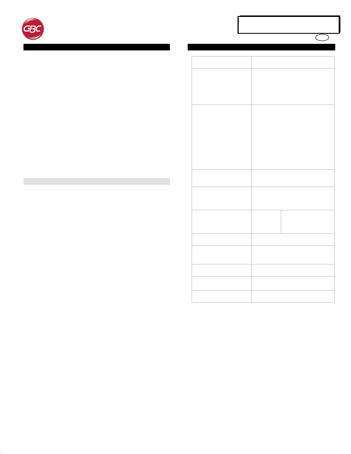
3. BINDER G1 SPECIFICATIONS 4
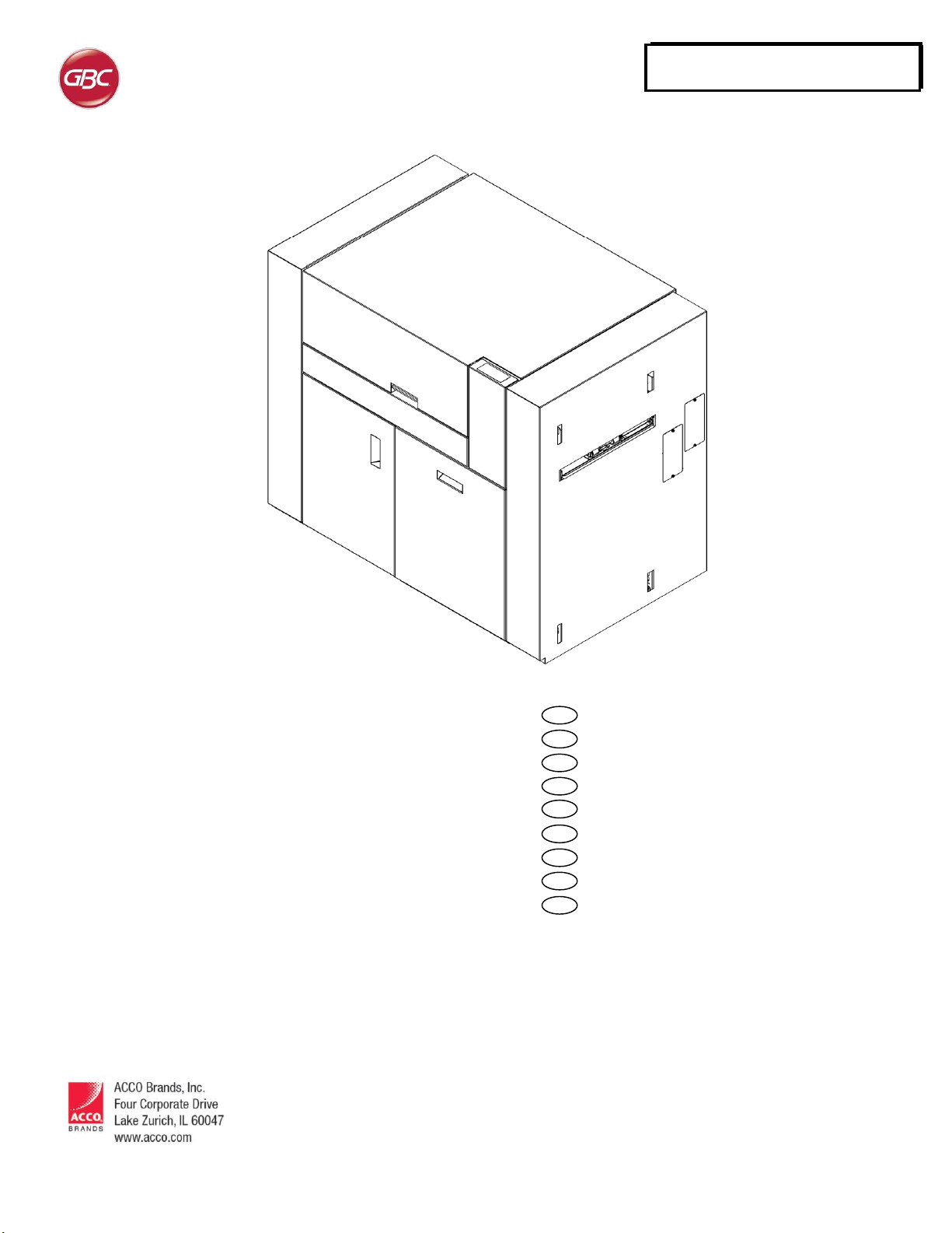
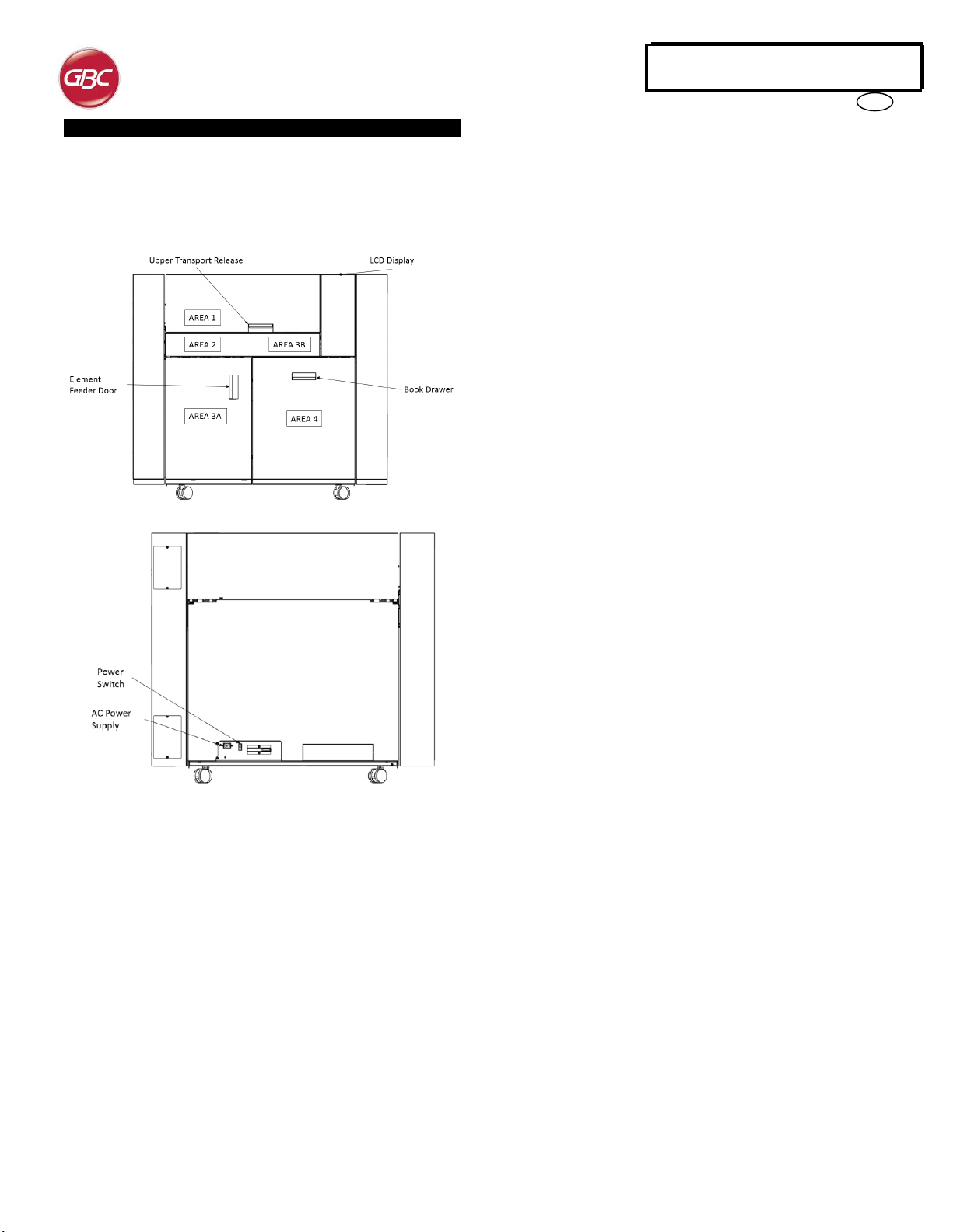
4. BINDER G1 OVERVIEW 5
5. BINDER G1 DIES FOR PUNCH G2 6
6. QUICK START GUIDE 6
7. USER OPERATIONS 6
8. USERDISPLAY 13
9. PROBLEM SOLVING 14
10. SUPPLY INFORMATION 18
11. LCD JAM CODES 19
1. SAFETY INSTRUCTIONS
THE SAFETY OF YOU AND OTHERS IS VERY IMPORTANT TO GBC.
IMPORTANT SAFETY MESSAGES AND INFORMATION ARE
CONTAINED IN THIS MANUAL AS WELL AS ON THE MACHINE
ITSELF. PLEASE MAKE SURE YOU CAREFULLY READ AND
UNDERSTAND ALL OF THESE BEFORE OPERATING THE
MACHINE.
THE SAFETY ALERT SYMBOL PRECEDES EACH SAFETY
MESSAGE IN THIS OPERATION INSTRUCTIONS
MANUAL. THIS SYMBOL INDICATES A POTENTIAL
PERSONAL SAFETY HAZARD THAT COULD HURT YOU
OR OTHERS.
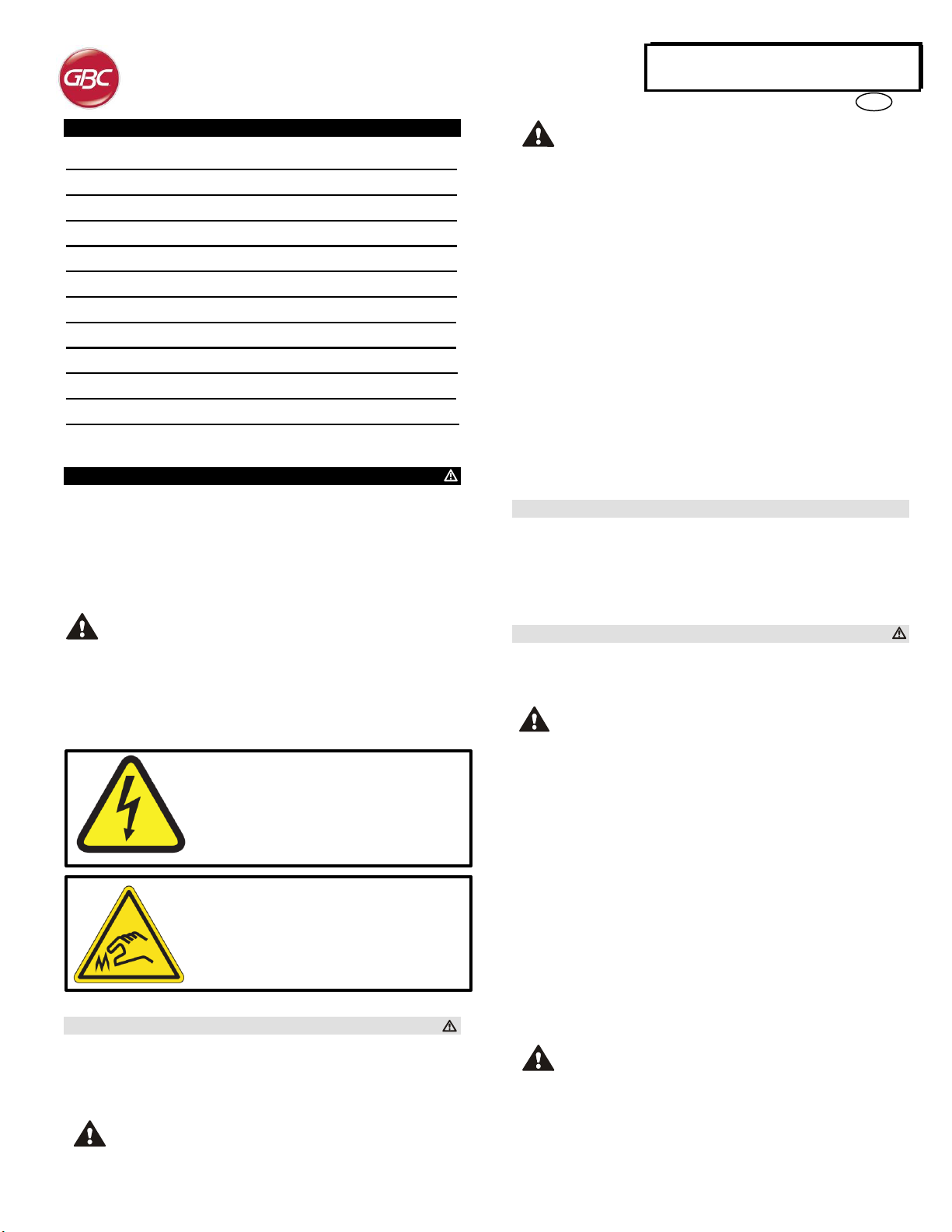
THE FOLLOWING PICTORIALS ARE FOUND ON THE BINDER G1:
This safety symbol means that you might get
seriously hurt or killed if you open the product
and expose yourself to hazardous voltage.
NEVER remove the screwed on covers.
ALWAYS refer service requirements to
qualified service personnel.
This safety symbol means that you may get cut
if you touch the knife positioned behind the
cover it is affixed to. Do not remove this cover
or place fingers behind it.
Important safeguards
Use the BINDER G1 only for its intended purpose of creating bound
books according to the indicated specifications.
Retain this Operation Instructions manual for future use.
CAUTION: THE PRINTER ON/OFF SWITCH DOES NOT
CUT OFF POWER FROM THE BINDER G1.
CAUTION: THE BINDER G1 ON/OFF SWITCH DOES NOT
CUT OFF POWER FROM THE PRINTER.
The BINDER G1 must be connected to a supply voltage
corresponding to the electrical rating of the machine operation
instructions (also listed on the serial number label).
The grounding plug is a safety feature and will only fit into the
proper grounding-type power outlet. If you are unable to insert the
plug into an outlet, contact a qualified electrician to have a suitable
outlet installed.
Do not alter the plug on the end of the cordset (if provided) of the
BINDER G1. It is provided for your safety.
Unplug the BINDER G1 before moving the machine machine or
whenever the machine is not in use for an extended period of time.
Do not operate the BINDER G1 if the machine has a damaged
power supply cord or plug. Do not operate the machine after any
malfunction. Do not operate the machine in case of liquid spills, or
if the machine has been damaged in any other way.
Do not overload electrical outlets beyond their capacity. To do so
may result in fire or electrical shock.
Cleaning
You may clean the exterior of the BINDER G1 using a soft, damp
cloth.
Do not use detergents or solvents as damage to the machine may
occur.
Safety messages
Do not attempt to service your BINDER G1 yourself. Contact an
authorized service representative for any required repairs or major
maintenance for your BINDER G1.
DO NOT REMOVE THE MACHINE’S COVER.
There are NO user-serviceable parts inside the machine. In order to
avoid potential personal injury and/or damage to property or the machine
itself, do not remove the machine’s cover.
FCC NOTE
This equipment has been tested and found to comply with the limits for
a Class A digital device, pursuant to Part 15 of the FCC Rules. These
limits are designed to provide reasonable protection against harmful
interference when the equipment is operated in a commercial
environment.
This equipment generates, uses, andcan radiate radio frequencyenergy
and, if not installed and used in accordance with the Operation Manual,
may cause harmful interference with radio communications. Operation
of this equipment in a residential area is likely to cause harmful
interference in which case the user will be required to correct the
interference at his/her own expense.
CAN ICES-3 (A)/NMB-3(A)
CAUTION: ANY MODIFICATIONS MADE TO THIS DEVICE
THAT ARE NOT APPROVED BY GBC MAY VOID THE
AUTHOIRITY GRANTED TO THE USER BY THE FCC
AND/OR INDUSTRY CANADA TO OPERATE THIS
EQUIPMENT.

4
GB
WIRE BINDER G1
2. INTRODUCTION
Thank you for purchasing the GBC WIRE BINDER G1. BINDER G1 is
the first fully automated inline binding system using traditional twin-loop
wire. Your BINDER G1 offers a variety of different twin loop wire
supplies, allowing the user to select the appropriate loop diameter and
color for the application.
The BINDER G1 is an innovative solution for twin loop binding and offers
the following design features:
Combines printing, punching, collating, and twin loop binding into
one integrated process.
Create professionally bound documents as quickly and easily as
they can be printed.
Wire binding creates strong, durable documents combined with an
attractive and professional appearance.
Saves significant time and cost compared to offline production.
The GBC PUNCH G2 is used to punch holes in each sheet prior to
binding. BINDER G1 die 7714915 or 7714916 must be installed in
the punch prior to operating BINDER G1.
Duty Cycle and Product Positioning Update
The BINDER G1 provides a flexible, cost effective binding solution for
light to medium level book bindingenvironments. For customers that run
continuous binding for long runs of over 4 hours, performance may vary
or degrade due to a wide range of media weights and environmental
conditions that can occur.
AMPV - Recommended 300,000 sheets OR 7,500 books average
monthly print volume (A4/letter).
3. BINDER G1 SPECIFICATIONS
Speed
Up to 144 sheets per minute
Bind Sheet Size and
Edge
LEF- Long Edge Feed
US Sizes
LTR LEF
ISO sizes
A4 LEF
Paper Stock
Plain: 75gsm - 300gsm
(20# bond to 110# cover)
Coated: 120gsm - 300gsm
(32# bond to 110# cover)
Covers: 176gsm –300gsm
Clear Cover: 7mil
(Clear Covers should only be used for
Front cover and not have print on it)
Paper Bypass Mode
Sheet size
Paper sizes and stocks same as
printer
Power Supply
115V, 60Hz, Single Phase
230V, 50Hz, Single Phase
Electrical
Amps and
Frequency
115V; 2.8A; 60Hz
230V; 1.4A; 50Hz
Safety Certification
cULus, CE
Dimensions
L: 29"; W: 47"; H: 40"
L: 75cm; W: 119cm; H: 102cm
Weight
231.5 kg (510 lbs)
Shipping Weight
291.5 kg (640 lbs)
Manufactured
Assembled in Taiwan

5
GB
WIRE BINDER G1
4. BINDER G1 OVERVIEW
The picture below shows an overview of the BINDER G1 system. Key
User Interface locations are identified. Functional areas are identified to
aid the user in troubleshooting. A jam can be categorized by identifying
where in the BINDER G1 the jam occurs.
BINDER G1 Overview
1. Area 1
This refers to the area of the BINDER G1 where sheets are fed in
and are eitherbypassed throughthe BINDER G1, orredirected into
the BINDER G1 for binding
2. Area 2
Refers to the area of the BINDER G1 where sheets are transferred
onto the twin loop wire for binding.
3. Area 3a
Refers to the area of the BINDER G1 where twin loop wire is fed
off the supply spool and cut to length for binding. Area 3 primarily
refers to wire feed, not paper stacking.
4. Area 3b
Refers to the area of the BINDER G1 where the closer and holder
are located. The closer compresses the open binding element to
finish the book. The Holder holds the element while sheets stack.
5. Area 4
Refers to the area of the BINDER G1 where bound books are
stacked.
6. Book Drawer
Pulling the Book Drawer handle will allow the user to access the
completed book stack for removal. The book drawer is only to be
opened when the printer is in standby.
7. Element Feeder Door
Open the door and release the Element Feeder tray to access the
twin loop supply spool. The element feeder door is only to be
opened when the printer is in standby.
8. Upper Transport Release
Release the latch and raise the lid to open the upper section of the
bypass panel. The lower bypass panel can also be raised, by lifting
the handle. Access this area of the machine for jam clearance.
9. LCD Display
The LCD will provide key information about the system, and also
allow the user to access settings on the BINDER G1.
10. AC Power Supply
Location for the power supply cord. Use only the cord provided.
11. Power Switch
Use to turn off power to the BINDER G1 during service, or if the
BINDER G1 will not be used for a long period of time.

6
GB
WIRE BINDER G1
5. BINDER G1 DIES
Prior to Operation of the BINDER G1, a BINDER G1 die set must be
installed into the PUNCH G2. BINDER G1 will not function unless
one of the die sets listed below is installed.
Die Set Details
A die set from the following list must be used. Refer to Section 10 of this
document for further details.
Die, eWire, 3:1, Round
7714915
Die, eWire, 3:1, Square
7714916
Punched Hole Quality
Prior to operating the BINDER G1 for the first time, or whenever a die
set is changed, perform the hole quality check outlined in Section 9 B.
6. QUICK START GUIDE
BINDER G1 must be connected to AC power and the rear ON/OFF
switch should be ON to enable any feature of the machine.
A spool of the correct size twin loop wire must be installed before
running a bind job. See Section 7 B for details on loading twin
loop spools into the BINDER G1
Ensure that the book drawer in area 4 is set to the size paper
you intend to use, shown below.
Check that the PUNCH G2 has a BINDER G1 die as detailed in
Section 5.
Do not open doors while the machine is operating. The current
job will not resume if any BINDER G1 doors are opened while
“RUNNING BINDING” OR “PAUSED” is displayed on the LCD.
When binding is not directed the machine will operate in bypass mode.
Layout of BINDER G1 LCD User Interface
7. USER OPERATIONS
A. Removing Supply Spool from the Machine:
Supply spools can be removed from the machine before they are
empty to be stored for future use.
B. Installing a New Supply Spool into the Machine:
BINDER G1 offers a variety of different twin loop wire options,
depending on the requirements of your job. Load a new wire supply
spool if a different size or color of binding is required, or when the
spool is empty.
C. Supply Spool Storage:
The twin loop wire supply spools should always be stored
according to the guidelines listed to prevent damage.
D. Emptying the Book Drawer:
Empty the book drawer to remove your bound books.
E. Clearing Jams:
How to clear paper or wire jams.
UP
DOWN
OK

7
GB
WIRE BINDER G1
A. Removing Supply Spool from the Machine:
WARNING: POSSIBLE PINCH POINT HAZARD. WHEN
INSTALLING OR REMOVING SUPPLY SPOOLS IN YOUR
BINDER G1, ALWAYS KEEP FINGERS AND OTHER BODY
AWAY FROM MOVING PARTS AND SHARP EDGES.
FAILURE TO FOLLOW THESE PRECAUTIONS MAY
RESULT IN INJURY.
When the ADD ELEMENTS message appears on the LCD,
opening and closing the Element Feeder Door will remove this
message. It is recommended to replace the spool immediately
when this message appears to prevent a jam condition.
Step 1: Stop the printer/copier.
Step 2: Open the Element Feeder Door
Step 3: Slide the feeder drawer out from the machine by pulling on
the handle.
Step 4: Turn the Knob
counterclockwise to release the
wire loose end from the Element
Feeder.
Note: If the wire end is past the
knife area, cut the excess before
turning the knob. Refer to section
7 E Area 3a
Step 5: Lift slack wire from the
metal wire guide surface and
place it against the magnetic
catch. This will hold wire out of
the way during replacement.
Step 6: Turn the rewind spool
counterclockwise to generate
slack in the carrier paper.
Step 7: Lift the metal wire
guide on the shield and pull the
carrier paper out from the shield.
Step 8: Remove the Element
Shield by pulling on the handle
and set it aside.
Step 9: Rewind the spool
counterclockwise to take the
excess slack from the wire and
the paper.
Step 10: Take the wire off the
magnet and place it on the
empty carrier paper you
rewound in Step 9. Pull the wire
toward the rewind spool making
sure to take up all of the slack.
Ensure that the wire you are
placing back on the spool is
contained in the paper you are
rewinding and does not interfere
with the other rows of wire
See Section 9 B for more
details.
Step 11: Secure the wire using
a magnet as shown. Repeat
steps 6 and 9 until all the wire is
on the spool
Step 12: Secure the wire rows
on the spool at the end of the
lose wire using the 2nd magnet
strip, then move the first magnet
strip you placed as shown here.
Place the magnets across rows
of wire so that the loose end of
wire is secured to the wound
rows. The magnets prevents the
wire from slipping when the
spool is removed.
Step 13: Tear the carrier paper
where it leaves the rewind
spool. Your carrier paper should
extend about 12 inches (30 cm)
beyond the loose end of your
wire.

8
GB
WIRE BINDER G1
Step 14: Unscrew the spool
retainer. Turn the knob
counterclockwise to loosen and
remove the cap. Set the cap
aside.
Step 15: Remove the spool from
the machine. Pull the spool
straight away from the machine
to slide it off the spindle. Properly
store the spool for future use.
Refer to Section 4 C for
guidelines on spool storage.
Note that the flexible magnet
must remain in place at all times
to prevent slipping of wire.
Step 16: To remove the rewind
spool from the feed spindle, push
the hub in and turn it clockwise.
Remove the excess paper by
sliding it off the hub.
Note: If the rewind spool is full of
paper, it may be difficult to
remove. The spool must be
pressed in firmly before rotating
to disengage the pin.
Step 17: Reinstall the empty paper feed hub to the machine. Slide it
onto the feed hub shaft and rotate counter clockwise until it latches in
place.
Step 18: Open the top cover and
identify the wire Holder. Check if
there is a cut length of wire onthe
Holder (long boxed section). If
there is, remove it by pressing
the Holder release (small boxed
sections) and removing the wire.
Step 19: If a new spool is to be installed, follow the steps in the
section, Section 7 B.
Step 20: If no new Supply Spool is to be installed, reinstall the
Element Shield and the Spool Retainer then slide the Element Feeder
Drawer into the machine. Ensure that the drawer is pushed in fully or
the message “Push Feeder In” will appear on the LCD. Close the
Element Feeder Door.
B. Installing a New Supply Spool Into the Machine:
Step 1: Stop the printer/copier.
Step 2: Open the Element Feeder Door.
Step 3: Slide the feeder drawer out from the machine by pulling on
the handle.
Step 4: If applicable, follow the instructions in Section A to remove
the previously installed element spool.
Step 5: Remove the wire
shield. Pull on the wire shield
handle to remove the entire
shield, and place the shield
safely on top of the element
feeder.
Step 6: Remove the spool retainer from the spindle. Turn the knob
counter clockwise until the cap can be removed, and set it aside.
Step 7: Remove the Supply
Spool from its carton and remove
the plastic shrink wrap.
Method 1: Remove the plastic by
cutting across using scissors.
Caution: Do not cut the carrier
paper or wire when cutting the
plastic, doing so may ruin the
spool.
Note: Do not remove the
cardboard retainer at this point.
The wire will unwind if it is not
secured throughout the process
and may lead to jams.
Method 2:With the plastic still on
the Supply Spool proceed to
Steps 8 & 9 before slowly
unwinding it.
Step 8: Install the spool by
sliding the spool onto the hub.
The circular barcode label must
face towards the inside of the
machine. The product
description label on the hub must
face out.

9
GB
WIRE BINDER G1
Step 9: Secure the spool by
using the spool retainer. Turn the
knob clockwise to thread the cap
into the spindle until spool is
secure. Do not over tighten.
Step 10: Gently remove the flat
cardboard spacer that is used to
secure the wire during shipment.
Before removing the spacer,
check that the flexible magnet is
installed to secure the wire.
Step 11: Pull the wire and paper
away from the spool and hold
them both in one hand.With your
free hand install the wire shield.
Step 12: While still holding the
carrier paper, use the magnetic
catch to hold the wire.
Step 13: Lift the metal guide of
the shield and slide the carrier
paper between it and the lower
bars.
Step 14: Attach the end of the
carrier paper to the rewind spool.
Leave 1-2in (2.5-5cm) of excess
and fold that back on top of the
metal clip.
Step 15: Turn the rewind spool
clockwise until you have enough
wire to reach the blue wire guide.
Slide the wire onto the plastic
wire guide and feed it into the
plastic sprocket. Use the knob to
manually turn the plastic
sprocket and aid wire installation.
Step 16: Adjust the wire end
position by using the knob
attached to the wire feed
sprocket. The wire end should
line up in the window on the
blade guard. The wire end
should line up with the transition
line between the blue wire guide
and the grey anvil.
Step 17: Proper installation of
the spool is shown. Wire loose
end is fed around the guide and
positioned properly on the wire
feed sprocket. Paper loose end
is secured to the paper feed hub.
Once installed properly, rotate
the paper rewind spool clock-
wise until the wire makes contact
with the sensor flap under the
spool.
Step 18: Slide the wire feeder drawer back into the machine.
Ensure that the drawer is pushed fully back or the message “Push
Feeder In” will appear on the LCD
Step 19: Close the wire feeder door.

10
GB
WIRE BINDER G1
Post Spool Installation Review:
Confirm all the following:
Is the spool secured to the Element Feeder by the holder cap,
with the circular bar code facing in as shown in Section 7 B
Step 9?
Is the wire fed onto the Element Feeder track, with the end
located just before the knife as shown in Section 7 B Step 16?
Is the wire shield in place, with one row of wire resting loosely
on top of it?
Is there one row slack wire below the spool?
Is the end of the paper feed secured to the rewind hub as
shown in Section 7 B Step 14?
Is any excess wire removed from the Element Feeder? No
wire should be present past the knife as shown in Section 7 B
Step 14.
Open the top cover. Is any excess wire present on the Holder
as shown in Section 7 A Step 18?
Add Elements Message:
The message “ADD ELEMENTS” will be displayed on the LCD when the
eWire detects it is low on elements. When this message appears the
spool must be replaced.
There will be a length of wire remaining on the spool when this message
appears. This extra length is left to ensure the final books bind properly.
This wire is meant to be discarded with the empty spool. Continuing to
operate the eWire after this message has been displayed will result in
unhooked sheets and unbound books.
Note: Opening and closing the element door will remove this message. It
is recommended to replace the spool immediately when this message
appears to prevent a jam condition.
C. Storing Supply Spools:
Supply spools shouldalways be stored vertically. Flat storage may result
in twisted or tangled wires. Always handle partially empty spools very
carefully.
Use the flexible magnet strip to secure loose ends of wire whenever a
partially used spool is removed from the machine.
If spools are to be stored in their cartons, cartons must be stacked
vertically. Refer to markings on the side of the package.
Examples of Proper Spool Storage:
Example of improper spool storage:
Do not store themagnet strips onthe inside of the element feeder drawer
when not in use, this can cause wire jams. Store the magnets as shown
below on the element feeder drawer or away from the machine. When
storying them on the element feeder, ensure that they are completely on
the flat face of the drawer and are not near the spool.
Example of improper magnet storage:

11
GB
WIRE BINDER G1
D. Emptying the Book Drawer:
Step 1: Stop the printer/copier.
Do not open thedoor until current
operation is complete.
Step 2: Open the BINDER G1
Book Drawer using the handle.
Step 3: Slide the Book Drawer
Tray out of the BINDER G1.
Remove the stack of books from
the Tray. Note that all books
must be removed at once, do not
leave the tray partially full.
Step 4: Ensure the Tray is empty
and that no debris is present in
the Tray area. Close the Book
Drawer Door firmly and resume
operation.
Bound Book Drawer Capacity
Element Size
Book capacity*
A
35
B
35
C
35
D
30
E
25
* Book drawer capacity may be lower when binding books with front and
rear covers less than 216gsm.
For optimal book stacking, it is recommended that books contain front
and back covers and be no smaller than 5 sheets plus 2 covers.
Books will be bound with the front cover on the bottom of the stack, to
complete the book this cover must be flipped to the front.
E. Clearing Jams:
When a jam occurs in the BINDER G1, identify
the location of the jam, and clear the excess
paper, starting with Area 1 and proceeding to
Area 2, 3, and 4. After clearing any jam,
return to area 3b and remove any wire that
may be present
Area
Description
Area 1 –Bypass Paper Jam
If paper is jammed in Area
1, raise the top cover and
remove the jammed paper.
Raise the lower transport by
lifting on the handle.
Remove any paper trapped
between the bypass region
and the stacking region.
Area 2 –Bypass Transfer or Stacking
Area Paper Jam
If paper is jammed in Area
2, raise the top cover and
the lower bypass by lifting
the handle to access the
stacking region. Raise the
vacuum stacker handle to
remove paper from the
stacking area. Sheets may
be partially hooked onto the
wire segment.
If loose sheets are left in the
stacking area, remove the
incomplete book from the
book drawer, after
removing these sheets.

12
GB
WIRE BINDER G1
Area 3a–Twin Loop Wire Feed Jam
Open the front door and
slide out the drawer using
the handle provided. Check
if the rewind paper from the
spool has been cut or
damaged. Check that the
wire feed from the spool has
enough slack. Check for any
excess wire in the Feeder
area.
No wire should be present
beyond the knifearea. If wire
is present past the knife, use
the wire cutters provided to
cut and remove it, then
positionthe wire asshown in
Section 7 B Step 11.
Remove any excess wire
past the knife by turning the
belt knob clockwise. Do not
pull wire from belt teeth
Caution
When cutting excess wire, cut it just before the knife. Lift the wire off of
the blue plastic nose. Do not allow the wire cutters to contact the plastic
nose or it can become damaged.
If it is necessary to remove
a piece of wire from under
the knife cover, first try
turning the element feed
knob counter clockwise, do
not reach under the cover
with your fingers. If you
cannot remove the wire
using the knob, use the wire
cutters provided to grab the
wire and pull it free.
Area 4 –Book Tray Jam
Open the Book Tray by
pulling on the door handle.
If the book tray is full,
remove all books from the
elevator and close the door
firmly. Check for any debris
or loose paper in the book
tray area.
Area 3b –Clear Remaining Wire
First follow the steps above
to remove all paper jams
and wire feed jams. After
opening the Area 1 cover
and closing it, the holder
should retract and become
accessible. Before
resuming operation, check
if a segment of wire has
been cut and is still in the
machine.
To remove a wire length
from the holder, with one
hand press in the green tab
to disengage the wire and
with the other hand pull the
wire free.
Sharp Edge!
Cut finger with contact
Do not remove cover or place fingers behind it.

13
GB
WIRE BINDER G1
8. USER DISPLAY
Located on the front of the BINDER G1 is a user interactive LCD panel
that provides Messages, Settings and Information relating to the
functions of the binder.
Messages on the LCD Panel
1. Ready Bypass
BINDER G1 is ready to bypass, sheets will pass through the
machine.
2. Ready to Bind
BINDER G1 is ready to process a binding job, all sheets through
the unit will be stacked and bound.
3. Running Bypass
This message will be displayed when Bypass mode is in operation.
4. Running Binding
This is displayed when Bindmode is in operation. The book drawer
capacity will be displayed as a percentage on the right of screen. If
a door of the BINDER G1 is opened during binding, the job will not
resume.
5. Book Tray Full
When the book tray is full or near full, the Tray Full message will be
shown.
6. Close Tray
When the book tray is removed or not fully inserted into the
BINDER G1 unit, this message will be displayed.
7. Close Door
When the Front door is open or not completely closed this message
will be displayed.
8. Close Cover
When the top cover is open or not completely closed this message
will be displayed.
9. Add Elements
When the supply of elements is low, or the spool is missing, the
add elements message is displayed. See Section 7 B for more
details.
10. Paused
When there is a non-BINDERG1 stoppage in the line of equipment
this message will be displayed. If a door of the BINDER G1 is
opened during a pause, the job will not resume.
11. Jam Code
The jam code will appear when there is a jam in the machine
along with the area the jam is located. Refer to Section 7 E for
instructions on clearing jams and Section 11 for details on each
jam
12. Push Feeder In
This message appears when the element feeder door is closed
but the drawer is not fully pushed in. Opening the door, pushing
the drawer fully in, and closing the door will remove this message.
Changing the Settings on the LCD panel
The User Interface is navigated using the Up and Down arrows next
to the LCD. To change any setting below press OK while it is on
the display and use the arrows to change the setting. After
changing any setting press OK and exit the settings mode.
1. Closing
Use this option to change the closing depth for the twin loop
wire. Offset from -5 to +5 is available and will apply only to the
wire size selected. Use this option to correct for binding that is
over- or under-closed. Refer to Section 9 F for more details.
2. Alignment
Use this option to correct for sheet offset coming into the
BINDER G1. Refer to Section 9 E for more details.
3. Deflector
Use this option to correct for the timing of the deflector. Refer
to Section 9 E for more details.
4. Language
Use this option to change the language displayed on the LCD
screen.
Displaying Information on the LCD Panel
1. Wire Size
Displays the wire size currently selected. Also shown on the
home screen.
2. Counts
Displays the number of books and sheets that have been
processed by the BINDER G1.
3. Firmware
This displays the current level of firmware of BINDER G1.

14
GB
WIRE BINDER G1
9. PROBLEM SOLVING
A. Common Problems:
Problem
Probable Cause
No power, No
Operation
Power cord not attached to back of machine or
not properly plugged into the wall.
Power On/Off Switch not activated
Close Door/Close
Tray/Close Cover
message appears
Ensure that the doors and cover are properly
closed and latched. Press the door or cover
firmly into place. If message appears
repeatedly, adjust the Interlock flag.
Twin-Loop wire
jamming
repeatedly
Avoid damage to the spool by taking care
during storage and loading.
Remove the excess wire and re-feed wire into
the element feed module. Follow the
installation instructions in Section 4.
If necessary, remove a length of wire from the
spool and reinstall the spool.
Sheets jamming
repeatedly on the
Stacking area
(Area 2)
J202, J203, J244
Confirm that an appropriate BINDER G1 die is
installed on the PUNCH G2. Using an unbound
sheet, confirm the punched hole accuracy
using the guidelines in Section 9 C-D. If the
accuracy of the punched holes is not in spec,
make adjustments to the PUNCH G2 alignment
settings. If problem persists, see Section 9 E
Wire jamming in
feeder. (Area 3a)
J361
J361 jams on the BINDER G1 may be caused
by dust on the film cover on the element sensor
(S22). Clean the film by wiping a dry cloth
across the film covering the element sensor
shown below.
J361 jams can also be caused by the wire end
being positioned incorrectly when installing a
spool. Refer to Section 7 B step 16.
Broken carrier
paper
Broken carrier
paper (continued)
If the carrier paper between the wire spool and
rewind spool breaks, rotate the wire spool
clockwise until you have enough paper to reach
the rewind spool, then follow the spool
installation steps starting on step 12. You may
need to cut off the excess wire if there is too
much slack in it.
Alternatively, you may be able to repair the
carrier paper when it tears. Unwind the rewind
spool until you have enough slack to overlap 2
inches (50mm) of the paper ends. Wrap the
overlapped section in packaging tape and
follow the spool installation steps starting on
step 12.
Wire failing to
trigger slack
sensor. (Area 3a)
J320
J320 jams on the BINDER G1 may be caused
by the carrierpaper between the wire spool and
rewind spool breaking or by becoming
entangled on the wire. Refer to Section 7 B
steps 1-5 and steps 11-19 for reinstalling the
spool. Note: It may be necessary to trim off
excess wire if the length of carrier paper is not
sufficient to reach the rewind spool or if the wire
has been damaged by stretching.
J320 jams on the BINDER G1 may also be
caused by debris collecting on the element
slack sensor and restricting its motion. Clear
the debris with a cloth or vacuum.
Full Rewind Spool
J320
J320 jams can occur when the rewind spool
becomes too full. The rewind spool has a
window cut into it. When paper reaches this
window, cut the paper where it leave the rewind
spool and perform steps 16-17 in Section 7 A
to empty the hub and then reattach the cut end
to the now empty spool

15
GB
WIRE BINDER G1
B. Common Spool Problems
The wire on the spool may become damaged when not properly
handled. In this section there are examples of common issues you may
see on a spool.
Cutting Wire
When part of the spoolof wire is damaged, it must be removedusing the
wire cutters provide. Theyare located on theinside ofthe element feeder
door. When cutting the wire, cut the wire in the center of the larger loop
as shown below. Excess paper can then be removed, leaving 12 inches
(30 cm) past the new end of the wire.
Stretched Wire
Wire can become stretched when installing or removing a spool from the
machine, it may also become stretched due to wire jams. If any length
of wire is stretched like shown below, use the wire cutters provided to
cut that section off. Wire is considered stretched if the loops are no
longer parallel to each other. The wire outlined in red is an example of
stretched wire.
Crushed Wire
Wire can become crushed when the spool is miss handled. Below is an
example of a crushed length of wire. Crushed wire must be cut off and
discarded.
Tangled Wire
If the spool is stored without the wire properly secured with the magnet
strips, the wire may become entangled. This can be fixed by carefully
separating the entangled rows. Once untangled, check that no other
damage is present before using this spool.
Loose Element
The BINDER G1 will prompt the user to clear extra elements from 3b
after a stoppage occurs. If this is not done the element may fall into the
element feeder area and cause a wire jam to occur. The wire could fall
on top of the spool as shown below. If this occurs, carefully remove the
loose element and check the spool for damage.
The wire may fall to the bottom of the element drawer. If this occurs
remove the wire and check for adouble loop as discussed in this section.

16
GB
WIRE BINDER G1
Double Loop
A double loop occurs when a row of wire other than the one being fed
has slack in it. This will result in a J320 wire jam code.
To resolve this, follow the slack wire to the top of the spool and gently
pull the slack clockwise. This will transfer the slack to the next row of
wire, repeat this until the all the slack is in the last row being fed.
C. Troubleshooting:
This section will lay out the troubleshooting steps for when sheets are
not being hooked on the twin loop wire tips. In some cases, it will also
create a Jam code. J202, J203 and J244 are the most likely Jam to be
caused as a result of poor hooking. Before changing any settings on
the BINDER G1 or Punch, review each trouble shooting step below.
Verify that the BINDER G1 is properly docked to the
upstream device and confirm that there is no misalignment
between the devices.
Check that printed sheets do not have excess curl. Flat
paper will hook more reliably when binding books. Make
efforts to reduce curl to the minimum possible. Review the
printer manual to reduce this if present. Example of curled
sheet below.
Inspect the element spool for damage, if the wire is damaged
removed the damaged length of wire or replace the spool
with one of the same size.
Verify the proper element size is being used for the amount
of sheets in the book being run. Refer to the chart in Section
10
Examine your unhooked sheet for damage around the holes,
this can manifest as tears or imprints. If any is present,
proceed to the Deflector and Alignment Adjustment
When binding with paper of 300 gsm with grain orientation in
the direction of paper flow, paper jams may occur depending
on the stiffness of the media. Using a different, less rigid,
cover media may remove the problem.
D. Punch Hole Quality:
If the punch upstream of the BINDER G1 is not punching holes within
specification, the binding capabilities of the BINDER G1 will be reduced,
resulting in jams and unhooked sheets.
1. Using the Hole Position Tool provided, confirm the backgage depth
and alignment of a single punched sheet. To use the tool, take a
punched, unbound sheet of paper and align it with the either the
“LTR” or “A4” corner, depending on the paper size. The black lines
should faintly visible behind the sheet, when the punch is properly
aligned, the black circles will be evenly visible around all of the
punch holes.
2. If the holes do not align with the outlines on the tool, refer to the
PUNCH G2 user manual to make adjustments to the hole position.

17
GB
WIRE BINDER G1
E. BINDER G1 Deflector and Alignment Adjustment
If all the above check out and there are still sheets left in the stacking
area after binding, the deflector timing or alignment may be off. When
the deflector timing or alignment setting on the BINDER G1 are off, the
deflector will push sheets down onto the open wire when the holes are
not aligned with the wire. This will result in unhooked sheets and
damage to the paper around the holes. Examining these unhooked
sheets will show you the adjustments you need to make.
Remove the unhooked sheets from the tray and hold them with the tray
facing side up. Look closely at each hole for any damage. When the
damage is between two holes it means that the alignment adjustment
is off. If the damage is next to a hole it means the deflector timing is off.
Below are examples of both and instructions on how to correct them. It
is possible for both your deflector and alignment to need adjustment, if
this happens your markings will be offset diagonally from the holes.
Note: Before changing your deflector or alignment settings, record
what they are. If you are unable to fix your unhooking issue, return the
values to their original settings.
Deflector Adjustment
When imprints from the element appear between the hole and the trail
edge of the sheet, the deflector value needs to be decreased. Measure
the distance from this mark to the center of the hole and decrease your
deflector value by that much.
When imprints from the element on the lead edge of the hole, the
deflector value needs to be increased. Measure the distance from this
mark to the center of the hole and increase your deflector value by that
much.
After adjusting your deflector setting, run a book to test out the new
deflector timing value. If sheets are still unhooking, remeasure the hook
mark and adjust accordingly. Repeat this process until you no longer
have marks on the trail and lead edge of the hole.
Alignment Adjustment
When the imprint appears on the left side of the hole (when looking at
the tray down side with in the orientation shown above) the alignment
values you needs to be increase. Measure the distance from the center
of the mark to the center of the hole and increase your alignment value
by this amount.
When the imprint appears on the right side of the hole (when looking at
the tray down side with in the orientation shown above) the alignment
values you needs to be decreased. Measure the distance from the
center of the mark to the center of the hole and decrease your alignment
value by this amount.
After adjusting your alignment setting, run a book to test out the new
alignment value. If sheets are still unhooking, remeasure the hook mark
and adjust accordingly. Repeat this process until you no longer have
marks between the holes.
If after performing these adjustments your sheets are still not hooking,
revert to your original recorded values and contact the service
department.

18
GB
WIRE BINDER G1
F. Element Closing:
A properly closed element is circular. It allows the pages to turn without
restricting the paper, while not allowing sheets to fall out of the binding.
Above is a diagram of a correctly closed element. The element is
considered under-closed if it is possible to pull a sheet out of the twin
loop binding by pulling on the end of the sheet. The element is
considered over-closed if the element is oval shaped. If the element is
under-closed increase the closer value in the LCD tree, decrease this
value instead if the element is over-closed. After changing the setting
run a new book and inspect its element.
10. SUPPLY INFORMATION
A. Supply Order Information
Twin loop wire supply for the BINDER G1 machine comes in 5 different
sizes and 3 different colors. In order to switch between size and colors
of twin loop wire, follow the instructions in Section 4. To re-order or
order new wire supply, refer to the table below.
Description
Reorder Number
eWire Spool, Element Size 'A', Black
7717962
eWire Spool, Element Size 'B', Black
7717963
eWire Spool, Element Size 'C', Black
7717964
eWire Spool, Element Size 'D', Black
7717965
eWire Spool, Element Size 'E', Black
7717966
eWire Spool, Element Size 'A', White
7717968
eWire Spool, Element Size 'B', White
7717969
eWire Spool, Element Size 'C', White
7717970
eWire Spool, Element Size 'D', White
7717971
eWire Spool, Element Size 'E', White
7717972
eWire Spool, Element Size 'A', Silver
7717974
eWire Spool, Element Size 'B', Silver
7717975
eWire Spool, Element Size 'C', Silver
7717976
eWire Spool, Element Size 'D', Silver
7717977
eWire Spool, Element Size 'E', Silver
7717978
Die Set Part Numbers:
Die, eWire, 3:1, Round
7714915
Die, eWire, 3:1, Square
7714916
Die Set Description:
Square Hole Die:
eWire; Square; 3 Holes per inch; Hole Size: 5mm x 5mm (0.197" x 0.197") (L x W); Center-to-Center Hole Spacing:
8.5mm (0.333")
Round Hole Die:
eWire; Round; 3 Holes per inch; Hole Size: 5.5mm (0.217") Diameter; Center-to-Center Hole Spacing: 8.5mm (0.335")
B. Book Capacity Information
Element
Size
Sheet
Capacity*
(75 gsm)
Max.
Document
Thickness
(mm)
Max Books Per
Spool†
Letter
A4
A
15-30
3
515
485
B
31-50
5
320
300
C
51-60
6
250
235
D
61-70
7
180
170
E
71-80
8
130
120
*Sheet capacity based on 20lb (75 gsm) paper. Subtract 10 sheets
(1mm) to accommodate covers.
†Max books per spool is the greatest number of books a spool can
produce if none is wasted during operation or set up.
1 34-A432-LTR
1 34-A432-LTR

19
GB
WIRE BINDER G1
11. LCD JAM CODES
When a jam occurs on the BINDER G1, a jam code will be displayed on
the LCD. Below is a list of all the jam codes that may appear. When
instructed to check an area, refer to that area in Section 7 E on clearing
jams. Many jam codes only require that the cover be opened and then
closed to allow the module to reposition itself.
Paper Jams
Jam
Code
Jam Description
Clearing
J101-
J152
A sheet is present in the paper
bypass
Clear sheets from Area 1
J202-
J203
A sheet is present in the paper
transport
Clear sheets from Area 2
Refer to Section 9 C-D
J244
Sheets are present in the paper
tray
Clear sheets from Area 2
Refer to Section 9 C-D
J260-
J261
A sheet is present in the paper
bypass
Clear sheets from Area 1
Wire Jams
Jam
Code
Jam Description
Clearing
J320
Element spool timeout
Check element spool in
Area 3a
J321-
J322
Element timeout
Check for fed element in
Area 3a
J323
Knife error
Check knife in Area 3a
J324-
J334
Element feeder position timeout
Open and close element
feeder door
J350
Spool empty and needs
replacement
Replace spool in Area 3a
J351
Element feeder position timeout
Open and close element
feeder door
J360-
J362
Element timeout
Check for fed element in
Area 3a
J363
Element feeder position timeout
Open and close element
feeder door
J364-
J365
Element timeout
Check for fed element in
Area 3a
J366-
J369
Element feeder position timeout
Open and close element
feeder door
Bind Jams
Jam
Code
Jam Description
Clearing
J370-
J377
Holder position timeout
Open and close element
feeder door
J379-
J380
Closer closing timeout
Open and close element
feeder door
J381
Closer position timeout
Open and close element
feeder door
J382-
J383
Closer closing timeout
Open and close element
feeder door
J384-
J393
Holder position timeout
Open and close element
feeder door
J394
Closer closing timeout
Open and close element
feeder door
J395
Holder position timeout
Open and close element
feeder door
J396
Closer closing timeout
Open and close element
feeder door
Book Jams
Jam Code
Jam Description
Clearing
J442
Book drawer position
timeout
Open and close book drawer
J443
Book drawer position
timeout
Open and close book drawer
Book
drawer full
Book drawer full
Empty book drawer
J451
Book drawer position
timeout
Open and close book drawer
J452
Book drawer open
during job
Close book drawer

20
F
WIRE BINDER G1
TABLE DES MATIÈRES
1. CONSIGNES DE SÉCURITÉ 20
2. INTRODUCTION 21
3. SPÉCIFICATIONS DU BINDER G1 21
4. PRÉSENTATION DU BINDER G1 22
5. MATRICES BINDER G1 POUR LA PUNCH G2 23
6. GUIDE DE DÉMARRAGE RAPIDE 23
7. OPÉRATIONS DE L'UTILISATEUR 23
8. AFFICHAGE DE L'UTILISATEUR 30
9. RÉSOLUTION DES PROBLÈMES 31
10. INFORMATIONS SUR L'ALIMENTATION -
BINDER G1 35
11. CODES DE BOURRAGE LCD 36
1. CONSIGNES DE SÉCURITÉ
VOTRE SÉCURITÉ ET CELLE DES AUTRES EST TRÈS
IMPORTANTE POUR GBC. DES MESSAGES ET DE L’INFORMATION
DE SÉCURITÉ SONT INCLUS DANS CE MANUEL AINSI QUE SURLA
MACHINE ELLE-MÊME. VEUILLEZ VOUS ASSURER QUE VOUS LES
AVEZ BIEN LUS ET BIEN COMPRIS AVANT D’UTILISER LA
MACHINE.
DANS CE MANUEL D’UTILISATION, VOUS TROUVEREZ
UN SYMBOLE D’AVERTISSEMENT EN REGARD DE
CHAQUE MESSAGE DE SÉCURITÉ. CE SYMBOLE
SIGNALE UN RISQUE POTENTIEL. VOUS POURRIEZ
VOUS BLESSER, BLESSER UN TIERS OU ENDOMMAGER
LE PRODUIT.
LES SIGLES SUIVANTS SE TROUVENT SUR LE BINDER G1 :
Ce symbole de sécurité signale qu'une décharge
électrique pourrait vous blesser gravement, voire
entraîner la mort si vous ouvrez la machine. Ne
retirez JAMAIS les couvercles vissés de la
machine. Faites TOUJOURS appel pour la
maintenance à un personnel qualifié.
Ce symbole de sécurité signifie que vous pouvez
vous couper si vous touchez le couteau placé
derrière le capot auquel il est fixé. Ne soulevez
pas ce capot et ne passez pas vos doigts derrière
ce dernier.
Consignes importantes
Utilisez BINDER G1 uniquement pour perforer le papier et les
couvertures conformément aux spécifications indiquées.
Gardez ce manuel d’utilisation à portée de main.
PRÉCAUTION: LE COMMUTATEUR MARCHE/ARRÊT DE
L'IMPRIMANTE NE COUPE PAS LE COURANT DU BINDER
G1.
PRÉCAUTION : LE BINDER G1 MARCHE/ARRÊT DE
L'IMPRIMANTE NE COUPE PAS LE COURANT DE
L'IMPRIMANTE.
La tension d’alimentation de BINDER G1 doit correspondre aux
caractéristiques électriques de la machine (elles sont indiquées sur
l’étiquette du numéro de série).
Une prise de terre est prévue par mesure de sécurité. Elle doit être
raccordée à une prise électrique prévue à cet effet. Si vous ne
parvenez pas à introduire la fiche dans la prise, faites appel à un
électricien qualifié pour qu’il installe une prise adéquate.
Ne modifiez pas la fiche située au bout du cordon d’alimentation de
BINDER G1 (si elle est fournie). Elle a été conçue pour votre
sécurité.
Débranchezle BINDER G1 avant de déplacer la machine ou encas
d’inutilisation prolongée.
N’utilisez pas BINDER G1 si le cordon ou la fiche d’alimentation de
la machine est endommagé. N’utilisez pas la machine après un
quelconque dysfonctionnement. Ne mettez pas la machine sous
tension si vous avez renversé un liquide ou si elle est endommagée
de quelque façon que ce soit.
Ne surchargez pas les prises électriques. Cela pourrait provoquer
un incendie ou une décharge électrique.
Nettoyage
Vous pouvez nettoyer la surface externe du BINDER G1 à l’aide
d’un chiffon doux et humide.
N’utilisez pas de détergent ou de solvants car vous pourriez
endommager la machine.
Messages de sécurité
Ne tentez pas de réparer votre BINDER G1 par vous-même. Contactez
un représentant agréé pour effectuer les réparations ou le gros entretien
de votre BINDER G1.
NE RETIREZ PAS LES COUVERCLES DE LA MACHINE.
La machine ne comporte AUCUNE pièce susceptible d'être réparée par
l'utilisateur. Pour éviter tout risque de blessure corporelle et/ou de dégât
sur le matériel ou la machine elle-même, ne pas retirer le couvercle de
la machine.
NOTE FCC
(LE PARAGRAPHE SUIVANT NE S’APPLIQUE QU’AUX MODÈLES
ALIMENTÉS PAR UN COURANT DE 115V 60Hz.)
Cet équipement a été testé et il satisfait aux normes relatives aux
appareils numériques de Classe A, conformément à la Partie 15 des
règles FCC. Ces limites ont été prévues pour garantir une protection
raisonnable contre les interférences nocives lors de l’utilisation de
l’équipement dans une zone de travail.
Cet équipement génère, utilise et irradie des ondes radio. Par
conséquent, si vous ne l’installez pas ou ne l’utilisez pas conformément
au manuel d’utilisation, vous risquez de provoquer des interferences
dans les communications par radio. L’utilisation de cet équipement dans
une zone habitée risque de provoquer des interférences. Dans ce cas,
vous devrez corriger ces interférences à vos
frais.
CAN ICES-3 (A)/NMB-3(A)
MISE EN GARDE : TOUTE MODIFICATION EFFECTUÉE
SUR CET APPAREIL QUI NE SERAIT PAS APPROUVÉE
PAR GBC PEUT ANNULER L'AUTORISATION ACCORDÉE
À L'UTILISATEUR PAR LA FCC ET/OU L'INDUSTRIE AU
CANADA D'UTILISER CET ÉQUIPEMENT.
Table of contents
Languages:
Other ACCO Brands Binding Machine manuals

ACCO Brands
ACCO Brands Rexel CWB406 User manual

ACCO Brands
ACCO Brands REXEL CB105 User manual

ACCO Brands
ACCO Brands GBC Ricoh StreamPunch Ultra User manual

ACCO Brands
ACCO Brands Rexel CWB406 User manual

ACCO Brands
ACCO Brands GBC C340 Comb Binder User manual

ACCO Brands
ACCO Brands GBC StreamPunch Ultra Administrator Guide