Acea RTCA SP Instrument User manual

RTCA SP Instrument
Operator’s Manual Version January 2013


3
Table of Content
Prologue 5
I. Revision History .................................................................................................................................................5
II. Contact Addresses ...........................................................................................................................................5
III. Declaration of Conformity............................................................................................................................6
IV. Warranty .................................................................................................................................................................6
V. Trademarks ...........................................................................................................................................................6
VI. Intended Use........................................................................................................................................................6
VII. License Statements for the Instrument................................................................................................7
VIII. Software License Agreement.....................................................................................................................7
IX. Preamble................................................................................................................................................................7
X. Use of the Instrument Operator’s Manual ..........................................................................................8
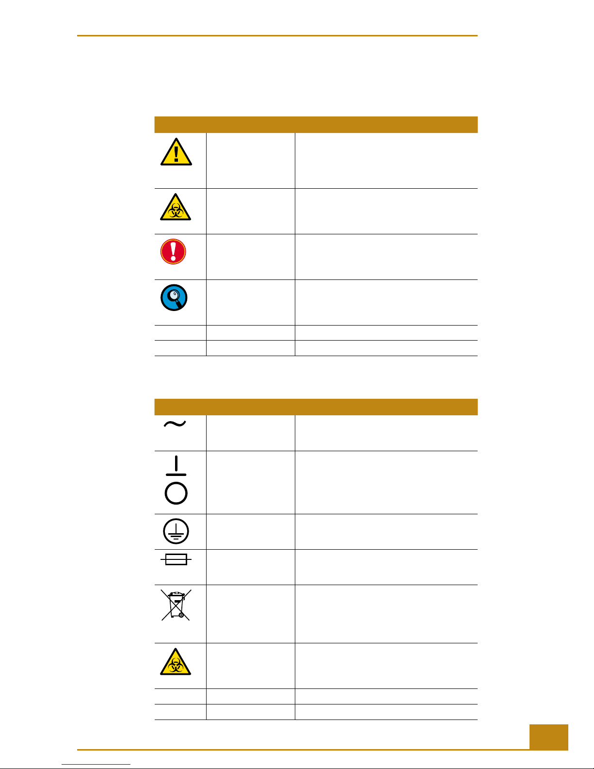
XI. Conventions Used in this Manual............................................................................................................8
XII. Warnings and Precautions........................................................................................................................ 10
XIII. Disposal of the Instrument ....................................................................................................................... 12
A Overview 13
1. Introduction....................................................................................................................................................... 13
1.1 RTCA SP Instrument ......................................................................................................................................... 14
2. Specifi cations of the Instrument ........................................................................................................... 17
2.1 Specifi cations of the RTCA Analyzer.......................................................................................................... 17
2.2 Specifi cations of the RTCA SP Station ...................................................................................................... 17
2.3 Specifi cations of the RTCA Control Unit................................................................................................... 17
2.4 Specifi cations of the E-Plate 96 ................................................................................................................... 18
2.5 Specifi cations of the RTCA Resistor Plate 96.......................................................................................... 18
B System Description 19
1. System Package ............................................................................................................................................. 19
2. System Description....................................................................................................................................... 20
2.1 Description of the RTCA Analyzer............................................................................................................... 21
2.2 Description of the RTCA SP Station ........................................................................................................... 22
2.2.1 Cradle Pocket and Clamp Plate.................................................................................................................... 23
2.2.2 RTCA Protector Shield 96 and RTCA Contact Pins 96......................................................................... 23
2.3 RTCA Control Unit ............................................................................................................................................. 24
2.4 E-Plate 96 and RTCA Resistor Plate 96 ..................................................................................................... 25
2.5 RTCA Frame 96................................................................................................................................................... 26
2.6 RTCA Software.................................................................................................................................................... 27
2.7 RTCA Cleaning and Replacement Equipment ........................................................................................ 27
3. Installation ......................................................................................................................................................... 28
3.1 Installation Warnings........................................................................................................................................ 28
3.2 Unpacking ............................................................................................................................................................ 28
3.3 Space and Power Requirements.................................................................................................................. 29
3.4 Environmental Requirements........................................................................................................................ 29
3.5 Installation of the RTCA SP Instrument .................................................................................................... 29
3.6 Resistor Plate Verifi cation of the RTCA SP Instrument........................................................................ 31

4RTCA SP Instrument Operator’s Manual
Table of Content
C Operation 35
1. Introduction....................................................................................................................................................... 35
2. Instrument Start-Up and Warm-Up ..................................................................................................... 35
3. Preparing and Starting a Run on the RTCA SP Instrument .................................................... 36
3.1 Running a Quick Experiment ........................................................................................................................ 36
3.2 Important Tips for Using the RTCA SP Instrument .............................................................................. 42
D Maintenance and Care 44
1. General Maintenance .................................................................................................................................. 44
2. Cleaning Instructions................................................................................................................................... 45
2.1 General Cleaning ............................................................................................................................................... 45
2.2 Further Recommendations............................................................................................................................. 45
3. Cleaning and Exchanging the RTCA Contact Pins 96 ............................................................... 46
4. Exchanging Fuses .......................................................................................................................................... 50
E Appendix 52
1. Troubleshooting............................................................................................................................................... 52
1.1 I started an experiment and there was an error message,
“Cannot fi nd instrument”, what happened? ........................................................................................... 52
1.2 I started an experiment and there was a sound and error message,
“No Station”, what happened?...................................................................................................................... 53
1.3 I started an experiment. There was an error message,
“ACK communication lost.” What happened?......................................................................................... 54
1.4 How do I reinitialize the RTCA SP Instrument after a power failure? ............................................ 55
1.5 The Cell Index signal is signifi cantly lower than usual. Why? .......................................................... 55
1.6 The Cell Index signal decreases with time, but there was no compound added. Why? ........ 56
1.7 The Cell Index signal is signifi cantly higher than usual. Why?......................................................... 56
1.8 I did a background measurement. The RTCA Software indicated that
many wells may have background problems. What should I do?................................................... 57
1.9 I placed an E-Plate 96 into the cradle of the RTCA SP Station.
The Device Indicating LED did not turn green. What should I do?................................................ 58
1.10 I am contacting the local ACEA representative or ACEA Technical Support.
What data fi les should be sent? ................................................................................................................. 58
2. Ordering Information.................................................................................................................................... 59

5
Prologue
Prologue
I. Revision History
Version Revision Date
1.0 June 2008
2.0 September 2008
3.0 March 2009
3.1 (editorial change) November 2009
4.0 January 2013
© Copyright 2013, ACEA Biosciences, Inc. All rights reserved. Information in this docu-
ment is subject to change without notice. No part of this document may be reproduced
or transmitted in any form or by any means, electronic or mechanical, for any purpose,
without the express written permission of ACEA Biosciences, Inc..
Questions or comments regarding the contents of this manual can be directed to the
address below or to your local ACEA representative.
ACEA Biosciences, Inc.
Customer Support
6779 Mesa Ridge Rd., Suite 100
San Diego, CA 92121
USA
Every eort has been made to ensure that all the information contained in the RTCA SP
Instrument Operator’s Manual is correct at the time of printing.
However, ACEA Biosciences, Inc. reserves the right to make any changes necessary with-
out notice as part of ongoing product development.
II. Contact Addresses
Manufacturer ACEA Bio (Hangzhou) Co, LTD.
Building 5, West Lake Technology & Economy Park.
2# Xiyuan 5 Road Sandun, Hangzhou
Zhejiang, China, 310030
Distribution in China ACEA Bio (Hangzhou) Co, LTD.
Building 5, West Lake Technology & Economy Park.
2# Xiyuan 5 Road Sandun, Hangzhou
Zhejiang, China, 310030
Distribution in USA ACEA Biosciences, Inc.
6779 Mesa Ridge Rd., Suite 100
San Diego, CA 92121
USA
International Distribution For a complete listing of international distributors,
contact ACEA Biosciences, Inc or visit
www.aceabio.com
Revision History

6RTCA SP Instrument Operator’s Manual
III. Declaration of Conformity
The instrument meets the requirements laid down in Council Directive
2004/108/EC relating to “Electromagnetic Compatibility” and Council
Directive
2006/95/EC relating to “Low Voltage Equipment”. The following
standards were applied: IEC/EN 61326 (EMC) and IEC/EN 61010-1 (Safety).
UL 61010-1 Electrical Equipment for Measurement, Control and Laboratory
Use; Part 1: General Requirements CAN/CSA-C22.2 No. 61010-1 (Second
Edition) — Safety Requirements for Electrical Equipment for Measurement,
Control and Laboratory Use; Part 1: General Requirements
IV. Warranty
Information on warranty conditions are specied in the sales contract. Contact your
ACEA representative for further information.
Any unauthorized modication of the instrument invalidates the guarantee and service
contract.
V. Trademarks
XCELLIGENCE, E-PLATE and ACEA BIOSCIENCES are registered trademarks of ACEA
Biosciences, Inc.in the US.
Other brands or product names are trademarks of their respective holders.
VI. Intended Use
e RTCA (Real-Time Cell Analyzer) SP (Single Plate) Instrument is intended for label-
free, real-time, automated monitoring of cell status in a variety of cell-based assays, using
proprietary micro-electronic sensor technology developed by ACEA Biosciences. It can
be used for both high throughput screening and research laboratory environments.
e RTCA SP Instrument is intended for life science research and must be used exclusively
by laboratory professionals who are trained in laboratory techniques and have studied the
instructions for use of this instrument. e RTCA SP Instrument is not intended for use
in diagnostic procedures.
Declaration of Conformity

7
Prologue
VII. License Statements for the Instrument
is RTCA SP System is a real-time cell based assay system covered by US pat-
ent No.7,192,752, 7,459,303, 7,468,255, 7,470,533, 7,560,269, 7,732,127, 7,867,108,
8,026,080, 8,041,505; European patent applications 03748948.1, 03751801.6 and
04801001.1, 05722991.6, 05786773.1, and other patents and patent applications owned
by ACEA Biosciences, Inc..
VIII. Software License Agreement
An envelope containing all license and end user agreements is packaged with the RTCA
Control Unit. It contains:
- RTCA Soware End User License Agreement
- End User License Agreement for Microso Windows 7 Professional
- End User License Agreement for Microso Oce Home & Business 2010
- Microso Oce Home & Business 2010 Product Key
- End User License Agreement for AVG AntiVirus FREE Soware
Please comply with all statements made in these documents.
IX. Preamble
e RTCA SP Instrument Operator’s Manual has to be used in conjunction with the
corresponding RTCA Soware Manual. Before setting-up operation of the RTCA SP
Instrument, it is important to read this Operator’s Manual and the corresponding RTCA
Soware Manual thoroughly and completely. Failure to observe the instructions contained
in this manual could be hazardous.
License Statements for the Instrument

8RTCA SP Instrument Operator’s Manual
X. Use of the Instrument Operator’s Manual
is Operator’s Manual describes the operation of the RTCA SP Instrument and contains
the following chapters:
Chapter A Overview contains a short introduction to the operation of the RTCA SP In-
strument and describes the instrument’s specications.
Chapter B System Description contains the description of the RTCA SP instrument, and
the instructions on the installation of the instrument.
Chapter C Operation describes the operating procedures for the RTCA SP Instrument.
Chapter D Maintenance and Care describes the maintenance procedures that are requi-
red for the RTCA SP Instrument.
Chapter E Appendix contains trouble shooting and ordering information of the RTCA
SP Instrument, accessories and consumables.
XI. Conventions Used in this Manual
Text Conventions
To impart information that is consistent and memorable, the following text conventions
are used in this Operator’s Manual:
Numbered Listing Describes the steps in a procedure that must be performed
in the order listed.
Italic type, gold Points to a different chapter in this Operator’s Manual
which should be referred to for better understanding.
Italic type Describes buttons, icons or functions when operating
the RTCA Software. In addition, important notes and
information notes are shown in italic type.
Use of the Instrument Operator’s Manual

9
Prologue
Symbols
In this Operator’s Manual symbols are used as a visual signal to highlight important points.
Symbol Heading Description
WARNING This symbol is used to indicate that noncompliance
with instructions or procedures could lead to
physical injury or even death or could cause
damage to the instrument. Consult this Operator’s
Manual.
BIOHAZARD This symbol indicates that certain precautions must
be taken when working with potentially infectious
samples material.
IMPORTANT NOTE Information critical to the success of the procedure
or use of the product.
INFORMATION NOTE Additional information about the current topic or
procedure.
Table continued on next page.
End of table.
e following symbols appear on the instrument:
Symbol Heading Description
AC Alternating Current
ON/OFF Power ON
Power OFF
GND Protective Earth Ground
FUSE Fuse: Refer to included safety statements
WEEE Electrical and electronic equipment marked with
this symbol are covered by the European Directive
WEEE.
The symbol denotes that the equipment must not
be disposed of in the municipal waste system.
BIOHAZARD This symbol indicates that certain precautions must
be taken when working with potentially infectious
material.
COM COM Communications Port
EPS EPS E-Plate Station Port
Conventions Used in this Manual

10 RTCA SP Instrument Operator’s Manual
XII. Warnings and Precautions
Handling Requirements
e RTCA SP Instrument must only be used by trained and skilled personnel. It is essential
that the following safety information required for installation and operation of the RTCA
SP Instrument is carefully read and observed. Please ensure that this safety information is
accessible to every employee working with the RTCA SP Instrument.
Follow all safety instructions printed on or attached to the instrument.
Observe all general safety precautions applicable to electrical instruments.
Do not access any electrical parts while the RTCA SP Instrument is connected to the
mains.
Never touch switches or power cords with wet hands.
Do not open the housing of the RTCA SP Instrument.
Never clean the instrument without turning the instrument power switch o and
disconnecting the power cord.
Only authorized service personnel are allowed to perform service operations or repairs
required for this instrument.
Do not open the clamp plate of the RTCA SP Station during measurement as this will
cause an open circuit, leading to an error message in the RTCA Soware.
For your own safety, please consider all biological material as potentially infectious.
Handling and disposal of such material should be performed according to local
safety guidelines. Spills should be immediately disinfected with an appropriate
disinfectant solution to avoid spreading infection to, and contamination of,
laboratory personnel or equipment. When working with potentially infectious
material, please do always use protective gloves (powder-free).
Please refer to the section on Maintenance and Care for instructions on cleaning the
RTCA SP Instrument.
Warnings and Precautions

11
Prologue
General Precautions
Microsoft Offi ce and AVG AntiVirus FREE software have been tested and do
not interfere with the RTCA Software. No other additional software may be
installed on the RTCA Control Unit. Installation of any other additional software
on the RTCA Control Unit involves the risk of interference with RTCA Software,
and could affect the result or control unit security.
Make sure that the main switch is freely accessible. Inappropriate location
can cause incorrect results and damage to the equipment parts. Follow the
installation instructions carefully. Keep all potentially infl ammable or explosive
material (for example, anesthetic gas) away from the instrument. Spraying
liquid on electrical parts can cause a short circuit and result in a fi re.
Keep the cover closed while the instrument is connected to the mains and do
not use sprays in the vicinity of the RTCA SP Instrument. During fi refi ghting
operations, disconnect the RTCA SP Instrument from the mains.
Electrical Safety
The RTCA SP Instrument is designed in accordance with Protection Class I
(IEC). The chassis/housing of the instrument is connected to protection earth
(PE) by means of a cord. For protection against electrical shock hazards, the
instrument must be directly connected to an approved power source such
as a three-wire grounded receptacle for the 110 V or 230 V line. Where an
ungrounded receptacle is encountered, a qualifi ed electrician must replace
it with a properly (PE) grounded receptacle in accordance with the local
electrical code. An extension must not be used. Any break in the electrical
ground path, whether inside or outside the instrument, could create a hazard-
ous condition. Under no circumstances should the user attempt to modify or
deliberately defeat the safety features of this instrument. If the power cord
becomes cracked, frayed, broken, or otherwise damaged, it must be replaced
immediately with the equivalent part from ACEA Biosciences.
Warnings and Precautions

12 RTCA SP Instrument Operator’s Manual
XIII. Disposal of the Instrument
All electrical and electronic products should be disposed of separately from the municipal
waste system. Proper disposal of your old appliance prevents potential negative conse-
quences for the environment and human health.
The instrument must be treated as biologically contaminated-hazardous waste.
Final disposal must be organised in a way that does not endanger waste
handlers. As a rule, such equipment must be sterile before it is passed on for
fi nal disposal.
For more information contact your local ACEA Support personnel.
The instrument should also be decontaminated prior to shipping for outside
service or repairs.
Components of your Control Unit such as the computer, monitor, keyboard,
etc. which are marked with the crossed-out wheeled bin symbol are covered
by the European Directive 2002/96/EC (WEEE).
These items must be disposed of via designated collection facilities appointed
by government or local authorities.
For more information about disposal of your old product, please contact your
city offi ce, waste disposal service or your local ACEA Support personnel.
It is le to the discretion of the responsible laboratory organization to deter-
mine whether the RTCA Control Unit and RTCA Analyzer are contaminated
or not. If contaminated, treat in the same way as the RTCA SP Station.
Disposal of the Instrument
12
RTCA SP Instrument Operator’s Manual
XIII. Disposal of the Instrument
All electrical and electronic products should be disposed of separately from the municipal
waste system. Proper disposal of your old appliance prevents potential negative conse-
quences for the environment and human health.
The instrument must be treated as biologically contaminated-hazardous waste.
Final disposal must be organised in a way that does not endanger waste
handlers. As a rule, such equipment must be sterile before it is passed on for
fi nal disposal.
For more information contact your local ACEA Support personnel.
The instrument should also be decontaminated prior to shipping for outside
service or repairs.
Components of your Control Unit such as the computer, monitor, keyboard,
etc. which are marked with the crossed-out wheeled bin symbol are covered
by the European Directive 2002/96/EC (WEEE).
These items must be disposed of via designated collection facilities appointed
by government or local authorities.
For more information about disposal of your old product, please contact your
city offi ce, waste disposal service or your local ACEA Support personnel.
It is le to the discretion of the responsible laboratory organization to deter-
mine whether the RTCA Control Unit and RTCA Analyzer are contaminated
or not. If contaminated, treat in the same way as the RTCA SP Station.
Disposal of the Instrument

13
Overview
A
A
A Overview
1. Introduction
Over 95% of current biological assays are based on optical detection (e.g., uorescent
and optical detection in a uorescence plate reader, optical microscopy, FACS analyzer,
uorescence scanner). In contrast, the new RTCA SP Instrument developed by ACEA
Biosciences is based on electronic detection of biological assay processes, thereby integrating
molecular and cell biology with microelectronics.
e presence, absence, or change in properties of cells or molecules aects the passage
of electrons and ions on sensor surfaces. Measuring the electronic properties of sensor
surfaces provides important information about the biological status of cells (or proteins)
present on the sensors. When changes occur in the biological status of cells or proteins,
the RTCA SP Instrument automatically measures the corresponding changes in the elec-
tronic properties of the sensors near the cells. ese analog electronic readout signals are
then converted to digital signals for processing and analysis. e major advantages of the
RTCA SP Instrument for biological assays over conventional approaches include:
Label-free detection
Non-invasive, real-time monitoring
Automated measurement
Easy set-up, operation and control
High information content
High sensitivity and accuracy
Broad range of applications
is new microelectronic sensing system represents one of the rst integrations of
electronic methodology and cell-based assays.
Introduction

14 RTCA SP Instrument Operator’s Manual
A
A1.1 RTCA SP Instrument
e new RTCA SP (Single Plate) Instrument is a proprietary microelectronic biosensor
system for cell-based assays. e core of the system is the microelectronic cell sensor
arrays that are integrated into the bottom of 96-well plates (E-Plate 96). Measuring the
electronic impedance of these sensor electrodes allows changes in cells on the electrodes
to be detected and monitored. Cell viability, cell number, cell morphology, and degree of
adhesion all aect electrode impedance.
Impedance measured between electrodes in an individual well depends on electrode
geometry, ionic concentration in the well and whether cells are attached to the electrodes.
In the absence of cells, electrode impedance depends mainly on the ionic environment
both at the electrode/solution interface and in the bulk solution. In the presence of cells,
cells attached to the electrode sensor surfaces will act as insulators and thereby alter the local
ionic environment at the electrode/solution interface, leading to an increase in impedance.
us, the more the cells there are on the electrodes, the larger the change in electrode
impedance (Figure 1).
Furthermore, the impedance change also depends on the extent to which cells attach to
the electrodes (Figure 1). For example, cell spreading resulting in a large cell/electrode
contact area leads to a large change in impedance.
Figure 1: Schematic illustration of the impedance measurement principle.
Introduction
RTCA SP Instrument

15
Overview
A
A
Introduction
RTCA SP Instrument
Derivation of the Cell Index (CI)
A unitless parameter termed Cell Index (CI) is derived to measure the relative change in
electrical impedance to represent cell status. e CI is a relative and dimensionless value
since it represents the impedance change divided by a background value. When there are
no cells present in the medium, the sensor’s electronic property will not be aected and
the impedance will be small as shown in Figure 1 when Z = Z0.
When there are more cells on the electrodes, the impedance will be larger. e CI
calculation is based on the following formula: CI = (Zi– Z0)/15 Ω, where Ziis the
impedance at an individual point of time during the experiment, and Z0is the impedance
at the start of the experiment. us the CI is a self-calibrated value derived from the ratio
of impedances. For more detailed information on how to derive the CI, please refer to the
Monitor the Experiment section in the RTCA Soware Manual. Several features of the CI
are summarized:
When cells are not present or are not well-adhered on the electrodes, then the CI is
about zero.
Under the same physiological conditions, when more cells are attached on the
electrodes, then the CI values are higher. In this case, CI is a quantitative measure of
the cell number present in a well.
Additionally, a change in a cell status, such as cell morphology, cell adhesion or cell
viability can lead to a change in CI.
e measurement of impedance is a non-invasive method in relation to the cells, and only
a very weak electrical signal is applied to the sensor electrodes. e AC excitation voltage
level is in the mV range and the resulting current is in the µA range so that individual wells
in a plate can be interrogated repeatedly over a wide interval range throughout the experi-
ment. Chemical compounds or other reagents can be added at any time and monitored
continuously in hours or days. Unlike “end point” assays, the system allows an investigator
to monitor the entire course of the experiment in real time without any interruption.
e RTCA SP Instrument consists of the following main components:
RTCA Control Unit
RTCA Analyzer
E-Plate 96
RTCA SP Station
Figure 2: The RTCA SP Instrument with the main components: RTCA Analyzer, RTCA SP Station, E-Plate
96 and RTCA Control Unit.

16 RTCA SP Instrument Operator’s Manual
A
ACells are introduced into the wells of the E-Plate 96, making contact with, and attaching
to the sensor-electrode surfaces. e electronic properties of the sensor surfaces are moni-
tored through the RTCA SP Station, which can be placed inside a tissue culture incubator,
and the RTCA Analyzer. is is done under the control of the RTCA Soware on the
RTCA Control Unit, to provide real-time, quantitative information about the biological
status of the cells, including cell number, viability, morphology and cytoskeletal dynamics.
e RTCA Instrument is applicable for a wide variety of cell-based assay applications,
including:
Cell adhesion and spreading
Cell proliferation and dierentiation
Compound-mediated cytotoxicity/Apoptosis
Cell-mediated cytotoxicity
Receptor-mediated signaling
Quality control of cells
Virus-mediated cytopathogenicity
e System is highly quantitative, with excellent accuracy, precision, and ease of use.
e RTCA Soware can be used for simplied experimental design and set-up; it will
then direct the instrument to perform the experiment and provide fully automated data
acquisition, data analysis, and data presentation.
Introduction
RTCA SP Instrument

17
Overview
A
A
2. Specifi cations of the Instrument
e RTCA SP Instrument has to be operated at an altitude/pressure of 0–2000 m above
sea level, 80 –106 kPa.
2.1 Specifi cations of the RTCA Analyzer
Dimensions: 40.0 cm × 40.0 cm × 9.0 cm (W × D × H)
Weight: 7.4 kg
Electrical Input: 100 – 240 VAC, 50 – 60 Hz, 25 W max
Output test signal: 22 mV rms ± 20% with max. 5 mV DC offset at 10, 25 and 50 kHz
Impedance Measurement Accuracy: ± (1.5% + 1 Ω)
Impedance Measurement Repeatability: 0.8%
Impedance Dynamic Range: 10 Ω to 5 kΩ
Communication: RS232 Serial communications at a baud rate of 57600 bits/second
Environment: temperature, +15°C to +32°C; relative humidity, 80% max. up to +32°C,
without condensation
2.2 Specifi cations of the RTCA SP Station
Dimension: 21.0 cm × 25.7 cm × 10.7 cm (W × D × H)
Weight: 3.6 kg
Electrical Input: + 5 V, -5 V, 5 W max
Electronic Switch Resistance: 2 – 5 Ω
Electrical Interface: Handling one E-Plate 96
Communication: RS232 Serial communications at a baud rate of 57,600 bits/second
Environment: temperature, +15°C to +40°C; relative humidity, 98% maximum without
condensation
2.3 Specifi cations of the RTCA Control Unit
≥ 160 GB Hard disk drive
≥ 2 GB RAM
≥ 256 MB Graphics device
e Windows® Operating System (OS) delivered with the RTCA Control Unit is modied
to ensure optimal performance and operation with the RTCA SP Instrument. ese
modications restrict certain network capabilities such as sharing folders and printers to
the network. However, to facilitate the transport of data to and from the RTCA Control
Unit, the following network features remain enabled:
Mount Network Drives for data exchange
FTP (File Transfer Protocol)
Automatically update Virus Denition Files
Specications of the Instrument
Specifi cations of the RTCA Analyzer

18 RTCA SP Instrument Operator’s Manual
A
A2.4 Specifi cations of the E-Plate 96
Footprint: complying with ANSI/SBS 1-2004 requirements
Dimension: 12.77 cm × 8.55 cm × 1.75 cm (W × D × H) (with plate cover)
Spacing: The spacing of the wells is 9 mm center-to-center as per the ANSI/SBS
4-2004 standard for 96-well titer plates
Volume: 243 µl ± 5 µl
Bottom Diameter: 5.0 mm ± 0.05 mm
Electrical Interface: Interface with RTCA SP Station
Sensor Impedance: 17 Ω ± 5 Ω at 10 kHz, when measured with a 1X PBS Solution
Material: Biocompatible surfaces
UV irradiated
Environment: temperature, +15°C to +40°C; relative humidity, 98% maximum without
condensation
2.5 Specifi cations of the RTCA Resistor Plate 96
Dimension: 12.77 cm × 8.55 cm × 1.75 cm (W × D × H) (with plate cover)
Electrical Interface: Interface with RTCA SP Station
Environment: temperature, +15°C to +40°C; relative humidity, 98% maximum without
condensation
Resistor values: 37.4, 64.9, 91.0, 115.0 Ω, ± 0.5%
e resistor values specied for the RTCA Resistor Plate 96 are dierent variables
than raw scan data acquired during resistor plate verication. erefore, they are not
comparable to acceptance values listed in chapter Resistor Plate Verication of the
RTCA SP Instrument.
Specications of the Instrument
Specifi cations of the E-Plate 96

19
System Description
B
B
B System Description
1. System Package
e table below lists all the components required for the RTCA SP Instrument. Check for
completeness and inspect packaging prior to installation.
e original shipping boxes must be transferred unopened to the installation site.
On delivery, carefully inspect the boxes. It is essential that you report any suspected
damage immediately to your local ACEA representative and to the shipping agent
before accepting the product.
Use only the original packaging for transportation or relocation of the equipment.
Quantity Component
1
1
1
1
RTCA Analyzer
Power Cables for RTCA Analyzer
Cable Connection between RTCA Analyzer and RTCA Control Unit
(serial cable)
USB-Serial Converter Cable
1
1
1
1
1
10
1
1
1
1
RTCA SP Station
Cable Connection between RTCA Analyzer and RTCA SP Station
(fl at, shielded cable)
RTCA Protector Shield 96
RTCA Resistor Plate 96
RTCA Frame 96
RTCA Contact Pins 96
RTCA Contact Pin Replacement Tool
RTCA Cleaning Kit, including Brush and Dust Blower
RTCA Contact Pin Insertion Tool
Tweezers
1
1
1
RTCA Control Unit
RTCA Software Package, including:
RTCA SP Instrument Operator’s Manual
RTCA SP Instrument Short Guide
RTCA Software Manual
RTCA Software CD
Power Adapter and Cables for RTCA Control Unit
System Package

20 RTCA SP Instrument Operator’s Manual
B
B
2. System Description
e RTCA SP Instrument is designed for label-free cell based assays. e instrument
integrates microelectronics with cell and molecular biology. e core of the instrument is
a microelectronic biosensor array incorporated into each well of standard-sized 96-well
microplate devices. is permits the RTCA SP Instrument to measure the activity of living
cells in real-time without any labels or reporters. Any number of cellular parameters such
as attachment, spreading, growth, death, and even specic morphological changes can be
simply and reliably detected with the RTCA SP Instrument.
e RTCA SP Instrument includes the following main components:
RTCA Analyzer
RTCA SP Station
RTCA Control Unit with RTCA Soware preinstalled
E-Plate 96
RTCA Control
Unit with
RTCA Software
E-Plate 96
RTCA Analyzer RTCA SP Station
Figure 3: The RTCA SP Instrument.
In addition, several accessories are required to use the RTCA SP Instrument:
RTCA Protector Shield 96
RTCA Frame 96
RTCA Resistor Plate 96
RTCA Contact Pins 96
RTCA Cleaning Kit (Brush + Dust Blower)
RTCA Contact Pin Replacement Tool, Insertion Tool and Tweezers
Connective and Power Cables
System Description
Table of contents
Other Acea Laboratory Equipment manuals
Popular Laboratory Equipment manuals by other brands

Thermo Electron
Thermo Electron 0016-010 user manual

ThermoFisher Scientific
ThermoFisher Scientific iS20 with OMNIC user guide

Vertex
Vertex Omega 130 owner's manual

Heidolph
Heidolph REAX 2 instruction manual

Hanna Instruments
Hanna Instruments HI 300N instruction manual

Kilowatt Labs
Kilowatt Labs SIRIUS 1000-48-B-1C-TM-A-G user manual