ACO 3233 User manual

Vibration Level Meter
TYPE 3233
(Ver 1.3 remote)
Operation Manual
ACO Co.,Lt .

1
Safety precautions
Please be sure to fully observe safety precautions
This chapter escribes several items which we woul like you to observe in or er to use the
pro uct safety an prevent injury to customers an other persons an amage to property.
Please be sure to rea this Operation Manual an attache ocuments before use, an fully
un erstan the contents for use.
After rea ing this manual, be sure to place it in a location so that you can always refer to it.
1. Expressions of safety instructions
WARNING
Calls attention to a proce ure, practice, or con ition that coul possibly cause eath or
bo ily injury.
CAUTION
Calls attention to a proce ure, practice, or con ition that coul possibly cause bo ily
injury or amage to instrument.

2
2. Important safety instructions
WARNING
Stop using the instrument, when pro ucing smoke, ba smell or noise.
It causes fire or shock hazar .
Turn off the POWER switch an unplug the AC a aptor (optional)
from outlet as soon as possible.
To re uce risk of injury, take it to a qualifie serviceman when
service or repair is require .
Please contact ACO co.
or the ealer when service or repair is require .
Do not substitute parts or mo ify instrument.
It causes bo ily injury, fire or shock hazar .
Do not use the AC power a aptor except the optional AC-1026.
Other type of a aptor may cause amage to the instrument.
Do not touch the plug of AC a aptor (AC-1026) with wet han s.
It causes shock hazar .
Stop using the instrument, when an object or liqui falls/spills into
the instrument.
It causes fire or shock hazar .
Turn off the POWER switch an unplug AC a aptor (optional)
from outlet as soon as possible.
To re uce risk of injury, take it to a qualifie serviceman
when service or repair is require .
Please contact ACO co. or the ealer when service or repair is require .

3
3. Cautions for usage
Vibration Level Meter TYPE 3233 is assemble with precision parts.
To prevent bo ily injury or amage to the instrument, the following cautions must be observe .
CAUTION
Keep the instrument away from the chil ren.
If the instrument falls own, it is very angerous.
Do not place it on an unstable place (shaky table or sloping place).
If the instrument falls own, it is very angerous.
Do not expose the instrument to moisture or ust.
It causes fire or shock hazar .
Do not put heavy objects on the instrument.
It causes amage to the instrument.
Connect cable properly, it is instructe in this manual.
Wrong connection causes fire hazar .
Before you move the instrument to other place, turn off the POWER
switch an remove all wiring.
For avoi ing liqui spill, remove alkaline ry batteries
when you on’t use for long perio of time.
It is recommen e to remove alkaline ry batteries after each use.

4
Before use
1. Overview
The Vibration Level Meter is equippe with vibration level Lv, vibration acceleration level Lva,
power average level Lveq, hour rate vibration level Lx an the RS-232C interface as stan ar , an
can also be connecte with an external CPU.
(Version upgra e allows CPU connection-compatibility)
Measurement results can be liqui -crystal- isplaye by a bar graph an numerical values.
2. Features
● 5 arbitrarily selecte values of maximum an minimum values for hour rate vibration levels
(Lx) can be measure at one time.
● Power average level (Leq) can be measure .
Environmental vibration require for occupational health can be measure .
● Wi e range of linearity 75 B.
● RS-232C Function mounte . Data can be processe by personal computer (option).
● Memory function mounte . Approximately 550 pieces of ata can be memorize at maximum.
● Eye-frien ly an easy-to-look at screen. Large-scale isplay screen with backlight function.
3. Configuration
(1) Vibration Level Meter TYPE 3233 1
(2) Acceleration pickup TYPE 7833 1
(3) Cable (3m) BC-0233 I-3 1
(4) BNC pin cor BC-0071 1
(5) Carrying case 1
(6) Instruction manual 1
(7) Option
・AC a aptor AC-1026
・Extension cable (5m~100m) BC-0233G-5~100
・Output cable (X, Y) BC-0073
・Interface cable (PC si e connector D-sub 9pin) BC-0026PC
・Data management software (with Instruction manual) NA-0233-3

5
Table of contents
Section 1 Preparations
1. Names of each portion P. 6
2. Battery installation P. 7
3. AC power a aptor P. 7
4. LCD A justment P. 8
5. Calen ar A justment P. 9
6. LCD back-light P.10
Section 2 Basic operations
1. Switching of isplay screens an names of each portion
1-1 Switching of normal screen P.11
1-2 Display of normal screen P.12
1-3 Switching of 3ch screen P.13
1-4 Switching of list screen P.13
2. Operation of panel switches an list of functions P.14
3. Calibration P.15
Section 3 Measuring operations
1. Measurement of vibration level (Lv) P.16
2. Measurement of vibration acceleration level (Lva) P.17
3. Measurement of power average level (Lveq) P.18
4. Measurement of hour rate vibration level (Lx) P.19
Section 4 Menu operations
1. Menu operations P.20
2. Description of menu screen (1/2) P.21
3. Description of Mo e Set screen (2/2) P.22
Section 5 AC, DC output
1. AC output P.23
2. DC output P.23
Section 6 Output to personal computer
P.24
Section 7 Specifications
P.25
Pin Connections an How to Connect the Extension cable
P.26~27
Appen ix Appearance iagram
P.28
Communication Comman
P.29~34
Appen ix AUTO1 Measurement Gui e
P.35~36

6
Section 1 Preparations
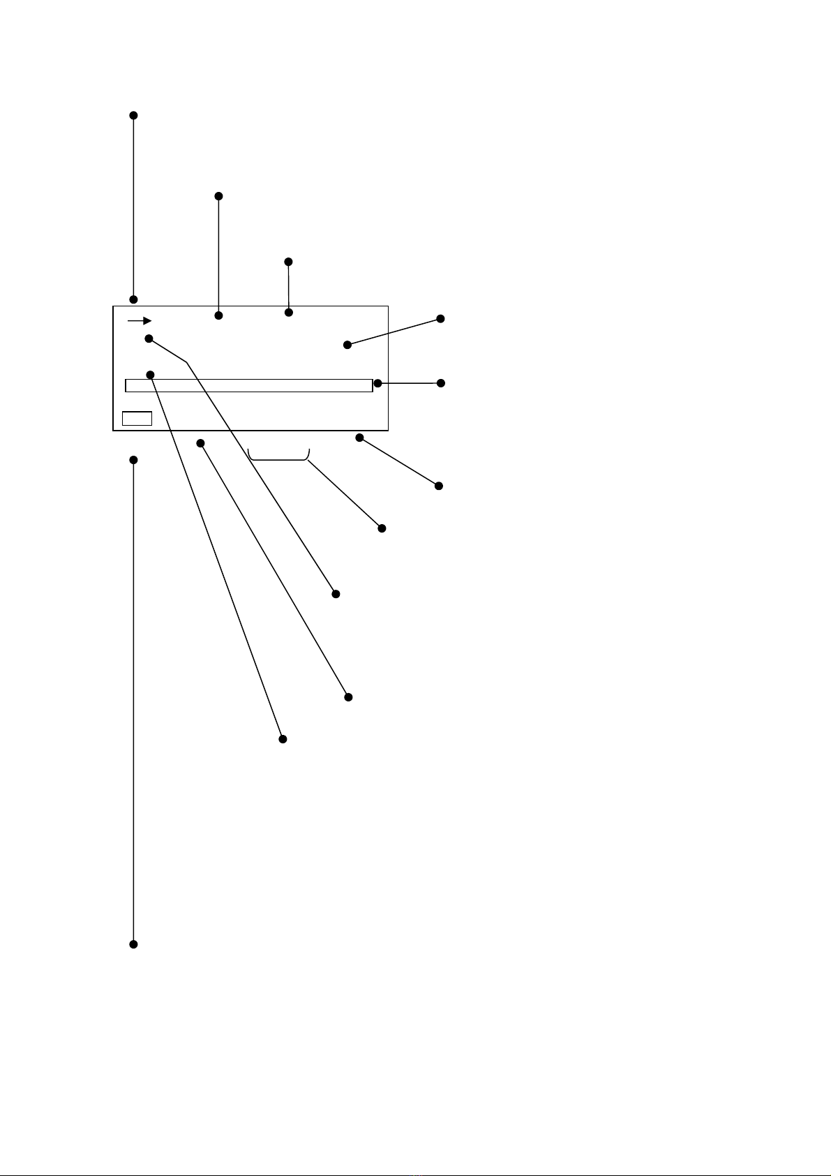
1. Names of each portion
Threa e retaining ring Female screw for tripo
Front panel
Displaying portion Battery cover
Acceleration pick-up Si e panel
TYPE7833 Female screw for tripo
Si e panel
Calibration potentiometer
AC OUT connector
DC OUT connector
POWER switch
AC power a aptor connector
External Input/Output connector

7
2. Battery installation
When LCD isplay tells low battery, install new batteries.
For long-term measurement, install new batteries in a vance.
The following isplays tell you the con ition of the batteries.
Full Low Replace batteries.
To install new batteries:
1)Turn off the POWER switch.
2)The sli e is one while pushing the battery li by the thumb.( Refer to the figure below)
3)Put the new batteries in the case, then shut the cover. The insi e of the case shows you the
irection of the batteries.
CAUTION
・ Do not put the batteries in the wrong irection.
・ These four batteries shoul be replace at the same time.
・Battery life is approximately:
20 hours (Alkaline batteries, continuous operation)
10 hours (Manganese batteries, continuous operation)
・Use of LCD back-light shortens the life of the batteries (approximately 1/3).
3. AC power a aptor
1)Turn off the POWER switch.
2)Connect the optional AC power a aptor to the AC power a aptor connector.
3)Put the AC plug in the AC 100V outlet.
Power consumption Approx. 2VA
CAUTION
・ The specification article of our company shoul be use for conversion
transformers, such as an AC/DC a aptor ,AC200V an etc. in the case of using
overseas, at any cost.
The failure by combination other than the specifie goo s cannot be guarantee .
AC power a aptor connector
“OPEN” pushing an sli e in
the irection of the arrow.

8
4. LCD A justment
You can a just LCD contrast, when the batteries were low, or when the new batteries were
installe .The proce ure is as follows.
Menu key
Cursor key
Set key
Screen switching key
1) When you press the Menu key, the following screen appears.
<menu> 1/2
Meas Mode : Manu
Interval : Single
I/O : O f f
OUT Ch : X
LCD cont : *****
date y/m/d : 00/01/01
time : 00:00:00
2) Select LCD cont with Cursor key , then move the cursor rightwar with key.
3) A just the LCD contrast with key, then press Set key to save the setting.
The greater the * mark increases, the thicker the contrast becomes.
After pressing Set key, the cursor moves to leftwar .
4) If you want to go back to measurement mo e, press View key.
CAUTION
There can be a temporary appearance of a line on the LCD
when the Power switch is turne OFF. It is a normal
phenomenon an not a problem or failure.

9
5. Calen ar A justment
To a just the calen ar (time), operate as follows.
You can a just calen ar in the Menu mo e in the same way as LCD a justment.
Menu key
1) When the menu key is inputte ,
the following menu screen appears.
<menu> 1/2
Cursor key Meas Mode : Manu
Set key Interval : Single
I/O : O f f
OUT Ch : X
View key LCD cont : ***** Date
date y/m/d : 00/01/01 a justment
time : 00:00:00
Time a justment
【Calen ar a justment】
1) Select ate y/m/ with Cursor key , then move the cursor rightwar with key.
2) Set the year/month/ ay with key, then press Set key to save the setting.
After pressing Set key, the cursor moves to leftwar .
3) If you want to go back to the measurement mo e, press View key.
【Time a justment】
1) Select time with Cursor key , then move the cursor rightwar with key.
2) Set the hour:minute:secon with key, then press Set key to save the setting.
After pressing Set key, the cursor moves leftwar .
3) If you want to go back to the measurement mo e, press View key.
【Caution】
Be sure to enter the ate ( ate y/m/ ) in the or er of “year → month → ay.”
Input any figure of; y(year): 00 – 99, m(month): 01 – 12, an ( ay): 01– 31.
Ex.) For November 30, 2003
Correct) 03/11/30
Incorrect) 11/30/03 30 has been entere for m(month). Input any figure of
01 through 12.
Be sure to enter the time in the or er of “hour → minute → secon .”
Input any figure of; h(hour): 00 – 24, m(minute): 00 – 59, s(secon ) 00 – 59.
Ex.) For 23:58:32
Correct) 23/58/32
Incorrect) 32/58/23 32 has been entere for h(hour). Input any figure of
00 through 24.
<Entry of incorrect ate an time>
The instrument has a function for outputting ata that was measure or is being measure
to a personal computer.
During recovery of ata, if an incorrect ate an time are entere , an error message “Econver
Error” is isplaye on the screen an ata recovery cannot be carrie out.

10
6. LCD back-light
In a case where the isplay part is har -to-rea in a ark place or at night, it can be rea by
lighting the backlight on the LCD.
Light key
1) When the light key is presse , the LED on the isplay part (LCD) lights.
2) The LED turns off by pressing the light key again.
Even when the LED stays lit, it automatically turns off in approx. 30 secon s.
3) As the batteries are consume , the backlight turns ark.
Caution
・ When the LED lights, batteries are consume in a shorter perio of time.

11
Section 2 Basic operations
1. Switching of isplay screens an names of each portion
1-1 Switching of isplay screen
The screen has three isplay mo e types of normal screen, 3ch screen an list screen, which
can be switche with the screen switching key.
The isplay on the screen is sequentially switche at each time when the screen switching key
is presse .
Besi es the above, the screen switching key is also use for returning from the menu isplay
screen escribe in Chapter 4.
Screen switching key
<Display of normal screen>
<Display of 3ch screen>
<Display of list screen>
1s 000h00m00s
X-110 Lv
100.0
dB
Y-110 Lv
100.0
dB
Z-110 Lv
100.0
dB
1s 000h00m00s
X
dB
100.0
50 110
X
-
110
Lv : 100.0
Lveq : 100.0
LMin : 100.0
LMax : 100.0
1s 000h00m00s
Lv05 : 100.0
Lv10 : 100.0
Lv50 : 100.0
Lv90 : 100.0
Lv95 : 100.0
Manu
Manu
L
v
Manu
12
1-2 Display of normal screen
→: Display of operating status
→: Start Stop key input switches to measuring status
■: Pause key input switches to temporary stop status
00s: Display of measuring time
Displays the time set with Meas Time key.
00h 00m 00s: Display of measuring elapse time
Counts the measuring time with Start Stop key input.
Displaye ata
Displays the present value by igital value.
Bar isplay
Displays the present momentary value with a
bar.
Range isplay
Displays the range set with the Range key.
Warning isplay
When the measure value is smaller than the range,
Un appears, an when it is greater than the range,
Ov appears.
ch isplay
Displays ata selecte with the X, Y, Z key.
X, Y, Z
Cal isplay
Calibration mo e is set by Cal key input.
Filter isplay
Displays frequency correction set with Lv, Lva key.
Lv: Vibration level
Lva: Vibration acceleration level (flat characteristics)
Measurement mo e isplay
Displays the mo e set with a combination of Lv, Lva key an Mo e
Leq・Lx key.
Lv Lva Lv eq Lvaeq Lv xx Lvaxx
Display of battery remaining
Displays the battery capacity remaining accor ing to four stages.
・ The isplaye ata isplays the ynamic characteristics an correcte frequency in intervals of
approx. 1 secon .
・ The bar isplays the value of the isplaye ata in intervals of approx. 0.1 secon s.
1s 000h00m00s
X
Lv dB
100.0
50 110
Cal Un Ov

13
1-3 3ch screen isplay
This mo e isplays only ata for 3ch simultaneously without a bar isplay.
This screen appears by inputting the View key on the normal screen isplay or list screen
isplay.
Vibration level (acceleration level), power level or hour rate vibration level, etc., can be selecte
with Mo e Leq・Lx key, an isplaye . Other content isplaye is the same as that on the
normal screen isplay.
Note) Range, X, Y an Z keys o not operate.
1-4 List screen
This mo e isplays all ata which are in measurement on one screen.
This screen appears by inputting the View key on the normal screen pieces of isplay or list
screen isplay.
Nine ata such as Vibration level (acceleration level), power level an hour rate vibration level
can be checke on a list. The channel to be isplaye can be selecte by inputting the X, Y an
Z key.
Other content isplaye is the same as that on the normal screen isplay.
Display of ata
Note) Range, Mo e Leq・Lx keys o not operate.
1s 000h00m00s
X
-110
L
v
100.0
dB
Y
-110
L
v
100.0
dB
Z
-110
L
v
100.0
dB
X
-
110
Lv : 100.0
Lveq : 100.0
LMin : 100.0
LMax : 100.0
1s 000h00m00s
Lv05 : 100.0
Lv10 : 100.0
Lv50 : 100.0
Lv90 : 100.0
Lv95 : 100.0
Manu dB
Manu

14
1-5 Operation of panel switch an list of functions
Cursor key
● Light: Backlight for LCD
For etails, refer to “Section 1-7. How to use LCD backlight.”
● Menu : Menu key
For etails, refer to “Section 4-1. Menu operations.”
● Set: Register key for Set menu key
● : Cursor key
Use to set menu item an change range.
● Cal: Calibration mo e key
For etails, refer to “Section 2-3. Calibration.”
● Meas. Time: Measuring time selection key
For etails, refer to “Section 3 Measuring operations.”
● Lv・Lva: Filter selection key
For etails, refer to “Section 3 Measuring operations.”
● X,Y,Z: Channel switching key
For etails, refer to “Section 3 Measuring operations.”
● Range: Range switching key
For etails, refer to “Section 3 Measuring operations.”
● Mode Leq・Lx: Measuring mo e switching key
For etails, refer to “Section 3 Measuring operations.”
● Pause: Temporary stop key
For etails, refer to “Section 3 Measuring operations.”
● View: Display switching key
For etails, refer to “Section 2-1. Switching of isplay screens an
names of each portion.”
● Start Stop : Measurement start an stop key
For etails, refer to “Section 3 Measuring operations.”

15
3. Calibration
Before starting calibration, it is recommen e that the Vibration Level Meter be perio ically
calibrate .For calibration, there are two types for using the internal oscillator of the Vibration
Level Meter, an to calibrate inclu ing pick-up by using an agitator.
3-1 Calibration by internal oscillator
The oscillator (31.5Hz, sinusoi al wave), which is incorporate in this Vibration Level Meter,
allows for calibration.
Cursor key
Calibration key
Range key
1) Turn ON the power switch.
2) Press the Cal key to switch into calibration status. The lights in the calibration screen.
3) Press the Range key, select 110 B or 90 B with the cursor key , an press the
Range key to register.
4) Turn the calibration volume on the si e panel so that the level isplay in icates 110.0 B at
the age of a 110 B range, 90.0 B at the age of a 90 B range.
5) Press the Cal key one more time to en the calibration.
< Calibration screen >
When the range key is presse ,
this flashes.
Calibration isplay
< Si e panel >
<Reference> The relationship between range isplay value an output voltage
Display value(B) Output voltage(V)
RANGE AC OUT DC OUT
50~110 30~90
110.0 90.0 0.316 2.500
3-2 Calibration with vibration calibrator TYPE 2110
Set the vibration level meter to the vertical (Z) an vibration level (Lv) measurement states.
Vertical (Z) vibration level (Lv) if the meter instruction value of the vibration level meter
is 97.2 B±1 B (96.2 B to 98.2 B) is a pass.
1s 000h00m00s
X
Lv
dB
110.0
50 110
Cal
Cal
Calibration volume

16
Section 3 Measuring operations
1. Measurement of vibration level (Lv)
Filter key
ch switching key
Range key
Measurement mo e key
Screen switching key
<Operations>
1) Switch the screen into the normal screen isplay with the View key.
2) Select the channel to be set with the X, Y, Z key.
3) Select the range in irection with the Range key an set with the Range key.
4) Set so that the measurement mo e isplay becomes Lv isplay with the Lv, Lva key an
Mo e Leq・Lx key.
5) Likewise, change the channel with the X, Y, Z key to set.
6) After setting, the vibration level in each channel can be measure with the X, Y, Z key.
7) When checking the three channels simultaneously, switch to 3ch screen isplay with the
View key.
<Display>
Channel to be set is change with the X, Y, Z key.
X → Y → Z
Digital isplay
Bar isplay
This flashes with the Range
key.
Select the range with the cursor
key , an set with the
Range key.
・ The igital isplay is up ate every one secon , an isplays the present vibration level.
・ The bar isplay is up ate every 0.1 secon s to be isplaye .
・ There is no particular nee to press the Start key.
1s 000h00m00s
X
Lv
dB
100.0
50 110
Manu

17
2. Measurement of vibration acceleration level (Lva)
This level is the vibration level when the frequency correction is Flat.
<Operation>
1) The operation is the same as that in the previous item of “Measurement of vibration level
(Lv).”
2) Set with the Lv, Lva key so that the vibration isplay mo e becomes Lva isplay.
<Display>
When Lv, Lva key is inputte , the isplay changes from Lv to Lva.
・ Other isplays an operations are the same as that in the “Measurement of vibration level
(Lv).”
1s 000h00m00s
X
L
Va
dB
100.0
50 110
Manu

18
3. Measurement of power average level (Lveq)
Filter key
ch switching key
Range key
Start Stop key
Measuring mo e key
Temporary stop key
<Operations>
Operations are the same as that in the “Measurement of vibration level (Lv).”
1) Select the channel to be set with the X, Y, Z key.
Select the range in which approx. 2/3 of the bar isplay is colore with the Range key an
cursor key , an set with the Range key.
Select the Lv with the Lv, Lva key, an set with the Mo e Leq・Lx key so that the
measurement mo e isplay becomes Lveq.
2) Start measurement with the Start・Stop key. When the Start・Stop key is inputte , the ata
at that time is calculate an isplaye . (When the Pause key is inputte , measurement is in
a temporary stop state, an when the Pause key is presse again, measurement starts)
<Display>
→: When the Start・Stop key is inputte , this is switche into the
measuring state. Lights
■: When the Pause key is inputte , this is switche into temporary stop
state. Lights
The isplaye ch changes with the X, Y, Z key.
X → Y → Z
The isplay changes with the Meas. Time key.
Bar isplay
1s 000h00m00s
L
V
eq dB
50 110
Manu
66.0
X

19
4. Measurement of hour rate vibration level (Lx)
<Operation>
Hour rate vibration level (Lx): Lvxx or Lvaxx (xx is 05, 10, 90 or 95)
1) Select the measuring item with the Mo e Leq・Lx key an Lv・Lva key.
2) Set the measuring time with the Meas. Time key.
3) Press the Start・Stop key to start measurement.
4) The measurement en s at the measuring time set with the Meas. Time key. Or, press the
Start・Stop key to en measurement.
<Display>
→:When the Start・Stop key is inputte , this switches into a measuring state.
■:When the Pause key is inputte , this is switche into temporary stop
state.
The isplaye ch changes with the X, Y, Z key.
X → Y → Z
Set the measuring time with the Meas. Time key.
→: Measuring state ■: The measuring time cannot be change
in a temporary stop state.
Setting can be change as shown in Section 4-3. Mo e Set screen
escription (2/2) page 23.The mo e set in the items for View is isplaye
on the normal screen.
・ When the View key is presse , a list can be isplaye on the list screen isplay.
When Lv key is set
When Lva key is set
Normal screen isplay ⇒
List screen isplay
Lvaeq ⇒ Laeq
Lva
05
⇒ La
05
Lva
10
⇒ La
10
Lva
50
⇒ La
50
Lva
90
⇒ La
90
Lva
95
⇒ La
95
Even when measuring vibration level an power average in the previous section, the
measurement starts automatically when the Start・Stop key is inputte .
X
-
110
Lv : 100.0
Lveq : 100.0
LMin : 100.0
LMax : 100.0
1s 000h00m00s
Lv05 : 100.0
Lv10 : 100.0
Lv50 : 100.0
Lv90 : 100.0
Lv95 : 100.0
Manu dB
1s 000h00m00s
Lv
05 dB
50 110
Manu
66.0
X
X
-
110
Lva : 100.0
Laeq : 100.0
LMin : 100.0
LMax : 100.0
1s 000h00m00s
La05 : 100.0
La10 : 100.0
La50 : 100.0
La90 :
100.0
Lav95 :
100.0
Manu dB
Table of contents
Other ACO Measuring Instrument manuals


