Acorn 80 User manual

Acorn 80
Installation Manual

2ACORN 80 Installation Manual
1 Introduction 3
1.1 Conventions 4
1.2 Safety 4
1.3 Installation Training 4
1.4 Transportation & Storage 4
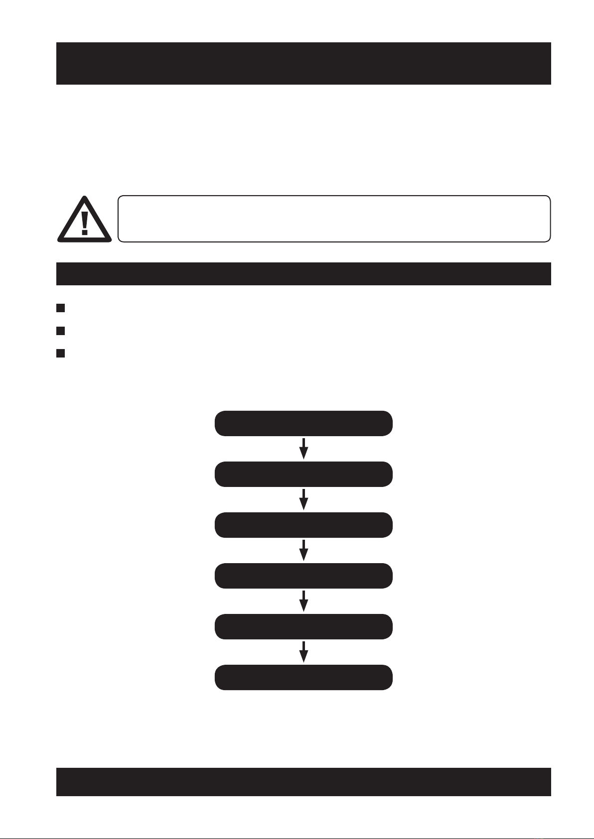
2 Installation Flow Chart 5
3 Rail Installation 6
4 Fitting Carriage to Rail 10
5 Rail Support Kit 12
5.1 Parts Included In The Rail Support Kit 12
5.2 Fitting Instructions 13
5.3 Wall Support Fixing Position Dimensions 15
6 Fitting Seat to Carriage 16
7 Fitting Rail Equipment 17
8 Programming 18
8.1 Programming Instructions 18
8.1.1 Pre-power Up Sequence 19
8.1.2 Power Up Sequence 19
8.1.3 Calibrating The Levelling 19
8.1.4 Programming The Top Terminal Limit 19
8.1.5 Programming The Rail 20
8.1.6 Bottom Parking 21
8.1.7 Intermediate/Park Charge Point 22
8.1.8 Intermediate/Landing Charge Point 22
8.1.9 Checking The Program 22
8.1.10 Amending The Program 23
8.1.11 Programming Do’s & Don’ts 23
9 OSG (Over-speed Governor) 24
9.1 Over-speed Governor (OSG) 24
9.1.1 Testing the OSG 24
9.1.2 Re-setting the OSG 24
10 Fitting Seat to Carriage 27
10.1 Testing Lift Operation 27
10.2 Final Checks 27
11 De-installation 28
Appendices 29
Appendix 1 - Installation Checklist 29
Appendix 2 - Recommended Tool List 30
Appendix 3 - Recommended Torque Settings 31
Appendix 4 - Recommended Lubricants 32
Appendix 5 - Wiring Diagrams - Charge System 33
Appendix 5 - Wiring Diagrams 34
Appendix 6 - Example Installation Drawing 35
Appendix 7 - Installation & Programming The Powered Hinge 36
Appendix 8 - Diagnostic Display 40
Appendix 9 - Remote Control Radio Channels 41
Appendix 10 - Rationalisation Procedures 42
10.1 Changing Hand Of Seat 42
10.2 Replacing Seat Spacer On-site 44
10.3 Assembly Of Powered Swivel On-site 47
10.4 Connecting Supercharger Link 52
10.5 Replacing Seat Adapter Plate On-site 54
10.6 Replacing Carriage Front Cover / Arm Harness 58
10.7 Replacing On / Off Switch With Blanking Plate 62
10.8 Replacing Back Cover On / Off Switch With Blanking Plate 66
10.9 Technical Drawings 69
10.9.1 530 Powered Swivel Seat Spacer Complete 69
10.9.2 550 Powered Swivel Seat Spacer Complete 70
10.9.3 580 Powered Swivel Seat Spacer Complete 71
10.9.4 530 Powered Swivel R/H Seat Spacer Complete 72
10.9.5 550 Powered Swivel R/H Seat Spacer Complete 73
10.9.6 580 Powered Swivel R/H Seat Spacer Complete 74
10.9.7 Carriage Front Cover Assembly 75
10.10 Seat Adaptor Plate Assembly Instructions 76
10.11 Seat Adaptor Plate Retro-fit Kit 78

3
ACORN 80 Installation Manual
INTRODUCTION
This manual contains installation (and de-installation)
instructions for the Acorn 80 Stairlift.
Other documents available include:
Survey Manual
Servicing & Maintenance Manual
User Manual
Product Price Guide
Parts Price Guide
SECTION 1
Introduction

4ACORN 80 Installation Manual
SECTION 1
Introduction
Throughout the manual comments may be inserted as follows:
1.1 Conventions
INFORMATION TO PREVENT A DANGER
TO YOURSELF OR OTHER PEOPLE AND/OR DAMAGE TO EQUIPMENT.
SUPPLEMENTARY INFORMATION.
1.2 Safety
Any national rules and regulations concerning safety, electrical work or environmental protection should
supplement, and may supersede, this document.
1.3 Installation Training
THIS STAIRLIFT MUST ONLY BE INSTALLED BY TRAINED PERSONNEL.
TRAINING CAN USUALLY BE ARRANGED FREE OF CHARGE VIA YOUR LOCAL AREA
REPRESENTATIVE OR THROUGH ACORN TECHNICAL SERVICES DEPARTMENT. A VIDEO
COMPACT DISK (VCD), SHOWING INSTALLATION PROCEDURES, IS ALSO AVAILABLE AS A
TRAINING AID FOR TRAINED PERSONNEL.
1.4 Transportation & Storage
THE CARRIAGE COMES READY FOR INSTALLATION ASSEMBLED ON A TRANSFER RAIL (T).
IT SHOULD ONLY BE REMOVED FROM THE RAIL WHEN IT IS TRANSFERRED ONTO THE
RAIL SYSTEM.
The lift system is supplied in 3 components
•RailsandFittings
•CarriageAssembly
•SeatAssembly
The carriage assembly and transfer rail weighs 43.4 Kilograms (96 Pounds).
During installation suitable safe lifting procedures to handle this weight must
be used. Whenever possible hold the transfer rail to pick up the carriage.
ON NO ACCOUNT MUST POWER TOOLS BE USED TO WIND THE CARRIAGE
ON OR OFF THE RAIL.

5
ACORN 80 Installation Manual
INSTALLATION FLOW CHART
ONLY ACORN TRAINED ENGINEERS SHOULD CARRY OUT STAIRLIFT INSTALLATIONS. ALL
STATUTORY RULES AND REGULATIONS CONCERNING SAFETY, ELECTRICAL WORK OR
ENVIRONMENTAL PROTECTION MUST BE OBSERVED.
1 Ensure that you have the correct installation drawing.
2Check all components received are correct and match the drawing and check sheets.
3Carefully remove the lift components from their packaging.
A suggested tool list is included in the Appendices.
RAIL INSTALLATION
FIT CARRIAGE TO RAIL
FIT SEAT TO CARRIAGE
FIT RAIL EQUIPMENT
PROGRAM THE LIFT
TESTING & COMPLETION
SECTION 2
Installation Flow Chart
Before Starting An Installation

Rail Sections (viewed from wall side of lift)
R Rail Section
TJ Top Joint Box
BJ Bottom Fixing Plate
P Pull Plate
C Countersink Screws
G Grub Screws
6 ACORN 80 Installation Manual
RAIL INSTALLATION
SECTION 3
Rail Installation
Tighten the rail fixings to the recommended Torque settings - see Appendix 2.
Joining the rail
The stairlift rail is shipped in several pieces. Refer to the installation drawing that all pieces are correct and
marked as per drawing. Check correct number of legs are supplied.
IF THE CARPET ON THE STAIRTREAD IS NOT FULL WIDTH, THEN MAKE THE CUSTOMER
AWARE THAT THE FOOT OF THE LEG WILL BE PUSHED UNDER THE CARPET. IT IS THE
CUSTOMERS RESPONSIBILITY TO HAVE A CARPET FITTER CUT THE CARPET TO FIT, OR FIT
AN INLAID PIECE. WE DO NOT CUT CARPET.
MAXIMUM LENGTH OF RAIL.
DO NOT EXCEED 25M, THIS IS THE LONGEST RAIL RECOMMENDED.

7
ACORN 80 Installation Manual
SECTION 3
Rail Installation
1Fit the legs (L) to the first sloping section of rail (R) or to the hinged section if fitted, as indicated on the
installation drawing. Insert the screw (S) through the leg clamp (C) and the hole in the top of the leg. Fasten
together with a nut on the screw.
2 Check the angle (A) of the first rail section with the installation drawing. Ensure face of rail is 90˚. If
necessary the legs can be adjusted for height, by screwing the leg up or down in the leg tube, to obtain the
correct angle. See sample drawing.
WHEN INSTALLING, INTERNAL OR EXTERNAL, 90˚ OR 180˚ WRAP ROUND SYSTEMS, IT IS
IMPORTANT TO ENSURE THAT ALL THE RAIL ANGLES AND SECTIONS ARE CORRECT.

8 ACORN 80 Installation Manual
SECTION 3
Rail Installation
3 Remove screws from protruding sections of top joints.
4Push the rail sections together.
ENSURE THAT THERE IS AT LEAST 180MM CLEARANCE BETWEEN THE WALL STRINGERS (S)
AND THE FRONT OF THE RAILS (R) OR ANY OBSTRUCTION.

9
ACORN 80 Installation Manual
SECTION 3
Rail Installation
5Fit the top box countersink screw (C) and grub screw (G).
6Pull the rail sections together by tightening up both countersink screws (C1).
7Expand the top joint box inside the rail sections by tightening up both grub screws (G) – this will give the
joint rigidity.
8Tighten all four countersink screws (C2).
9Check the rail joints are aligned with no gaps. Some small adjustment may be possible by loosening the
joint box and bottom fixing plate and re-aligning the rail sections.
10 Progressively fit the remaining rail sections, check horizontal sections are level and sloping sections are set
at the correct angle as shown on the installation drawing. (The final rail section may have to be fitted after
the carriage has been put onto the rail.)
11 Once the measurements and angles have been checked, secure the feet of the legs to the floor. Re-check
angles etc and adjust as necessary.
12 Lubricate the rack throughout using Interflon Fin Grease (902231) or equivalent.
HORIZONTAL SECTIONS MUST NEVER BE LESS THAN LEVEL. NO NEGATIVE DECLINE.
1
2
Note: If rail support kit needed see Section 5 (page 12).

10 ACORN 80 Installation Manual
SECTION 4
Fitting Carriage to Rail
THE CARRIAGE ASSEMBLY AND TRANSFER RAIL WEIGH 43.4 KILOGRAMS (96 POUNDS).
THE INSTALLATION ENGINEER MUST USE SUITABLE SAFE LIFTING PROCEDURES TO
HANDLE THIS WEIGHT.
Whenever possible hold the racked transfer rail (T) to pick up the carriage.
The carriage weight MUST BE SUPPORTED when transferring it onto the
sloping section of rail.
1 Fit the transfer rail (T) and carriage over the joint box. The carriage
may be transferred onto a horizontal section of rail or a sloping
section as shown here. Fit one screw to pull plate.
FITTING CARRIAGE TO RAIL
ENSURE THAT OSG HAS NOT BEEN ACTIVATED DURING TRANSIT. RESET IF NECESSARY
FOLLOWING PROCEDURES IN SECTION 8.
YOU MAY NEED TO REMOVE RAIL SECTIONS TO
ACHIEVE A 90° CUT FACE FOR T
TRANSFER RAIL TO MEET.

11
ACORN 80 Installation Manual
SECTION 4
Fitting Carriage to Rail
3 Level the carriage as required, using the winding handle (W) on the
levelling motor.
4 Check the carriage is level with a spirit level on the footrest.
2 Fit the winding handle (W) onto the top of the drive motor. Handwind
the carriage off the transfer rail (T) onto the fitted rail. Remove transfer
rail. Where necessary, fit the last section of rail.

12 ACORN 80 Installation Manual
SECTION 5
Rail Support Kit
In order to improve the stability of the Acorn 80 rail, a top bracket has been designed to secure the rail to the
wall. The inclusion of this part will be determined by the Drawing Office as part of the feasibility, but can also be
purchased when circumstances of the end user changes.
The part should be used in configurations where :
1 An angled cut is requested at the top of the rail.
2 The last leg at the top of the rail is over 40cm from the end of the rail.
The wall support bracket can be ordered as a spare part on part number SP1241648.
RAIL SUPPORT KIT
5.1 Parts Included In The Rail Support Kit
1x Wall support bracket
2x M12 Nyloc nuts
2x M12 Slim nuts
3x M12 washers
1x M12 studding

13
ACORN 80 Installation Manual
SECTION 5
Rail Support Kit
Drill a pilot hole in the rear of the top box section of
rail using a 5mm drill bit.
The hole must be as close to the top of the rail as
possible so as not to interfere with the travel of the
stairlift, but should not prevent fitting of the rail end
cap.
Drill the hole out to 13mm diameter to allow the
threaded studding to pass through.
Place one washer and M12 slim nut on one end of
the M12 studding and screw the studding into the
wall plate as shown.
5.2 Fitting Instructions

14 ACORN 80 Installation Manual
SECTION 5
Rail Support Kit
Cut the M12 studding to the correct length to fit
from the wall to the inside of the Acorn 80 rail
section, allowing enough length to fit a M12 nyloc
nut on the inside of the rail section. Fit a M12 slim
plain nut and plain washer as shown.
This length will vary depending on rail position and
depth of stringer etc. therefore must be measured
for each individual installation.
The rail support is fitted to the rail by inserting the
M12 threaded studding through the hole previously
drilled in the rail section, then fit a M12 plain washer
and M12 Nyloc nut to the end of the studding.
With the rail in position on the stairs, align the wall
fixing plate on the wall and mark the position of the
fixing holes.

15
ACORN 80 Installation Manual
SECTION 5
Rail Support Kit
Using suitable fixings for the type of wall
construction, fix the wall plate in place.
Once the wall plate has been secured and the rail
support legs have been fixed in place, the nuts for
the wall support bracket can be tightened.
Take care when tightening the wall support nuts
not to pull the rail out of line and therefore too
close to the wall.
5.3 Wall Support Fixing Position Dimensions

16 ACORN 80 Installation Manual
SECTION 6
Fitting Seat to Carriage
FITTING SEAT TO CARRIAGE
1 Apply the recommended grease to the swivel pin – see Appendix 3.
Ensure grub screw (G) is tight and the seat pin is secure.
2Place the thrust washer (T) over the swivel pin.
(Only applies to power swivel).
3Position the seat square with the main frame and locate
the swivel pin into its bearing bush, ensuring the thrust
washer is located, where applicable.
4Hold paddle arms down and push the seat fully down into the frame (F).
5Check the seat swivel locking mechanism operates correctly,
using the swivel paddles (SP).
6Connect the seat wiring (W) to the PCB connector.

17
ACORN 80 Installation Manual
SECTION 7
Fitting Rail Equipment
1 If necessary move the lift back along the rail using the winding handle.
2Fit the top & bottom charge points to the rail as shown on the installation drawing. Connect the charge
points to the battery charger.
3Test all charge points with a voltmeter (32v DC).
4Fit the top & bottom limit switch striker plates onto the back of the charge points.
5Fit the top & bottom mechanical stops to the rail rack.
6Fit the end cap to the final section of rail.
FITTING RAIL EQUIPMENT
THE NEXT STEP IS AN IMPORTANT SAFETY REQUIREMENT.

18 ACORN 80 Installation Manual
SECTION 8
Programming
PROGRAMMING
8.1 Programming Instructions
This procedure describes how to completely program the Stairlift. If the batteries are disconnected at any time
the program will be retained, except for the Datum Position and Top Terminal limit, which then must be
re-programmed in.
The lift orientation is set Left Hand or Right Hand for the program. Factory set.
A datum position is set at the top of the rail as the lift leaves the top charge point.
The top charge point position is set (Terminal Limit).
Carriage speeds are programmed in as the lift moves down the rail.
The bottom charge point position is set (Terminal Limit).
Programming is then completed for both up and down travel.
Three carriage speeds are possible:
CREEP SPEED (slow) is the default setting and is used just before stopping.
BEND SPEED when moving around vertical, inside horizontal bends and helical bends. It is also used as an
intermediate speed.
FULL SPEED along straight rail sections.
The following instructions should assist the installer if a ‘b’ fault is
present at install.
1Switch off the lift at the on/off switch.
2 Put a call in using rocker in switch in required direction.
3Switch the on lift with the on/off switch whilst holding the call in on the rocker switch.
4The lift will now drive.

19
ACORN 80 Installation Manual
SECTION 8
Programming
8.1.1 Pre-power Up Checks
8.1.2 Power Up Sequence
8.1.3 Calibrating The Levelling
Remove the front cover and check that all
programming switches are in the off position, to the
left. Select LEFT or RIGHT hand install. Check that
the correct hand has been selected, as these switches
should not be changed at all from now.
Check that the seat holding switch is switched off. Connect the positive leads from both batteries to the
positive spade connectors on the board. The board will display the bottom right hand corner decimal point.
Switch on the seat holding switch. The selected hand of the lift will be displayed momentarily, then the
no datum set symbol will be displayed. The lift cannot be moved with this displayed.
ONLY TO BE DONE IF THE PCB HAS BEEN CHANGED. Now switch the PROGRAM MODE to ON.
Datum search will be displayed. Call the lift with either the rocker switch or the remote in either
direction. Using a spirit level on the footrest, finely adjust the potentiometer until the lift is level. Once
the level position is set, the potentiometer should not be altered after programming or the whole rail
MUST be programmed again.
8.1.4 Programming The Top Terminal Limit
Call the lift down off the charge point. As the positive charge plunger leaves the charge point, the
programming rail symbol will be displayed. This sets the “datum point”.
This is a reference point for the memory during programming of the rail. Stop the lift and drive
it back up onto the final limit striker. will be displayed. Note that the top terminal limit will be
approximately 10-15mm down from the final limit stop position. Adjust the striker to the required
position. This position depends on the angle of the rail at this point. When the correct position is
found, call the lift down the rail off the charge point, and then back up onto the final limit for a
second time. The carriage is now ready for programming down the full length of the rail.

20 ACORN 80 Installation Manual
SECTION 8
Programming
8.1.5 Programming The Rail
1Start with the lift parked at the top of the stairs and start in CREEP SPEED (C).
2Move the lift 50mm in the down direction then switch BEND SPEED to ON (B).
3Move the lift in the down direction a further 180mm then switch FULL SPEED to ON (F) (if applicable).
4On vertical bends when the portcullis is 100mm past the first joint line switch BEND SPEED to ON.
5On vertical bends when the portcullis is 440mm past the second joint line switch FULL SPEED to ON.
6On all bends (except external horizontal bends) when the portcullis (P) is above the first bend joint line
switch FULL SPEED to OFF - this reverts the lift to BEND SPEED (B) (if applicable).
7Repeat this procedure for all vertical, inside horizontal and helical bends on the installation.
USE THE PORTCULLIS AS A REFERENCE POINT WHEN MEASURING
ON SOME SHORT SECTIONS OF RAIL IT MAY NOT BE PRACTICAL TO APPLY FULL SPEED
BEFORE A BEND IS REACHED, IN THIS CASE LEAVE IN BEND SPEED AND MOVE LIFT IN
DOWNWARD DIRECTION.
Other manuals for 80
1
Table of contents
Other Acorn Stairlift manuals
Popular Stairlift manuals by other brands

Harmar Mobility
Harmar Mobility Vantage SL400 Installation and service manual

TKE
TKE S100 user manual

Powermate
Powermate L1 series Repair manual

Harmar Mobility
Harmar Mobility Pinnacle SL300 owner's manual

Lippe Lift
Lippe Lift T80 operating instructions

Lancaster
Lancaster Bruno Elan SRE-3000 Basic Troubleshooting