ACROME BALL AND BEAM User manual

2
©2015 Acrome Inc., All rights reserved.
Acrome Inc.
ITU ARI4 Science Park
Maslak, Istanbul
Turkey
Phone: +90 532 132 17 22
Fax: +90 212 285 25 94
Printed in Maslak, Istanbul
For more information on the solutions Acrome Inc. offers, please visit the web site at:
http://www.acrome.net
This document and the software described in it are provided subject to a license agreement.
Neither the software nor this document may be used or copied except as specified under the
terms of that license agreement. All rights are reserved and no part may be reproduced, stored
in a retrieval system or transmitted in any form or by any means, electronic, mechanical,
photocopying, recording, or otherwise, without the prior written permission of Acrome Inc.

3
Contents
1 OVERVIEW..................................................................................................................................... 4
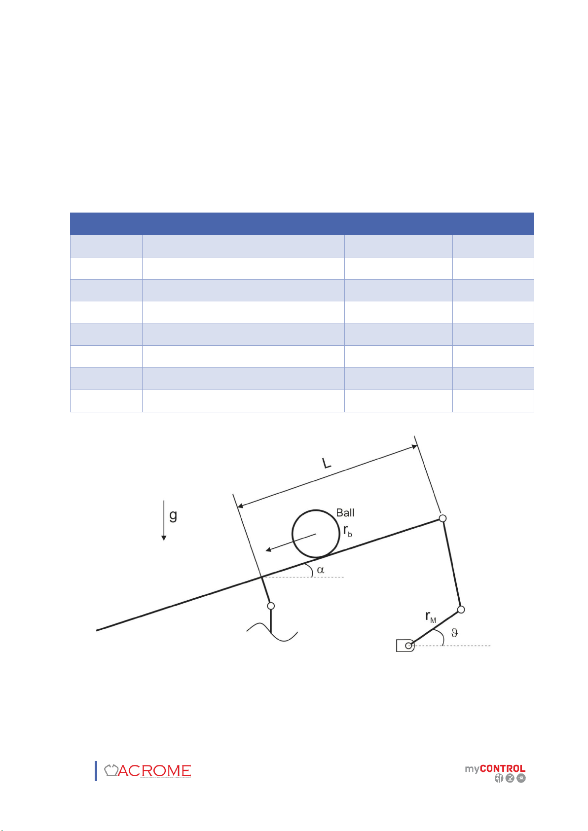
1.1 System Description................................................................................................................. 4
2 COMPONENTS............................................................................................................................... 5
2.1 RC Servo Motor (# 1).............................................................................................................. 6
2.2 NI myRIO (# 3) ........................................................................................................................ 6
2.3 ACROME Power Distribution Box (# 4).................................................................................. 7
3 TECHNICAL SPECIFICATIONS......................................................................................................... 8
4 WIRING.......................................................................................................................................... 9
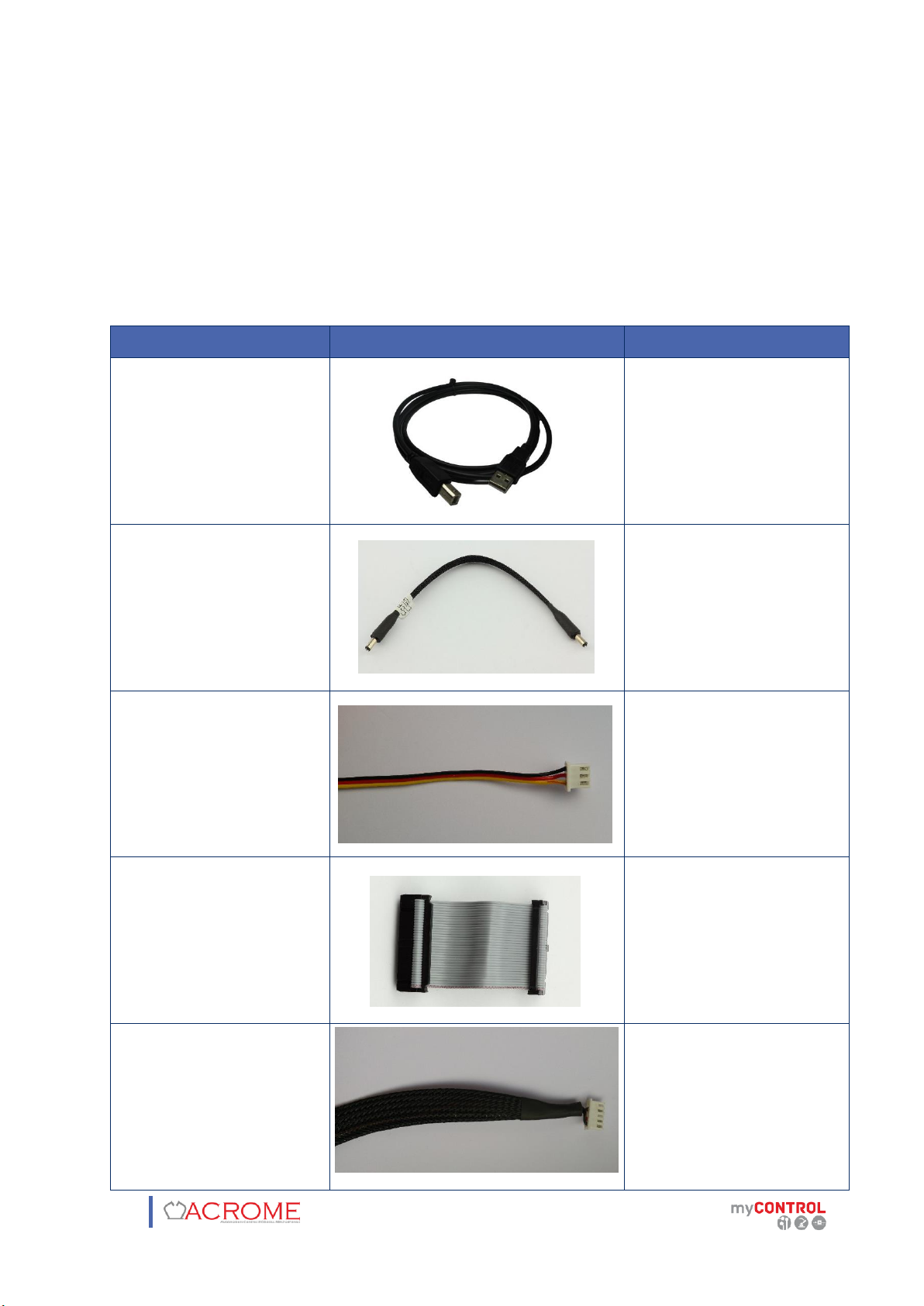
4.1 Cable Names........................................................................................................................... 9
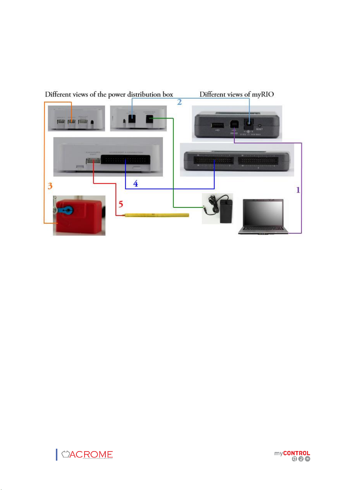
4.2 Connections.......................................................................................................................... 10
5 SETTING UP THE SYSTEM............................................................................................................ 11
5.1 MyRIO Preparation on NI MAX ............................................................................................ 11
5.1.1 Firmware Update .................................................................................................... 11
5.1.2 Software Update ..................................................................................................... 13
5.2 Installing Software Program via VI Package Manager (VIPM)............................................. 17
5.3 Getting Started..................................................................................................................... 20
5.4 Calibration............................................................................................................................ 21
6 TROUBLESHOOTING.................................................................................................................... 29
6.1 Connection Open FPGA VI Reference.................................................................................. 29

4
1 OVERVIEW
1.1 System Description
Ball and beam system consists of a beam on which a ball can be placed and free to move can
be seen in the Figure 1.1. Beam is connected to the base plate of the system over a cardan joint
with one degree of freedom. The Servo motor is connected to the beam over link with a rod
and ball joint. Potentiometer sensor sticks on the beam to measure the position of the ball.
Figure 1.1: ACROME Ball and Beam System
By controlling the servomotor, the angle of the beam can be adjusted to regulate the position
of the ball on the beam.

5
2 COMPONENTS
All the main components “ACROME Ball and Beam” are numbered and can be seen in the Figure
2.1. The numbers and the names of elements are listed in the Table 2.1 below.
Table 2.1: Descriptions and numbers of components
Numbers
Description
1
RC Servo Motor
2
Potentiometer Sensor
3
myRIO
4
ACROME Power Distribution Box
5
Mechanics of Beam
6
Adapter
Figure 2.1: Components of Ball and Beam System

6
Figure 2.2: The Potentiometer
2.1 RC Servo Motor (# 1)
RC servos are electromechanical devices that convert electrical signals to movement. They
provide simple and handy solutions to most control and robotic applications.
Figure 2.3: RC Servo Motor
2.2 NI myRIO (# 3)
myRIO has many ports and sensors on board including; analog inputs (AI), analog outputs (AO),
digital inputs and outputs (DIO), audio and power outputs, an accelerometer and LED’s. Also,
myRIO has a full size USB port that can be utilized as host and 802.11.bgn wireless module.

7
Figure 2.4: NI myRIO
2.3 ACROME Power Distribution Box (# 4)
The RC servo motor, sensor (potentiometer) and myRIO connections are located on ACROME
power distribution box which is shown in Figure 2.5. It also has a RGB led and switch mode
regulators.
Figure 2.5: ACROME Power Distribution Box

8
3 TECHNICAL SPECIFICATIONS
The Ball and Beam System has dimensions and parameters that are shown with α 𝑔, 𝐽𝑏below.
These dimensions and parameters of the system will be used in the mathematical model.
Table 3.1: Dimensions and parameters of the system
Symbols
Definition
Value
Unit
𝑳
Beam Length
0.5
[m]
𝒓𝑴
Motor Arm Length
0.0245
[m]
𝒓𝒃
Radius of the Ball
0.0175
[m]
𝒎𝒃
Mass of the Ball
0.175
[kg]
𝑱𝒃
Rotational Inertia of the Ball
0.00002143
[kg ∗ m2]
𝒈
Acceleration due to Gravity
9.81
[m/s2]
𝜶
Beam Angle
(Variable)
[degrees]
Motor Angle
(Variable)
[degrees]
Figure 3.1: Free Body Diagram of Ball and Beam System

9
4 WIRING
4.1 Cable Names
Cables which are used in the ball and beam system are defined and denominated as seen in
Table 4.1 below.
Table 4.1: Cable Descriptions
Cable Names
View of the Cables
Definitions
1. Usb Cable
This cable provides the
connection between PC and
myRİO
2. myRIO Power Cable
Output power of the
distribution box is
connected to myRIO with
this cable in order to
provide power.
3. RC Servo Motor Cable
This cable connects RC
servo motor to power
distribution box to
transmits PWM waves.
4. Digital I/O Cable
This cable transmits signals
between myRIO and power
distribution box.
5. Potentiometer Cable
This cable connects
potentiometer to power
distribution box in order to
transmit the position data
of the ball to myRIO.

10
4.2 Connections
In order to use the system, all cables mentioned above should be connected properly. All the
essential connections among the components are shown in Figure 4.1.
Figure 4.1: Ball and Beam System Connections

11
5 SETTING UP THE SYSTEM
5.1 MyRIO Preparation on NI MAX
NI MyRIO microprocessor has a RT LabVIEW software inside. To connect microprocessor
domain to Computer one, both microcontroller and computer has to install the same LabVIEW
version. Please notice that latest versions may need latest firmware. This chapter shows how
to update software and firmware versions on NI Measurement and Automation Explorer (NI
MAX) program.
Figure 5.1: "NI MAX" Shortcut Logo
5.1.1 Firmware Update
Before we started, please be sure that NI MyRIO is powered on and connected to your
computer with your USB Cable.
1) Browse your NI MAX program to open.
2) From the left column of the window, please expand “Remote Systems” Tab by clicking
on the “>” arrow
3) Find your MyRIO product name with a tiny MyRIO icon on the left.
4) Click on your MyRIO product name to see “System Settings” page on the right. (see
Figure 5.2)

12
Figure 5.2: "NI MAX" Remote Control Screen
5) Click on “Update Firmware” button
6) Select the latest version of firmware from the pop-up window. (See Figure 5.3)
Figure 5.3: Firmware Versions Pop-Up Window

13
7) Please wait until “The firmware update completed successfully” message comes out.
(See Figure 5.4)
Figure 5.4: Successfully Firmware Update Message
5.1.2 Software Update
Before we started, please be sure that NI MyRIO is powered on and connected to your
computer with your USB Cable.
1) Browse your NI MAX program to open.
2) From the left column of the window, please expand “Remote Systems” Tab by clicking
on the “>” arrow
3) Find your MyRIO product name with a tiny MyRIO icon on the left.
4) From the left column of the window, please expand “MyRIO-Your_Product_Name” Tab
by clicking on the “>” arrow
5) Right click on the “Software” section
6) Click on “Add/Remove Software” (See Figure 5.5)
7) When Login window pops-up, insert “admin” to username and remain empty to the
password. Press enter. (See Figure 5.6)

14
Figure 5.5: Accessing Add Remove Software
Figure 5.6: Login Window
8) Installation window may take some time before it opens.
9) After window pops-up, available versions of LabVIEW software will be shown on the
left. Please select the LabVIEW version you use on your computer
10) Click “Next >>” button. (See Figure 5.7)

15
Figure 5.7: Version Selection
11) Select the add-ons you want to install in NI MyRIO. Then click “Next >>” (See Figure 5.8)
Figure 5.8: Add-On Selection

16
12) Apply one last window then installation starts.
13) Wait until software successfully updated message shows up. (see Figure 5.9)
14) Click “Finish” to complete the software update.
Figure 5.9: Successfully Software Update Message

17
5.2 Installing Software Program via VI Package Manager (VIPM)
To download the latest version of Acrome Ball and Beam software, please download VI Package
Manager Program. You can find download link below.
Download Link : https://vipm.jki.net/download
Figure 5.10: vipm.jki.net Download Link for VI Package Manager
When you successfully download and install the program, please browser “VI Package
Manager” to open.
Figure 5.11: VI Package Manager Shortcut Icon
After program opens, (It takes some time to download all the available packages) please search
for “Ball and Beam Software” then double-click on it. From the window that pops up, please
select your LabVIEW version then click “Install” button. Accept the license agreements and wait
until installation completes.

18
Figure 5.12: Ball and Beam Software Download Page on VIPM
Figure 5.13: Ball and Beam Software License Agreement

19
After “Ball and Beam Software” has been installed completely, “Show Examples” button will be
available on the page shown in Figure 5.12. Please press the button then click on “Ball and
Beam Project.lvproj” from the opened file window. The software project will be opened by
LabVIEW. From the Project Explorer, please click on “Help”. Find and click “Activate Add-ons”.
Figure 5.14: Activate Add-ons in LabVIEW Project Explorer
From “Third-Party Add-on Activation Wizard” window, please select “Ball and Beam Software”
and click “Activate >>” button. Insert your License ID and Password and now your LabVIEW
software will be activated.
Figure 5.15: Third Party Add-on Activation Wizard Window

20
5.3 Getting Started
After the connections are carefully realized, copy "Ball and Beam Project" folder located under
ACROME BB CD-ROM under C:\. And open the "Ball and Beam Project" in LabVIEW.
Required LabVIEW Software Modules :
-FPGA Module
-Real Time Module
-Control Design and Simulation Module
-MyRIO Toolkit
Figure 5.16: "Ball and Beam Project" Window
1. After wiring and the connection process, connect myRIO to a USB port of your computer.
2. Power up myRIO.
3. Connect to myRIO over "Ball and Beam Project".
Table of contents
Other ACROME Educational Equipment manuals
Popular Educational Equipment manuals by other brands

Quanser
Quanser QNET Physics and Dynamics quick start guide

Enabling Devices
Enabling Devices Spinning Light Show user guide

Rompa
Rompa 19029 manual

Bresser
Bresser NATIONAL GEOGRAPHIC LAND AND WATER EXPLORATION... operating instructions

Simulaids
Simulaids RANDY 9000 Instruction and Care Manual

HeartSine
HeartSine samaritan SAM 450P user manual