Acrosser Technology AND-J190N2-C612 User manual

AND-J190N2-C612, AND-J180N2-C612 User Manual
User Manual
Acrosser Technology Co., Ltd.
www.acrosser.com
AND-J190N2-C612
AND-J180N2-C612
A Bay Trail Networking Microbox
Powered by Intel®Celeron®
J1900/J1800 with 6x GbE LAN,
and 2-pair Bypass LAN

AND-J190N2-C612, AND-J180N2-C612 User Manual
2
Acrosser Technology Co., Ltd.
Disclaimer
For the purpose of improving reliability, design and function, the information in this document
is subject to change without prior notice and does not represent a commitment on the part of
Acrosser Technology Co., Ltd.
In no event will Acrosser Technology Co., Ltd. be liable for direct, indirect, special, incidental, or
consequential damages arising out of the use or inability to use the product or documentation,
even if advised of the possibility of such damages.
Copyright
This document contains proprietary information protected by copyright. All rights are reserved.
No part of this manual may be reproduced by any mechanical, electronic, or other means in
any form without prior written permission of Acrosser Technology Co., Ltd.
Trademarks
The product names appear in this manual are for identication purpose only. The trademarks
and product names or brand names appear in this manual are the property of their respective
owners.
Purpose
This document is intended to provide the information about the features and use of the product.
Audience
The intended audiences are technical personnel, not for general audiences.
To read this User Manual on your smart phone, you will have to install an
APP that can read PDF le format rst. Please nd the APP you prefer from
the APP Market.
Ver: 100-001
Date: Aug. 26, 2016

AND-J190N2-C612, AND-J180N2-C612 User Manual
3
www.acrosser.com
Table of Contents
1. Introduction ...................................................................5
1.1. Specications ............................................................................................................ 5
1.2. Packing List ............................................................................................................... 6
1.3. System Dissection..................................................................................................... 7
1.3.1. Dimension.................................................................................................... 7
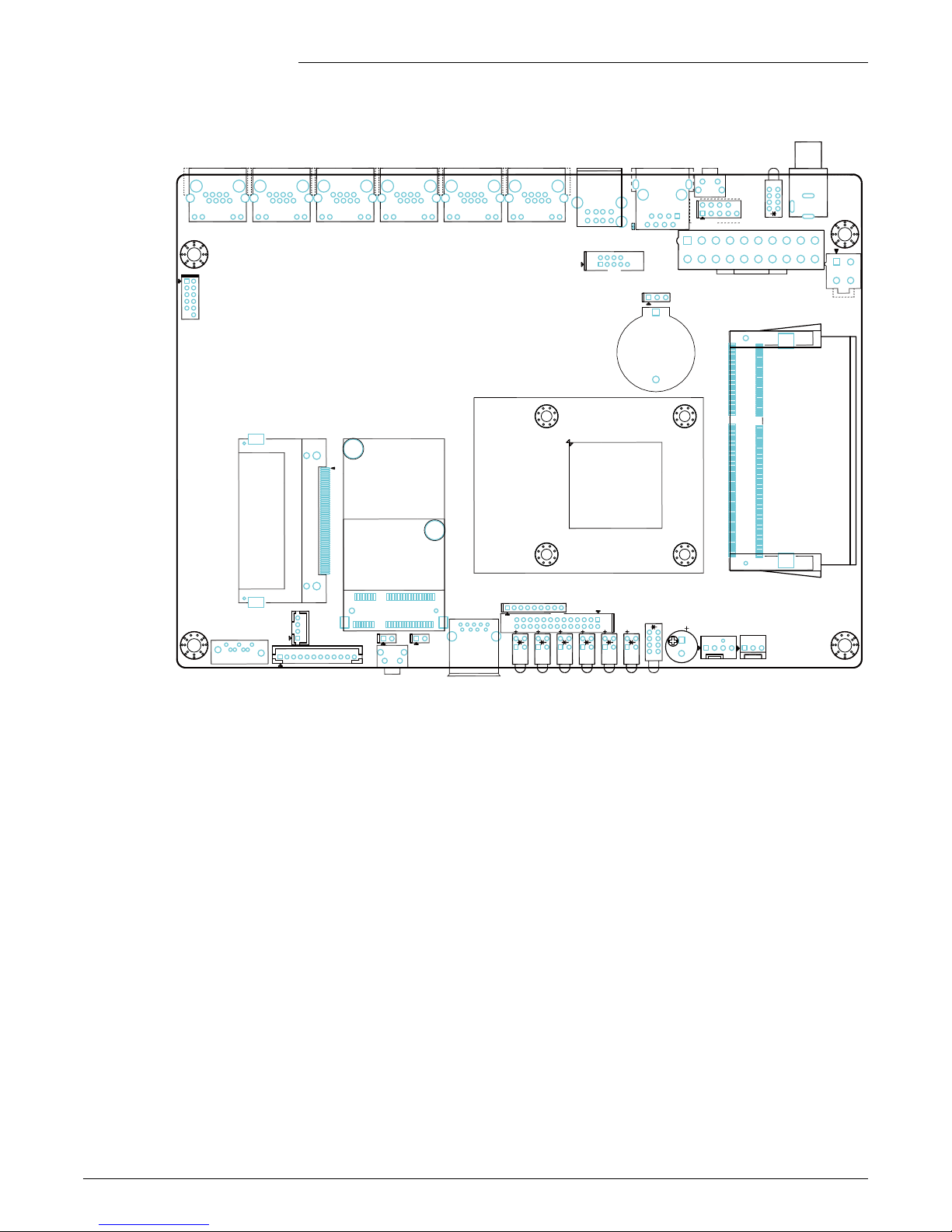
1.3.2. Board Layout ............................................................................................... 8
1.3.3. Jumper Settings........................................................................................... 9
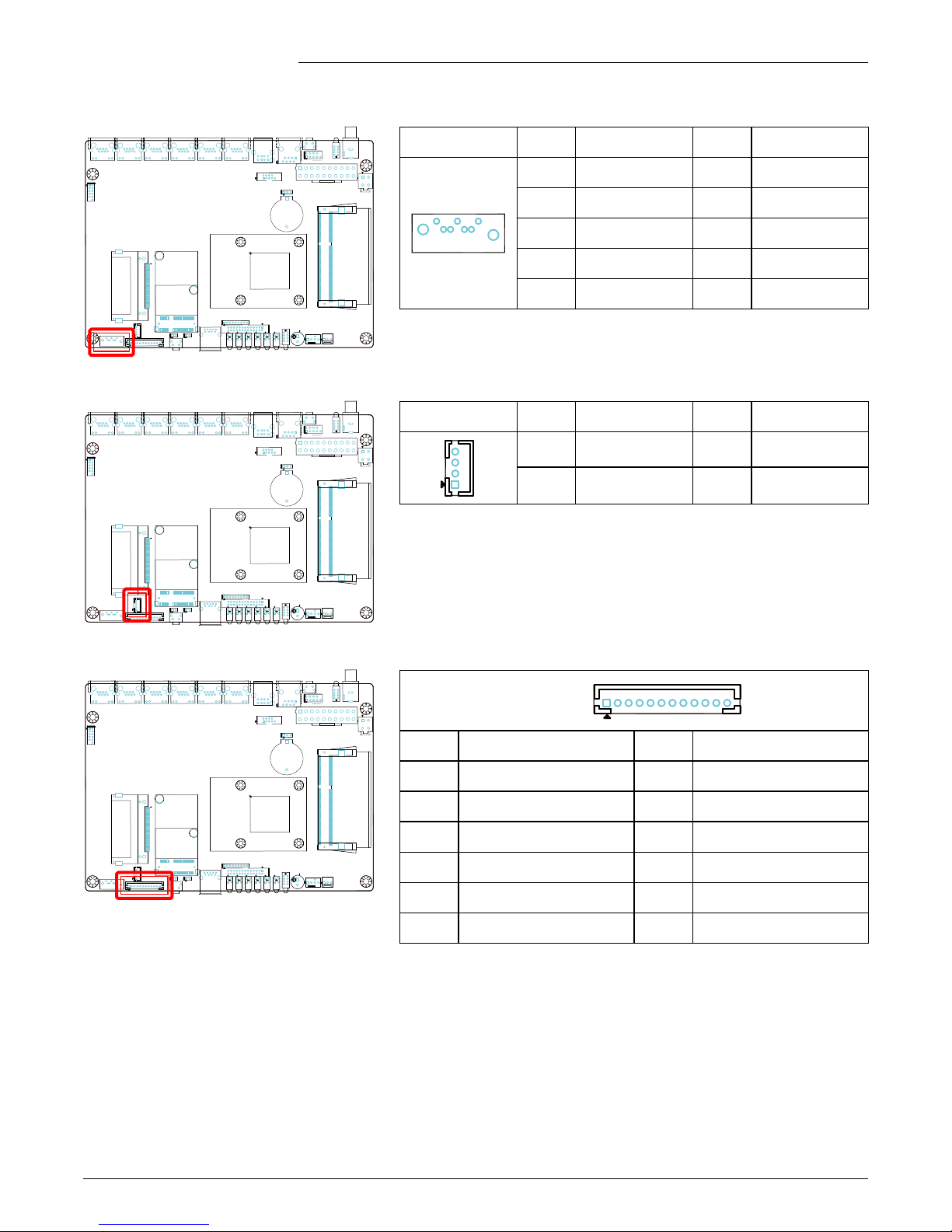
1.3.4. Onboard Headers/Connectors Pin Denition............................................... 9
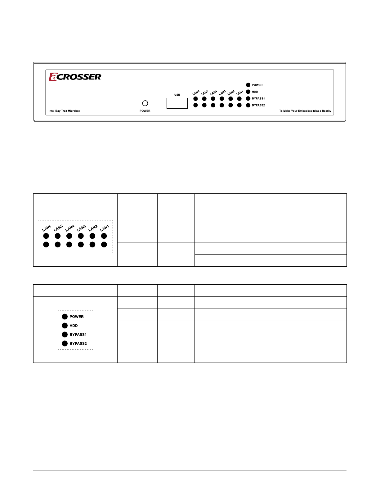
1.3.5. Front I/O..................................................................................................... 14
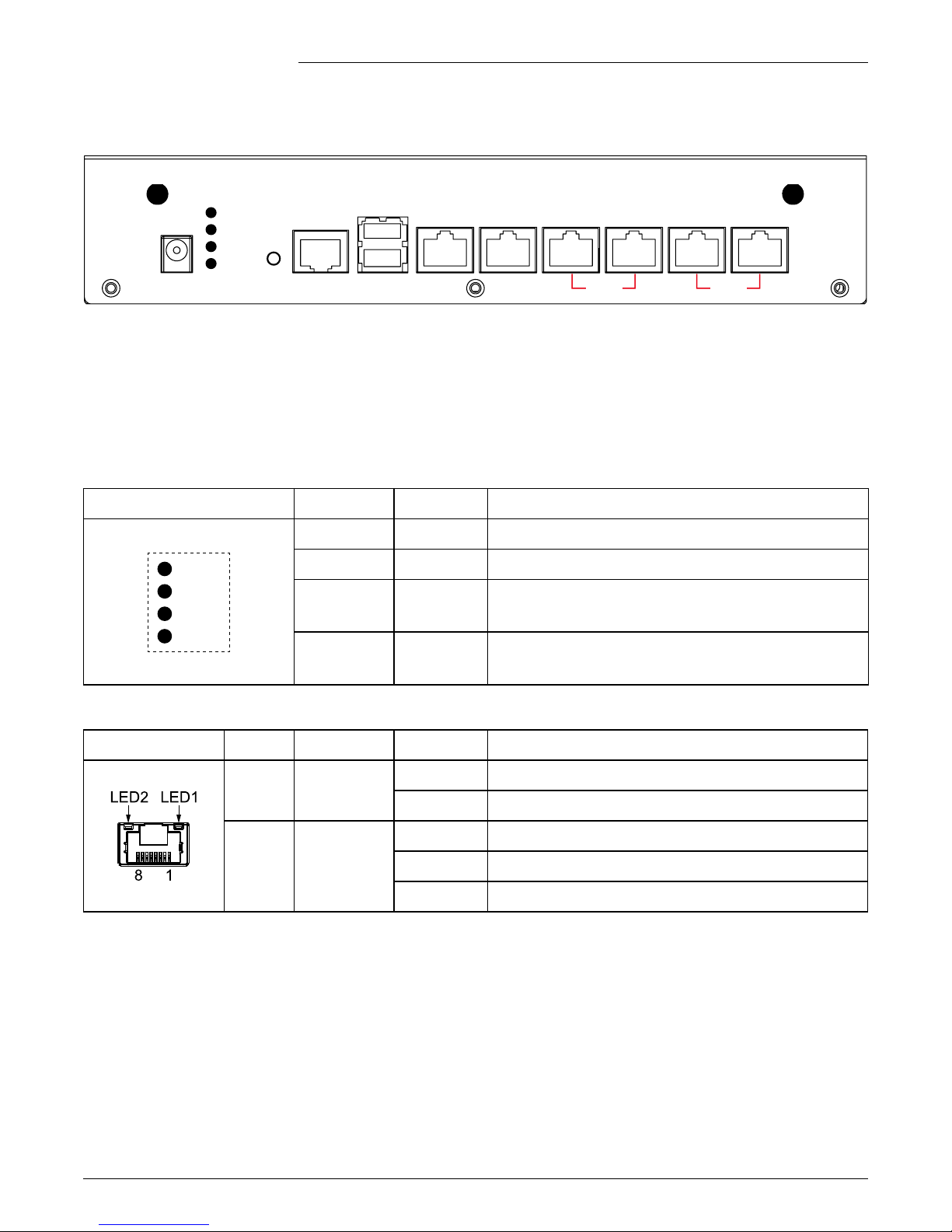
1.3.6. Rear I/O ..................................................................................................... 15
2. Components Assembly ................................................16
2.1. 2.5” HDD Installation ............................................................................................... 16
2.2. Memory/CF Card Installation................................................................................... 17
3. BIOS Settings...............................................................18
3.1. Main Setup .............................................................................................................. 18
3.2. Advanced Setup ...................................................................................................... 19
3.2.1. ACPI Settings ............................................................................................ 19
3.2.2. Super IO Conguration .............................................................................. 20
3.2.3. Hardware Monitor ...................................................................................... 21
3.2.4. Smart Fan Function ................................................................................... 22
3.2.5. LAN Bypass Control & WatchDog Settings ............................................... 23
3.2.6. Power Button Control................................................................................. 24
3.2.7. S5 RTC Wake Settings .............................................................................. 25
3.2.8. Serial Port Console Redirection................................................................. 26
3.2.9. CPU Congration....................................................................................... 27
3.2.10. PPM Conguration..................................................................................... 28
3.2.11. IDE Conguration ...................................................................................... 29
3.2.12. OS Conguration ....................................................................................... 30
3.2.13. CSM Conguration .................................................................................... 31
3.2.14. USB Conguration..................................................................................... 32
3.3. Chipset Setup.......................................................................................................... 33
3.3.1. North Bridge............................................................................................... 33
3.3.2. South Bridge .............................................................................................. 34
3.4. Security Setup ......................................................................................................... 35

AND-J190N2-C612, AND-J180N2-C612 User Manual
4
Acrosser Technology Co., Ltd.
3.5. Boot Setup............................................................................................................... 36
3.6. Save & Exit Setup ................................................................................................... 37
4. Driver and Utility Installation ......................................38
4.1. Driver CD Interface Introduction.............................................................................. 38
4.2. Driver Installation Page ........................................................................................... 40
4.3. Utility Installation Page ............................................................................................ 42
4.4. Application Installation Page ................................................................................... 45
4.5. Document Page....................................................................................................... 46
5. Software Installation and Programming Guide...........47
5.1. Introduction.............................................................................................................. 47
5.1.1. GPIO.......................................................................................................... 47
5.1.2. Watchdog................................................................................................... 47
5.1.3. LAN Bypass Subsystem ............................................................................ 47
5.2. File Descriptions...................................................................................................... 47
5.2.1. GPIO/Watchdog/LAN Bypass Subsystem ................................................. 47
5.3. API List and Descriptions ........................................................................................ 48
5.3.1. GPIO.......................................................................................................... 48
5.3.2. Watchdog................................................................................................... 48
5.3.3. LAN Bypass Subsystem ............................................................................ 48
6. FAQ ...............................................................................50
Q 1. Where can I nd the serial number of this product?................................................ 50

AND-J190N2-C612, AND-J180N2-C612 User Manual
5
www.acrosser.com
1. Introduction
The AND-J190N2-C612 or AND-J180N2-C612 is a networking Micro Box System with
Intel®Celeron®J1900 quad-core 2.00GHz, or J1800 dual-core 2.41GHz CPU, and 6x
or 4x GbE LAN ports supporting up to 2 pairs bypass function .
1.1. Specifications
System
Thermal Solution • 1x System FAN
CPU • AND-J190N2-C612: Intel®Celeron®Bay Trail J1900,
Quad-core, clock speed 2.00GHz
• AND-J180N2-C612: Intel®Celeron®Bay Trail J1800,
Dual-core, clock speed 2.41GHz
System Memory • Support DDR3L Only, (Max. capacity: 8GB)
• 1x 204-pin SO-DIMM socket (non-ECC)
BIOS • AMI UEFI BIOS
BIOS Function • Support SSID
Network Interface
Ethernet Chip • Intel®I211-AT
Ethernet • 6x PCIe x1 Intel GbE chip via RJ-45 Connectors
• 10/100/1000Mbps
LAN Bypass • 2-pair LAN Bypass
Bypass1: LAN3/LAN4
Bypass2: LAN5/LAN6
Storage
CF • 1x CF Socket
SATA • 1x SATAII Connector
• 1x SATAII Power (JST 2.54mm, 1x4 pin)
HDD • 1x 2.5” HDD Bay on top cover
Expansion I/O
Mini PCIe Slot • 1x Mini PCI-e slot (PCI-e Signal Only)

AND-J190N2-C612, AND-J180N2-C612 User Manual
6
Acrosser Technology Co., Ltd.
Others
Watchdog Timer • Software Programmable 0 ~ 255 seconds
(0=Disable Timer)
Battery • Lithium Battery, 3V 220mAH (CR2032)
Hardware Monitoring • CPU Voltage
• CPU Temperature
• System Temperature
• RTC Battery Voltage
• Fan Speed
Power Adapter • DC in 12V, 60W Adapter
OS Support • Windows 7 (32/64-bit)
• Linux Kernel 3.11 (32/64-bit) or above
Mechanical & Environment
Chassis Dimension • 235 x 150.5 x 44.5 mm
Operating Temperature • 0 ~ 40°C (32 ~ 104°F)
Storage Temperature • -20 ~ 80°C (-4 ~ 176°F)
Relative Humidity • 0 ~ 90% @40°C, non-condensing
1.2. Packing List
Check if the following items are included in the package.
1x AND-J190N2-C612 or AND-J180N2-C612 System
1x SATA Power Cable
1x SATA Cable
1x Console Cable (RJ45)
1x Driver CD
1x Power Adapter

AND-J190N2-C612, AND-J180N2-C612 User Manual
7
www.acrosser.com
1.3. System Dissection
1.3.1. Dimension
(Unit: mm)
151.5
235
44.5

AND-J190N2-C612, AND-J180N2-C612 User Manual
8
Acrosser Technology Co., Ltd.
1.3.2. Board Layout
LAN5
LAN4
LAN3
LAN2
LAN6
LAN1
CF1
CN14
CN15
FAN2
DC1
DC2
SATA_PWR1
P_B2
RST_B2
31
FAN1
LED2
LED1
CN18
CN12
CN9
CN17
USB2
VGA1
COM1
USB1
CN13
MINIPCIE1
LED_LAN6
LED_LAN5
LED_LAN4
LED_LAN3
LED_LAN2
LED_LAN1
BAT1
U1
BJ
A
53
1
BZ1
SATA 1
CLR_CMOS1
ATX1
How to identify the rst pin of a header or jumper?
Usually, there is a thick line or a triangle near the header’s or jumper’s pin 1.
The square pad found on the back of the motherboard is usually used for pin 1.

AND-J190N2-C612, AND-J180N2-C612 User Manual
9
www.acrosser.com
1.3.3. Jumper Settings
CMOS Memory Clearing Jumper
LAN5
LAN4
LAN3
LAN2
LAN6
LAN1
CF1
CN14
CN15
FAN2
DC1
DC2
SATA_PWR1
P_B2
RST_B2
31
FAN1
LED2
LED1
CN18
CN12
CN9
CN17
USB2
VGA1
COM1
USB1
CN13
MINIPCIE1
LED_LAN6
LED_LAN5
LED_LAN4
LED_LAN3
LED_LAN2
LED_LAN1
BAT1
U1
BJ
A
53
1
BZ1
SATA1
CLR_CMOS1
ATX1
CLR_CMOS1 Pin # Denition
1-2 (default) Normal
2-3 Clear CMOS
If you encounter the following,
a) CMOS data becomes corrupted.
b) You forgot the supervisor or user password.
you can recongure the system with the default values
stored in the ROM BIOS.
1.3.4. Onboard Headers/Connectors Pin Definition
ATX Power Input Connector
LAN5
LAN4
LAN3
LAN2
LAN6
LAN1
CF1
CN14
CN15
FAN2
DC1
DC2
SATA_PWR1
P_B2
RST_B2
31
FAN1
LED2
LED1
CN18
CN12
CN9
CN17
USB2
VGA1
COM1
USB1
CN13
MINIPCIE1
LED_LAN6
LED_LAN5
LED_LAN4
LED_LAN3
LED_LAN2
LED_LAN1
BAT1
U1
BJ
A
53
1
BZ1
SATA1
CLR_CMOS1
ATX1
ATX1
Pin # Denition Pin #Denition
1+ 3.3V 2+ 3.3V
3COM 4+ 5V
5COM 6+ 5V
7COM 8PWR_OK
9+ 5V_SBY 10 + 12V
11 + 3.3V 12 - 12V
13 COM 14 PWR_ON
15 COM 16 COM
17 COM 18 - 5V
19 + 5V 20 + 5V
DC 12V Power Input Connector
LAN5
LAN4
LAN3
LAN2
LAN6
LAN1
CF1
CN14
CN15
FAN2
DC1
DC2
SATA_PWR1
P_B2
RST_B2
31
FAN1
LED2
LED1
CN18
CN12
CN9
CN17
USB2
VGA1
COM1
USB1
CN13
MINIPCIE1
LED_LAN6
LED_LAN5
LED_LAN4
LED_LAN3
LED_LAN2
LED_LAN1
BAT1
U1
BJ
A
53
1
BZ1
SATA1
CLR_CMOS1
ATX1
DC2 Pin # Denition
1+ 12V IN
2+ 12V IN
3GND
4GND
Note: DC2 only support DC12V power input. Please
DO NOT use the ATX power connector on this
motherboard, as it will cause unpredictable
damage.

AND-J190N2-C612, AND-J180N2-C612 User Manual
10
Acrosser Technology Co., Ltd.
System LED Pin Header
LAN5
LAN4
LAN3
LAN2
LAN6
LAN1
CF1
CN14
CN15
FAN2
DC1
DC2
SATA_PWR1
P_B2
RST_B2
31
FAN1
LED2
LED1
CN18
CN12
CN9
CN17
USB2
VGA1
COM1
USB1
CN13
MINIPCIE1
LED_LAN6
LED_LAN5
LED_LAN4
LED_LAN3
LED_LAN2
LED_LAN1
BAT1
U1
BJ
A
53
1
BZ1
SATA1
CLR_CMOS1
ATX1
CN12 Pin # Denition Pin #Denition
1+ 3.3V 2Power LED#
3+ 3.3V 4HD LED#
5Bypass1
LED# -Green 6Bypass1
LED# -Red
7Bypass2
LED# -Red 8Bypass2
LED# -Green
9+ 3.3V
COM2 Connector
LAN5
LAN4
LAN3
LAN2
LAN6
LAN1
CF1
CN14
CN15
FAN2
DC1
DC2
SATA_PWR1
P_B2
RST_B2
31
FAN1
LED2
LED1
CN18
CN12
CN9
CN17
USB2
VGA1
COM1
USB1
CN13
MINIPCIE1
LED_LAN6
LED_LAN5
LED_LAN4
LED_LAN3
LED_LAN2
LED_LAN1
BAT1
U1
BJ
A
53
1
BZ1
SATA1
CLR_CMOS1
ATX1
CN18
(COM2) Pin # Denition Pin #Denition
1DCD# 2RXD
3TXD 4DTR#
5GND 6DSR#
7RTS# 8CTS#
9RI#
GPIO Connector
LAN5
LAN4
LAN3
LAN2
LAN6
LAN1
CF1
CN14
CN15
FAN2
DC1
DC2
SATA_PWR1
P_B2
RST_B2
31
FAN1
LED2
LED1
CN18
CN12
CN9
CN17
USB2
VGA1
COM1
USB1
CN13
MINIPCIE1
LED_LAN6
LED_LAN5
LED_LAN4
LED_LAN3
LED_LAN2
LED_LAN1
BAT1
U1
BJ
A
53
1
BZ1
SATA1
CLR_CMOS1
ATX1
CN17 Pin # Denition Pin #Denition
1SIO_ GPI15
(0XA00 Bit5) 2SIO_ GPI33
(0XA02 Bit3)
3SIO_ GPI35
(0XA02 Bit5) 4SIO_ GPI47
(0XA03 Bit7)
5GND 6SIO_ GPO11
(0XA00 Bit1, H) [1]
7SIO_ GPO16
(0XA00 Bit6, H) 8SIO_ GPO32
(0XA02 Bit2, H)
9SIO_ GPO50
(0XA04 Bit0, H) 10 + 3.3V [2]
12 N/C
Note: [1] “H” or “L” means the default voltage is High or Low level.
[2] The power on this Pin and GPIO output is 3.3V signaling by default, 5V is
available if specied (resistor selectable).

AND-J190N2-C612, AND-J180N2-C612 User Manual
11
www.acrosser.com
SATA Connector
LAN5
LAN4
LAN3
LAN2
LAN6
LAN1
CF1
CN14
CN15
FAN2
DC1
DC2
SATA_PWR1
P_B2
RST_B2
31
FAN1
LED2
LED1
CN18
CN12
CN9
CN17
USB2
VGA1
COM1
USB1
CN13
MINIPCIE1
LED_LAN6
LED_LAN5
LED_LAN4
LED_LAN3
LED_LAN2
LED_LAN1
BAT1
U1
BJ
A
53
1
BZ1
SATA1
CLR_CMOS1
ATX1
SATA1 Pin # Denition Pin #Denition
1GND 6SATA_RXP0
2GND 7SATA_RXN0
3SATA_TXP0 8GND
4SATA_TXN0 9GND
5GND
SATA Power Connector
LAN5
LAN4
LAN3
LAN2
LAN6
LAN1
CF1
CN14
CN15
FAN2
DC1
DC2
SATA_PWR1
P_B2
RST_B2
31
FAN1
LED2
LED1
CN18
CN12
CN9
CN17
USB2
VGA1
COM1
USB1
CN13
MINIPCIE1
LED_LAN6
LED_LAN5
LED_LAN4
LED_LAN3
LED_LAN2
LED_LAN1
BAT1
U1
BJ
A
53
1
BZ1
SATA1
CLR_CMOS1
ATX1
SATA_PWR1 Pin # Denition Pin #Denition
1+ 12V 2GND
3GND 4+ 5V
VGA Output Connector
LAN5
LAN4
LAN3
LAN2
LAN6
LAN1
CF1
CN14
CN15
FAN2
DC1
DC2
SATA_PWR1
P_B2
RST_B2
31
FAN1
LED2
LED1
CN18
CN12
CN9
CN17
USB2
VGA1
COM1
USB1
CN13
MINIPCIE1
LED_LAN6
LED_LAN5
LED_LAN4
LED_LAN3
LED_LAN2
LED_LAN1
BAT1
U1
BJ
A
53
1
BZ1
SATA1
CLR_CMOS1
ATX1
VGA1
Pin # Denition Pin # Denition
1GND 2VSYNC
3HSYNC 4GND
5RED 6GND
7GREEN 8GND
9BLUE 10 GND
11 DDC Data 12 DDC Clock

AND-J190N2-C612, AND-J180N2-C612 User Manual
12
Acrosser Technology Co., Ltd.
Debug Pin Header
LAN5
LAN4
LAN3
LAN2
LAN6
LAN1
CF1
CN14
CN15
FAN2
DC1
DC2
SATA_PWR1
P_B2
RST_B2
31
FAN1
LED2
LED1
CN18
CN12
CN9
CN17
USB2
VGA1
COM1
USB1
CN13
MINIPCIE1
LED_LAN6
LED_LAN5
LED_LAN4
LED_LAN3
LED_LAN2
LED_LAN1
BAT1
U1
BJ
A
53
1
BZ1
SATA1
CLR_CMOS1
ATX1
CN9
CN9
Pin # Denition Pin #Denition
1LFRAME# 2LAD3
3LAD2 4LAD1
5LAD0 6GND
7PCIRST 8CLOCK
9+ 3.3V
Fan Power Connector
LAN5
LAN4
LAN3
LAN2
LAN6
LAN1
CF1
CN14
CN15
FAN2
DC1
DC2
SATA_PWR1
P_B2
RST_B2
31
FAN1
LED2
LED1
CN18
CN12
CN9
CN17
USB2
VGA1
COM1
USB1
CN13
MINIPCIE1
LED_LAN6
LED_LAN5
LED_LAN4
LED_LAN3
LED_LAN2
LED_LAN1
BAT1
U1
BJ
A
53
1
BZ1
SATA1
CLR_CMOS1
ATX1
FAN1 (CPU_FAN1)
FAN2 (SYS_FAN1)
FAN2FAN1
Pin # Denition Pin #Denition
1GND 2+ 12V
3FAN Speed
Detection 4FAN Speed Control
LAN LED Pin Header
LAN5
LAN4
LAN3
LAN2
LAN6
LAN1
CF1
CN14
CN15
FAN2
DC1
DC2
SATA_PWR1
P_B2
RST_B2
31
FAN1
LED2
LED1
CN18
CN12
CN9
CN17
USB2
VGA1
COM1
USB1
CN13
MINIPCIE1
LED_LAN6
LED_LAN5
LED_LAN4
LED_LAN3
LED_LAN2
LED_LAN1
BAT1
U1
BJ
A
53
1
BZ1
SATA1
CLR_CMOS1
ATX1
CN13
Pin # Denition Pin #Denition
1LAN1_ACT# 2+ 3.3V
3LAN1_LINK_1G# 4LAN1_LINK_100M#
5LAN2_ACT# 6+ 3.3V
7LAN2_LINK_1G# 8LAN2_LINK_100M#
9LAN3_ACT# 10 + 3.3V
11 LAN3_LINK_1G# 12 LAN3_LINK_100M#
13 LAN4_ACT# 14 + 3.3V
15 LAN4_LINK_1G# 16 LAN4_LINK_100M#
17 LAN5_ACT# 18 + 3.3V
19 LAN5_LINK_1G# 20 LAN5_LINK_100M#
21 LAN6_ACT# 22 + 3.3V
23 LAN6_LINK_1G# 24 LAN6_LINK_100M#
25 GND 26 GND

AND-J190N2-C612, AND-J180N2-C612 User Manual
13
www.acrosser.com
Mini PCI Express Slot
LAN5
LAN4
LAN3
LAN2
LAN6
LAN1
CF1
CN14
CN15
FAN2
DC1
DC2
SATA_PWR1
P_B2
RST_B2
31
FAN1
LED2
LED1
CN18
CN12
CN9
CN17
USB2
VGA1
COM1
USB1
CN13
MINIPCIE1
LED_LAN6
LED_LAN5
LED_LAN4
LED_LAN3
LED_LAN2
LED_LAN1
BAT1
U1
BJ
A
53
1
BZ1
SATA1
CLR_CMOS1
ATX1
MINIPCIE1:
MINIPCIE1
CF Card, SO-DIMM Socket
LAN5
LAN4
LAN3
LAN2
LAN6
LAN1
CF1
CN14
CN15
FAN2
DC1
DC2
SATA_PWR1
P_B2
RST_B2
31
FAN1
LED2
LED1
CN18
CN12
CN9
CN17
USB2
VGA1
COM1
USB1
CN13
MINIPCIE1
LED_LAN6
LED_LAN5
LED_LAN4
LED_LAN3
LED_LAN2
LED_LAN1
BAT1
U1
BJ
A
53
1
BZ1
SATA1
CLR_CMOS1
ATX1
CF1: DIMM1:
CF1

AND-J190N2-C612, AND-J180N2-C612 User Manual
14
Acrosser Technology Co., Ltd.
1.3.5. Front I/O
• POWER: Front Panel Power Button
• USB:USB 3.0 Port
• LED LAN1~6: LED Indicators of LAN1 ~
LAN6
• LED: LED Indicators of HDD, Power, and
LAN status
LAN1 ~ LAN6 LED Display
LED LAN1~6 LED Function Light Status
Up Link
Green Link 1000Mbps
Red Link 100Mbps
Off Link 10Mbps
Down Activity Red Flashing when active
Off Not active
Status/HDD/Power LED Display
LED2 LED Light Status
POWER Green Power On
HDD Yellow HDD Status
BYPASS1 Green
Red
Green: Bypass1 in Normal Status
Red: Bypass1 in Bypass Status
BYPASS2 Green
Red
Green: Bypass2 in Normal Status
Red: Bypass2 in Bypass Status

AND-J190N2-C612, AND-J180N2-C612 User Manual
15
www.acrosser.com
1.3.6. Rear I/O
POWER
HDD
BYPASS1
BYPASS2
USB
LAN1
Consol
DC_12V IN
LAN2 LAN3 LAN4 LAN5 LAN6
RESET
Bypass2Bypass1
• DC_12V IN: 12V DC-in
• LED: LED Indicators of Power, HDD, and
LAN Bypass status
• RESET: Reset Button
• Consol: RJ45 COM Port
• USB: 2 USB 2.0 Ports
• LAN1 ~ LAN6:6 RJ45 LAN Ports
Status/HDD/Power LED Display
LED1 LED Light Status
POWER
HDD
BYPASS1
BYPASS2
USB
LAN1
Consol
DC_12V IN
LAN2 LAN3 LAN4 LAN5 LAN6
RESET
Bypass2Bypass1
POWER Green Power On
HDD Yellow HDD Status
BYPASS1 Green
Red
Green: Bypass1 in Normal Status
Red: Bypass1 in Bypass Status
BYPASS2 Green
Red
Green: Bypass2 in Normal Status
Red: Bypass2 in Bypass Status
RJ45 LAN Ports
LAN1 ~ LAN6 LED Function Light Status
LED1 Link Green Link 1000/100/10Mbps
Off No Link
LED2 Activity
Green Data Transferring at 1000Mbps
Yellow Data Transferring at 100Mbps
Off No Data, or Data Transferring at 10Mbps

AND-J190N2-C612, AND-J180N2-C612 User Manual
16
Acrosser Technology Co., Ltd.
2. Components Assembly
To install your components, you will have to remove the top cover rst:
Step 1: Disconnect the power input.
Step 2: Remove three screws that locks the top cover.
2.1. 2.5” HDD Installation
Step 1: Lock your disk with the screws that came with the disk.
Step 2: Connect the SATA power/signal cable each from the disk to the
[SATA_PWR1] and [SATA1] connector on mainboard.

AND-J190N2-C612, AND-J180N2-C612 User Manual
17
www.acrosser.com
2.2. Memory/CF Card Installation
Step 1: Carefully insert your Memory card into the [DIMM1] socket and push it
into the locked position.
Step 2: Carefully insert your CF card into the [CF1] socket.

AND-J190N2-C612, AND-J180N2-C612 User Manual
18
Acrosser Technology Co., Ltd.
3. BIOS Settings
To access the BIOS Setup:
1. After power on, press <Delete> button during the P.O.S.T. (Power-on Self-Test)
process.
2. Once you enter the BIOS Setup, the Main Menu will show up on the screen, in
which you can use the arrow keys (<>, <>, <>, <>) to move or select the
items, and press <Enter> button to accept or enter the sub-menu.
Note: Press <Delete> button to enter BIOS Setup program, Press <F7> button to show
BBS.
3.1. Main Setup
This page contains the basic information about the BIOS version, and you can set
the system date and time manually.
Aptio Setup Utility - Copyright (C) 2016 American Megatrends, Inc.
Version 2.17.1246. Copyright (C) 2016 American Megatrends, Inc.
→←: Select Screen
↑↓: Select Item
Enter: Select
+/-: Change Opt.
F1: General Help
F2: Previous Values
F3: Optimized Defaults
F4: Save & Exit
ESC: Exit
Main Advanced Chipset Security Boot Save & Exit
BIOS Information
BIOS Vendor
Core Version
Compliancy
Project Version
Build Date and Time
Memory Information
System Date
Ststem Time
Access Level
American Megatrends
5.010
UEFI 2.4; PI 1.3
J190/J180 010-002
07/25/2016 11:22:33
2048 MB DDR3
[Tue 08/02/2016]
[11:22:33]
Administrator
Set the Date. Use Tab to
switch between Date
elements.
• System Date
Set the system date. The date format is Week (Read-Only), Month/Day/Year. Use
<Tab> to switch the item between month, day and year. Either you can use the
<+>/<-> key to change the value, or use the number keys to enter a new value for
the date setting.
• System Time
Set the system time. The time format is Hour/Minute/Second. Use <Tab> to switch
the item between hour, minute, second. Either you can use the <+>/<-> key to
change the value, or use the number keys to enter a new value for the time setting.

AND-J190N2-C612, AND-J180N2-C612 User Manual
19
www.acrosser.com
3.2. Advanced Setup
Aptio Setup Utility - Copyright (C) 2016 American Megatrends, Inc.
Version 2.17.1246. Copyright (C) 2016 American Megatrends, Inc.
→←: Select Screen
↑↓: Select Item
Enter: Select
+/-: Change Opt.
F1: General Help
F2: Previous Values
F3: Optimized Defaults
F4: Save & Exit
ESC: Exit
Main Advanced Chipset Security Boot Save & Exit
ACPI Settings
Super IO Configuration
Hardware Monitor
Smart Fan Function
LAN Bypass Control & WatchDog Settings
Power Button Control
S5 RTC Wake Settings
Serial Port Console Redirection
CPU Configuration
PPM Configuration
IDE Configuration
OS Configuration
CSM Configuration
USB Configuration
System ACPI Parameters
3.2.1. ACPI Settings
Set system ACPI parameters.
Aptio Setup Utility - Copyright (C) 2016 American Megatrends, Inc.
Version 2.17.1246. Copyright (C) 2016 American Megatrends, Inc.
→←: Select Screen
↑↓: Select Item
Enter: Select
+/-: Change Opt.
F1: General Help
F2: Previous Values
F3: Optimized Defaults
F4: Save & Exit
ESC: Exit
Advanced
ACPI Settings
Enable ACPI Auto Conf
ACPI Sleep State
[Disabled]
[Suspend Disabled]
Enables or Disables
BIOS ACPI Auto
Configuratuon.

AND-J190N2-C612, AND-J180N2-C612 User Manual
20
Acrosser Technology Co., Ltd.
• Enable ACPI Auto Conguration
Enables or disables the BIOS ACPI auto conguaton.
• ACPI Sleep State
Select the highest ACPI sleep state the system will enter when the SUSPEND button
is pressed.
3.2.2. Super IO Configuration
Set System super IO chip parameters.
Aptio Setup Utility - Copyright (C) 2016 American Megatrends, Inc.
Version 2.17.1246. Copyright (C) 2016 American Megatrends, Inc.
→←: Select Screen
↑↓: Select Item
Enter: Select
+/-: Change Opt.
F1: General Help
F2: Previous Values
F3: Optimized Defaults
F4: Save & Exit
ESC: Exit
Advanced
Super IO Configuration
Super IO Chip
COM1
COM2
Set Parameters of
Serial Port 1
• COM1
Set parameters of Serial Port 1.
• COM2
Set parameters of Serial Port 2.
This manual suits for next models
1
Table of contents
Other Acrosser Technology Industrial PC manuals

Acrosser Technology
Acrosser Technology AR-V6002FL User manual

Acrosser Technology
Acrosser Technology AR-ES5495 User manual

Acrosser Technology
Acrosser Technology ANR-J190N2-C612 User manual

Acrosser Technology
Acrosser Technology AR-ES5430FL User manual

Acrosser Technology
Acrosser Technology ACS-N0831FLUD User manual

Acrosser Technology
Acrosser Technology AR-V5430FL User manual