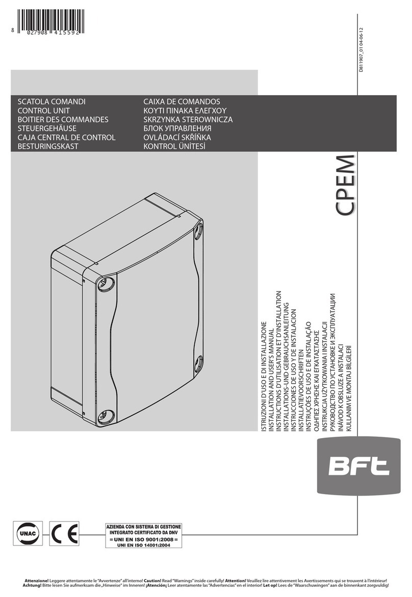
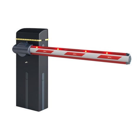
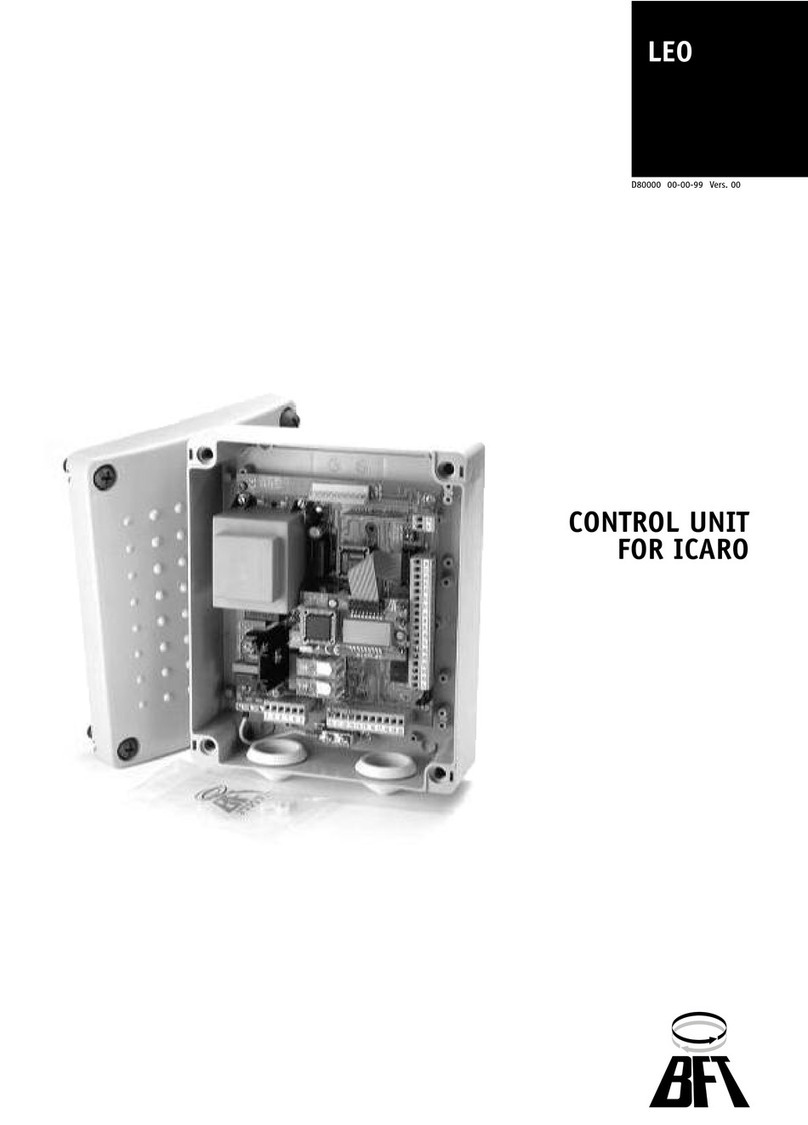
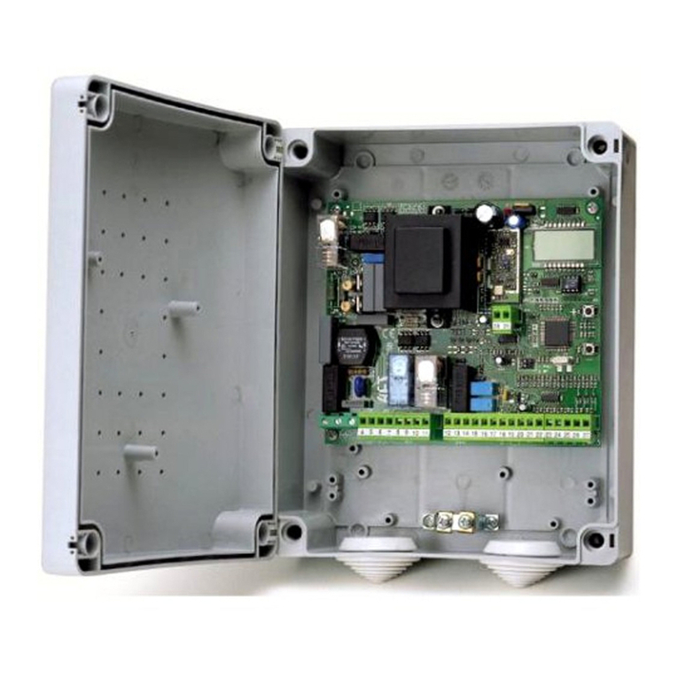
BFT CSB Xtreme (1.2) User manual

CENTRALE DI COMANDO pag. 3
MANUALE D’INSTALLAZIONE ED USO
CONTROL UNIT pag. 17
INSTALLATION AND OPERATION MANUAL
IT
EN
CSB Xtreme (1.2)

- 17 -
Contents
Page
1. INTRODUCTION 18
2. MAIN CHARACTERISTICS 18
3. TECHNICAL SPECIFICATIONS 19
4. INSTALLATION SAFETY 19
5. PRELIMINARY OPERATIONS 19
6. INPUT AND OUTPUT FUNCTIONALITY AND CONNECTIONS 19
6.1 J1 CONTROL UNIT POWER SUPPLY 19
6.2 J4 FLASHING LIGHT OUTPUT 19
6.3 J5 OUTPUTS/ACCESSORIES POWER SUPPLY 19
6.4 J6 ENCODER/INPUTS 20
6.5 J7 INPUTS/ANTENNA 20
6.6 J8 BOOM LIGHTS CONNECTOR 21
6.7 J10
E
XPANSION CONNECTOR 21
6.8 J12 RADIO PROGRAMMER CONNECTOR 21
7. INVERTER CONNECTIONS 21
7.1 INVERTER 21
7.2 J2 POWER SUPPLY 21
7.3 M MOTOR 21
7.4 J9 INVERTER SIGNALS 21
8. PROGRAMMING 22
8.1 BASIC FUNCTIONS 22
8.2 1ST LEVEL PROGRAMMING 23
8.3 2ND LEVEL PROGRAMMING 24
8.4 3RD LEVEL PROGRAMMING 25
8.5 4TH LEVEL PROGRAMMING 26
9. RADIO RECEIVER 27
9.1 RECEIVER TECHNICAL SPECIFICATIONS 27
9.2 RADIO CHANNEL FUNCTIONALITY 27
9.3 ANTENNA INSTALLATION 27
9.4 MANUAL PROGRAMMING 27
9.5 SELF-LEARNING MODE PROGRAMMING 27
10. WARNINGS 27
TABLE A 28
11. CONTROLLED ENTRY AND AUTOMATIC EXIT 29
12. TROUBLESHOOTING GUIDE 30

- 18 -
Control unit
EN
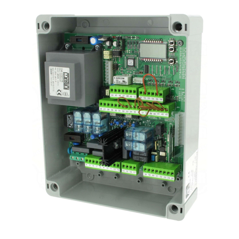
The control unit has been developed to control automatic single-phase barriers with inverter-driven three-phase motor.
1. INTRODUCTION
- Microprocessor logic
- LEDs displaying inputs/outputs status
- Integrated radio receiver 433.92MHz, 2 channels, 2 048 codes
- TCP/IP module and RS485 module (Option)
2. MAIN CHARACTERISTICS
F
J10
J9
J6J5
J12
J8
J2
J3
J4
J1
F2
F1
F3
F4
J7
J11
K2 K3 K4 K5
PR2
K1
DL
PR1
= Electrical connections congured at the factory.
J1: Control unit power supply
J2: Inverter power supply
J3: Transformer connector
J4: Flashing light output
J5: Outputs/accessories power supply
J6: Encoder/inputs
J7: Inputs/antenna
J8: Boom lights connector
J9: Inverter signals
J10: Expansion connector
J12:
Radio programmer connector
DL: 3-digit LED display
START: “START” control button
F1: Transformer primary fuse: 500 mAT (230Vac) - 1 AT (115Vac) 5x20mm
F2: Line fuse (control board and inverter): 4 AT (230Vac) - 8 AT (115Vac) 5x20 mm
F3, F4: Transformer secondaries fuses: 2 AT 5x20mm
F, - , + : Programming push buttons
PR1, PR2:
Radio receiver
programming push buttons
- 3-digit display for programming and system status
- Up to 4 congurable outputs
- Radio programmer connector
- Built-in heater for cold climates (Termon)
ANT
SHIELD
START
PDM
OPEN
CLOSE
COM
FTC
STOP
8k2
COM
FCA
FCC
OUT2
OUT3
OUT4
OUT5
+V
SIG.
GND
ENCODER
INVERTER
CH2 RX
24Vac1
24Vac2
FRAC
UPS
J7
J6
FWD
REV
B A
GND
COM
J9
J5J1
RS 485 OUT
L N
J2
230Vac
50-60Hz
OUT
LAMP
230Vac
40W max
230 Vac
INVERTER
N L
ENGLISH

- 19 -
Control unit
EN
6.3 J5 OUTPUTS/ACCESSORIES POWER SUPPLY
6.1 J1 CONTROL UNIT POWER SUPPLY
In order to reach the level of safety required by current regulations, follow these prescriptions carefully.
1) Make all the connections in the terminal block after carefully reading the instructions given in this manual and observing the general
rules and technical standards concerning electrical systems installations.
2) Always t an omnipolar circuit breaker with a contact gap of at least 3 mm.
3) Install a dierential circuit breaker with a threshold of 30 mA.
4) Check the eectiveness of the protective earth and connect to it all the parts of the automation tted with a terminal or grounding
cable.
5) Fit at least one external warning device, such as a trac light or ashing light, along with a warning or danger sign.
6) Fit all the safety devices required by the type of installation, taking into consideration the risks it can cause.
7) Separate in the ducts the power lines (1.5 mm2 min. section) from the low-voltage signal lines (0.5 mm2 min. section).
230Vac 50/60Hz power supply.
Connect the LINE and NEUTRAL as shown on the board. Use cable type H07RN-F 2x1.5+E min.
Connect the yellow/green EARTH wire of the power supply mains to the earth terminal of the appliance.
6. INPUT AND OUTPUT FUNCTIONALITY AND CONNECTIONS
OUT24
Output 24Vac, 1A max
OUT2
Programmable dry relay output, max. 500mA 24 Vac/dc (parameter - level 2)
OUT3
Programmable dry relay output, max. 500mA 24 Vac/dc (parameter - level 2)
OUT4
Programmable dry relay output, max. 500mA 24 Vac/dc (parameter - level 2)
OUT5/CH2 RX
Programmable dry relay output, max. 500mA 24 Vac/dc or N.O. output of the 2nd radio receiver channel
(parameter - level 2)
OUT2
OUT2
OUT3
OUT3
OUT4
OUT4
CH2
RX
24 Vac
4. INSTALLATION SAFETY
3. TECHNICAL SPECIFICATIONS
- Power supply:......................................................230Vac ±10%, 50/60Hz (115Vac on request)
-
Flashing light output
:...............................................................................................230Vac; 40W max
- Accessory output:...........................................................................................24Vac; 24W - 1A max
Barriers with standard booms are automatically selected. For special booms (barrier 35 only), before operating the automation,
make sure to have correctly selected the barrier/boom type as follows:
- Press and hold down buttons F and + for 5 seconds.
- Select the barrier/boom type using buttons +/-.
- Press together F and + to conrm.
- Only select the actual barrier/boom being used:
The Company is not liable for injury to people or animals or damage to things in the case of wrong selection of the barrier.
Selecting wrong barrier/boom voids warranty.
5. PRELIMINARY OPERATIONS
6.2 J4 FLASHING LIGHT OUTPUT
OUT
LAMP
Output 230Vac, 40W max.
LN
OUT5
OUT5
BARRIER TYPE SELECTION
MAXIMA ULTRA 68 (auto select) ATM 90° boom (ULTRA 35 only)
MAXIMA ULTRA 35 (auto select) ATM 180° boom (ULTRA 35 only)
Carbon boom (ULTRA 35 only)
ENGLISH

- 20 -
Control unit
EN
6.4 J6
ENCODER/INPUTS
6.5 J7
INPUTS/ANTENNA
ENCODER
Supplied already wired. Encoder can trigger in the closing movement only, when the boom hits an obstacle.
Select the desired behaviour by programming the parameter - level 1.
+V terminal can be used for powering additional sensors (16Vdc not stabilized-100mA max)
FRAC
N.C. additional safety input for swinging boom sensor.
When activated (open) it stops the automation immediately. Subsequent START always cause reopening.
UPS
UPS status input.
To be connected to smart UPS with status output, active-high during mains failure.
The control unit has also an internal detector that works with simpler square-wave and quasi-sinusosidal UPS. With
these simpler UPS there is no need to use this input.
START
N.O. input for controlling the automation according to four-step logic: open-stop-close-open.
PDM INPUT
Programmable input, parameter-level 3.
This signal can be duplicated on an programmable output (see OUT2, 3, 4, 5).
OPEN
N.O. input - opens the boom.
This input has priority over CLOSE command and can be kept always activated until necessary. Connect loop detectors,
clocks, daily or weekly timers here, where and if necessary.
FTC
COM
STOP
COM
FCA
COM
FCC
COM
START
COM
PDM
COM
OPEN
COM
CLOSE
COM
UPS
+V
BROWN
BLACK
BLUE
SHIELD
ANT
CLOSE
N.O. input for closing. It allows the automation to be closed only if the safety devices have not triggered.
Operating mode programmable with parameter -level -3.
FTC
N.C. safety input (photocell). Enter the programme wanted by programming the -level-1 parameter. It triggers only
in the closing phase; it never triggers in opening.
STOP
N.C. safety input. When activated it stops the automation instantly and a subsequent start always cause reopening.
During pause time (PAUSE trimmer) a stop command disables automatic reclosing, leaving the bar open waiting for
commands. NOTE: The hatch microswitch is already connected to this input.
8k2
Multi-purpose analog input. For TERMON heater see paragraph 8.3.
FCA
Limit switch N.C. input in opening. When activated the opening travel nishes.
FCC
Limit switch N.C. input in closing. When activated the closing travel nishes.
ANTENNA
Antenna connection for the integrated receiver
8k2
COM
SIG.
GND
+ V
BROWN
BLACK
BLUE
GND
FRAC
+ V
ENGLISH

- 21 -
Control unit
EN
7.1 INVERTER
6.8 J12
RADIO PROGRAMMER CONNECTOR
7. INVERTER CONNECTIONS
CONTROL UNIT
230Vac 50/60Hz with internal protection and fuse.
INVERTER
CONTROL UNIT
INVERTER
7.4 J9
INVERTER SIGNALS
7.2
J2 POWER SUPPLY
7.3 MOTOR
M
CC: Brown
F: Yellow
R: White
B: Gray
A: Pink
GND: Green
COM: Brown
FWD: Yellow
REV: White
NL
6.6 J8
BOOM LIGHTS CONNECTOR
6.7 J10
EXPANSION CONNECTOR
.
.
.
COM+
GRN
RED
.
.
.
J2
J9
M
FLA
OUT NO CC F RS1 S2 P24
FLB FLC CC VI P5 FM
BA
RS 485
GND
COM
FWD
REV
OUT
J9
TCP/IP
SC RS485
ENGLISH

- 22 -
Control unit
EN
8. PROGRAMMING
8.1 BASIC FUNCTIONS
To access programming, press button Ffor 2 seconds.
Programming is divided into 4 levels.
To go to the next level keep key Fpressed and press the +key (Sequence 1-2-3-1.......).
After selecting the level wanted, press push button Fto display the functions available in consecutive order. Each time F is pressed it
corresponds to a function ( - - - .....)
With the function set, use the +or -key to change the values of the parameters ( +: ---... / -: ...---).
The changes made to the parameters are active immediately but will be saved when exiting the menu, selecting the function with
key F.
PLEASE NOTE: If there is a black out when programming, all changes will be lost.
F-+
F
F
2nd level
=arm closed
F
F
F
F
F
F
F
F
F
F
F
FF+
+
+
+
-
-
-
+
+
+
+
+
+
+
+
x 2”
x 2” x 5 x 3x 4
1st level
programming
Selects each single
1st level function
(see table par.8.2)
Selects each single
2nd level function
(see table par.8.3)
Selects each single
4th level function
(see table par.8.5)
Changes the values
of each single 1st
level function
(see table par.8.2)
Changes the values
of each single 2nd
level function
(see table par.8.3)
Changes the values
of each single 4th
level function
(see table par.8.5)
“”function
Exit and save
programming
2nd level
programming
4th level
programming
Selecting Output2 on closed arm:
ABC D E
Example:
ENGLISH

- 23 -
Control unit
EN
8.2 1ST LEVEL PROGRAMMING
Par Function Settable data
Selects the functio-
ning logic. (see notes
after the table)
: Hold-to-run
: Semi automatic
: Automatic
Close input congu-
ration (see notes after
the table)
: Standard close input
: Close-when-released input
: The close command acts as a release closing and safety function.
Photocells
: When closing it stops and waits for disengaged photocell commands
: When closing it stops; reclosing after 1’’ when the photocell is disengaged
: When closing it reopens; reclosing after 1’’ when the photocell is disengaged
: When closing it reopens; reclosing after 5’’ when the photocell is disengaged
: When closing it reopens; reclosing when the photocell is disengaged
: When closing it reopens and waits for disengaged photocell commands
Encoder
: Excluded
: When closing it stops and waits for commands
: When closing it reopens and waits for commands
: When closing it reopens, reclosing after 5 seconds
Encoder sensitivity (minor - major)
Warning ash
: Excluded
: Prior to each movement on a congured output (see parameters ,,,
in the 2nd level table)
: Prior to each movement on a congured output and on the arm lights
Arm lights
: Flashing red light when moving, o red light when the arm is closed and open.
: Flashing red light when moving, on red light when the arm is closed and o
when the arm is open.
: Flashing red light when moving and with the arm closed, on red light when
stopped and on green light when the arm is open.
: Flashing red light when moving, o red light when the arm is closed and on
green light when the arm is open
: Flashing red light when moving, on red light when the arm is closed and on
green light when the arm is open
Pause time (expres-
sed in seconds) -
Resetting default
parameters. (see notes
after the table)
: No resetting
: Resetting the default parameters and arm type
Exiting the menu/
saving
Exit programming and view machine status
(see notes St automation status display)
Description of level 1 parameters
·: Functioning logic
- Hold-to-run: The automation works when the commands are held down. The start command opens once and closes once.
- Semi automatic: The automation works with jog commands, without automatic reclosing. Hence, when fully open, to control closing
you need to act on the start or close command respectively.
- Automatic: The automation works in jogs. When the opening manoeuvre is completed in the standard cycle, automatic reclosing is
activated after the pause time set (parameter ).
·: Close conguration
- : Close-when-released input
This mode has been developed so the arm closes automatically only when the vehicle has completely passed by the photocell or
magnetic detector (the most suitable accessories for this purpose).
The following table gives the 1st level functions and the single settable parameters.
= DEFAULT value set in factory. = parameter value set during installation: must be indicated if
DEFAULT value is modied.
ENGLISH

- 24 -
Control unit
EN
8.3 2ND LEVEL PROGRAMMING
: Idle
:
:
:
Opening
Stop opening limit switch
Stop opening
:
:
:
Closing
Stop closing limit switch
Stop closing
: N/A
Connect the N.O. contact of the detector or photocell to the Close contact terminals.
If the vehicle is on the detector or in front of the photocell it does not cause immediate closing but rather you have to wait for the
signal to be released.
- : The close command acts as a release closing and safety function.
When closing, the close command engaging stops the automation. When disengaged the barrier resumes closing.
·:Default
- To reset the default parameters, set parameter on 1 and exit the menu’.
·
:Automation status display
- During operation, the control unit displays automation status so the installer is able to follow the logical ow of the board.
The status are:
The following table gives the 2nd level functions and the single settable parameters.
= DEFAULT value set in factory. = parameter value set during installation: must be indica-
ted if DEFAULT value is modied.
:
:
:
Stop due to photocell triggering
Opening due to photocell triggering
Photocell triggering pause
:
:
:
Stop due to encoder triggering
Opening due to encoder triggering
Pause due to encoder triggering
:
:
Maximum working time in opening reached
Maximum working time in closing reached
Par Function Settable data
Maximum operating time (sec.)
-
Request for maintenance
: disabled
: active on the congured outputs
: active on the congured outputs and the bar lights ash twice
Programming maintenance
cycles in thousands
Programming maintenance
cycles in millions ...
Output 2, Output 3,
Output 4, Output 5
: request for maintenance
: photocell triggering
: encoder triggering
: PDM contact actuated
: arm closed
: arm open
: stop contact actuated
: warning ash
: Arm locking device
: open triggering
: contatto close attivato
: start triggering
: FRAC triggering
: UPS triggering
: second radio channel triggering (only OUT 5)
Termon
: Disabled
: Enabled and always active
: Enabled when needed by means of NTC sensor connected between
8k2 and COM input terminal
ENGLISH

- 25 -
Control unit
EN
8.4 3ND LEVEL PROGRAMMING
Description of level 2 parameters
·: Request for maintenance
: the request for maintenance is not active.
: at the end of the countdown, by means of counters and , one of the programmed outputs is activated (see parameter
,,,)
: at the end of the countdown, by means of counters and , one of the programmed outputs is activated (see parameter
,,,) and the bar lights ash twice.
·and: Programming maintenance cycles in thousands and millions
Thanks to the combination of the two parameters the countdown can be set after which a request for maintenance is signalled.
Thousands can be set with the parameter, millions with the parameter.
Example: to set 275 000 maintenance manoeuvres set on 0.2 and on 75.
The value displayed in the parameters updates along with the manoeuvres.
·: TERMON (integrated motor heater system).
: system is always ON. Must be used only with maximum ambient temperature less than +10°C
WARNING: ambient temperatures >10°C may cause overheating and damages to the motor, not covered by warranty
: system is actived depending on motor temperature, measured by a NTC sensor (option). In case of NTC failure, system reverts to
setup
·: UPS
UPS TYPE
Square-wave or quasi-sine wave UPS Internal detector, UPS input not connected
Pure-sinusoidal wave UPS with mains failure output Connect mains failure output to UPS input
Pure-sinusoidal wave UPS without mains failure output Use 230Vac relais, bobbin connected to mains supply, close contacts to UPS input
·Arm locking device conguration:
To use the arm locking device, connect the enabling contact to OUT2 or OUT3 or OUT4 or OUT5 and set the corresponding
parameter ,, or to . Set advance electric lock disengagement ( -3nd level)
The following table gives the 3rd level functions and the single parameters.
= DEFAULT value set in factory. = parameter value set during installation: must be indicated if
DEFAULT value is modied.
Par Function Settable data
UPS
: disabled
: enabled, opens automatically during mains failure
: enabled, closes automatically during mains failure
ATTENTION:THIS SELECTION MAY BE DANGEROUS
Exiting the menu/saving Exit programming and view machine Status (see notes automation Status
display after the 1st level table)
Par Function Settable data
Advanced setup
: no advanced setup
: N/A
: controlled entry and automatic exit
PDM dynamic input polarity
: input N.O.
: input N.C.
Output 2 polarity
Output 3 polarity
Output 4 polarity
Output 5 polarity
: N.O.
: N.C.
Advance electric lock disenga-
gement : 0,5s - : 1s - : 1,5s - : 2s - : 2,5s - : 3s
Opening speed (%)
- (MAXIMA ULTRA 68, ATM 90°, ATM 180°)
- (MAXIMA ULTRA 35, Carbon)
ENGLISH

- 26 -
Control unit
EN
The following table gives the 4rd level functions and the single parameters.
= DEFAULT value set in factory. = parameter value set during installation: must be indicated
if DEFAULT value is modied.
8.5 4TH LEVEL PROGRAMMING
Descrizione parametri livello 4
·:
Setting communication protocol.
Set value always same to Master and Slave.
·:
Impostazione U-LINK mode.
·:
Setting U-LINK adress.
Par Function Settable data
Communication protocol
: disabled
: U-LINK
: Modbus/RTU
U-LINK mode
: Slave
: Master
: Slave for opposing barriers
: Master for opposing barriers
U-LINK adress
Modbus/RTU ID
: For Slave
: For Master
MODBUS RTU speed
: 19 200 band
: 38 400 band
·:
Setting Modbus/RTU ID.
·:
Setting MODBUS RTU speed
Set value always same to Master and Slave.
Description of level 3 parameters
·, , , :Output polarity
Output polarity: The outputs can be congured as N.O. or N.C. but, in the event of a blackout the contacts open anyway.
·:Velocity selection input
By enabling this parameter bar speed can be adjusted via the PDM input.
If the PDM is activated and parameter enabled the barrier moves at a speed equal to 60% of maximum speed, both when ope-
ning and closing.
·:Advance electric lock disengagement
This parameter adjusts the delay between electo-lock deactivation and engine start , to allow the resetting of the residual magneti-
sm of the electro lock.
·:Advanced setup
This parameter enables the use of special congurations to cater for specic necessities.
N/A.
Controlled entry and automatic exit (see paragraph 11).
·: Swinging boom sensor input N.C.
swingin boom sensor not mounted or disabled
automation stops immediately in case of swinging boom opened
Closing speed (%)
- (MAXIMA ULTRA 68, ATM 90°, ATM 180°)
- (MAXIMA ULTRA 35, Carbon)
Speed selection input
: Disabled
: Enabled
Swinging boom sensor input
: swinging boom not mounted or disabled
: swinging boom sensor mounted and activated N.C.
Exiting the menu/saving Exit programming and view machine status (see notes St automation
status display after the 1st level table)
ENGLISH
- 27 -
Control unit
EN
T2
T1
T3 T4
It is recommended to make an installation which has all the accessories necessary to ensure operation according to current provisions,
always using genuine devices.
This equipment must be installed and used in strict compliance with the manufacturer’s instructions. The manufacturer cannot be held
responsible for any damage deriving from improper or unreasonable use.
The constructor disclaims all liability for any inaccuracies contained in this booklet and reserves the right to make changes at any time
without any prior notice whatsoever.
This mode is used to copy the keys of a transmitter already stored in the receiver memory, without accessing
the receiver.
The rst transmitter is to be memorised in manual mode (see paragraph 9.4).
a) Press hidden key on the transmitter already memorised.
b) Press key T on the transmitter already memorised, which is also to be attributed to the new transmitter.
c) Within 10 s., press hidden key on the new transmitter to be memorised.
d) Press key T to be attributed to the new transmitter.
e) To memorise another transmitter, repeat the procedure from step (c) within a maximum time of 10
seconds, otherwise the receiver exits the programming mode.
f ) To copy another key, repeat from step (a), having waited for the receiver to exit the programming mode
(or after disconnecting the receiver from the power supply).
9.5 SELF-LEARNING MODE PROGRAMMING
Hidden key
10. WARNINGS
In the case of standard installations where no advanced functions are required, it is possible to proceed to manual
storage of the transmitters, making reference to programming table A and to the example for basic programming.
1) If you wish the transmitter to activate output 1, press pushbutton PR1, otherwise if you wish the
transmitter to activate output 2, press pushbutton PR2.
2) When LED DL1 starts blinking, press hidden key on the transmitter, LED DL1 will remain continuously lit.
3) Press the key of the transmitter to be memorized, LED DL1 will ash quickly to indicate that it has been
memorized successfully. Flashing as normal will then be resumed.
4) To memorize another transmitter, repeat steps 2) and 3).
5) To exit memorizing mode, wait for the LED to go o completely or press the key of a remote control that
has just been memorized.
IMPORTANT NOTE: ATTACH THE ADHESIVE KEY LABEL TO THE FIRST MEMORISED TRANSMITTER (MASTER).
In the case of manual programming, the rst transmitter assigns the key code to the receiver; this code is necessary
in order to carry out subsequent cloning of the radio transmitters.
9.4 MANUAL PROGRAMMING
9. RADIO RECEIVER
antenna cable RG58
9.1 RECEIVER TECHNICAL SPECIFICATIONS
- Max. n° of radio transmitters that can be memorized: 2 048
- Frequency: 433.92MHz
- Code by means of: Rolling-code algorithm
- N° of combinations: 4 billion
9.2 RADIO CHANNEL FUNCTIONALITY
Channel 1: Start command
Channel 2: Closes the relay contact on the terminal block J5 “CH2 RX”
9.3 ANTENNA INSTALLATION
Use an antenna tuned to 433MHz. Con-
nect the tuned antenna to the antenna
terminals using RG58 coaxial cable.
SHIELD
ANT
FCC
J7
Hidden key
ENGLISH
- 28 -

- 29 -
Control unit
EN
1600 2000 2000
4000
S2
S1 1000
S2
S1
000000
S2
S1
S2
S1
This solution is recommended when you want to enter a reserved area in both directions. To enter, transit is allowed by means of a reco-
gnition command while exiting is automatic.
EXIT
When coil S1 is cleared, the barrier
starts closing instantaneously.
The vehicle approaches the reserved
area. When the coil S2 is occupied,
barrier opening is enabled.
If the coil S1 is not occupied within the
pause time, the barrier closes again.
When coil S1 is cleared, the barrier
starts closing instantaneously.
DIMENSIONS
Loop S1 also perform as safety function not permitting the barrier closure as long as barrier is occupied.
ENTRY
The recognition system enables bar-
rier opening.
If the coil S1 is not occupied within the
pause time, the barrier closes again.
11. CONTROLLED ENTRY AND AUTOMATIC EXIT
S2
S1
PARAMETER DATA DESCRIPTION
Automatic
The close control closes when pressed and released, and also functions as a safety system.
Advanced Setup: controlled entry and automatic exit
- Connect the coil S1 to the CLOSE input.
- Connect the N.O. contact of the S2 loop receiver to input START.
- The dimensional values of the loops are only approximate.
We suggest installing the“RME 2”metal mass detector.
- Only use recognition systems other than remote control units (badge readers, video camera systems with license plate
recognition etc.) with a potential free output, which must be connected to the OPEN input.
*
ENGLISH

- 30 -
Control unit
EN
C
A B
Default setting
Pulling this switches
for reduces the
leakage current
12. TROUBLESHOOTING GUIDE
- In the case of a malfunction, check that the correct barrier was selected (paragraph 5)
- Dual ashing of the cover lights. Indicates that scheduled maintenance is required. Check the parameters -2ND level,
-2ND level, -2ND level.
- Current from to ground leakage problem: the Inverter have a built-in high-attenuation noise lter and are grounded via a capacitor.
A switch makes to reduce leakage current from to ground. The reducing the load means though non-conformity with the EMC
standard on the inverter itself. Do switching with the power o.
ENGLISH
- 31 -
Dati impianto • Plant data
Installatore
Installer
Cliente
Customer
Matricola
Serial number
Data installazione
Installation date
Data attivazione
Activation date
Nr. Data • Date Descrizione intervento • Intervention description Firme •Signatures
1
Tecnico • Technician
Cliente • Customer
2
Tecnico • Technician
Cliente • Customer
3
Tecnico • Technician
Cliente • Customer
4
Tecnico • Technician
Cliente • Customer
5
Tecnico • Technician
Cliente • Customer
6
Tecnico • Technician
Cliente • Customer
7
Tecnico • Technician
Cliente • Customer
8
Tecnico • Technician
Cliente • Customer
9
Tecnico • Technician
Cliente • Customer
10
Tecnico • Technician
Cliente • Customer
REGISTRO DI MANUTENZIONE
MAINTENANCE LOG

Bft Spa
Via Lago di Vico, 44
36015 Schio (VI)
T +39 0445 69 65 11
F +39 0445 69 65 22
Æwww.bft.it
SPAIN
BFT GROUP ITALIBERICA DE
AUTOMATISMOS S.L.
08401 Granollers - (Barcelona)
www.bftautomatismos.com
FRANCE
AUTOMATISMES BFT FRANCE
69800 Saint Priest
www.bft-france.com
GERMANY
BFT TORANTRIEBSSYSTEME Gmb H
90522 Oberasbach
www.bft-torantriebe.de
UNITED KINGDOM
BFT AUTOMATION UK LTD
Stockport, Cheshire, SK7 5DA
www.bft.co.uk
IRELAND
BFT AUTOMATION LTD
Dublin 12
BENELUX
BFT BENELUX SA
1400 Nivelles
www.bftbenelux.be
POLAND
BFT POLSKA SP. Z O.O.
05-091 ZĄBKI
www.bft.pl
CROATIA
BFT ADRIA D.O.O.
51218 Drazice (Rijeka)
www.bft.hr
PORTUGAL
BFT SA-COMERCIO DE
AUTOMATISMOS E MATERIAL DE
SEGURANCIA
3020-305 Coimbra
www.bftportugal.com
CZECH REPUBLIC
BFT CZ S.R.O.
Praha
www.bft.it
TURKEY
BFT OTOMATIK KAPI SISTEMELERI
SANAY VE
Istanbul
www.bftotomasyon.com.tr
RUSSIA
BFT RUSSIA
111020 Moscow
www.bftrus.ru
AUSTRALIA
BFT AUTOMATION AUSTRALIA
PTY LTD
Wetherill Park (Sydney)
www.bftaustralia.com.au
U.S.A.
BFT USA
Boca Raton
www.bft-usa.com
CHINA
BFT CHINA
Shanghai 200072
www.bft-china.cn
UAE
BFT Middle East FZCO
Dubai
cod. 035755-B rev. 002 date 12-12-2014
INSTALLATORE
INSTALLER
Table of contents
Other BFT Control Unit manuals

BFT
BFT ELMEC1 User manual

BFT
BFT B EBA SYMBIAN 4-8-16 User manual

BFT
BFT BOX User manual

BFT
BFT PERSEO CBE User manual

BFT
BFT RIGEL 5 User manual

BFT
BFT ALCOR UL User manual

BFT
BFT LIBRA C MA Installation and operating instructions

BFT
BFT SIRIO FR-TMA User manual

BFT
BFT CAPRI User manual

BFT
BFT ALTAIR User manual
Popular Control Unit manuals by other brands

Honeywell
Honeywell Silent knight 5895XL Installation and operation guide

Baker Hughes
Baker Hughes Masoneilan 71000 Series instruction manual

URE
URE MA1-BAT user manual

Kemper
Kemper Figure 150 6G Installation and operating instructions

Siemens
Siemens SIRIUS 3RW5 series Equipment manual

Moen
Moen 9700 installation guide