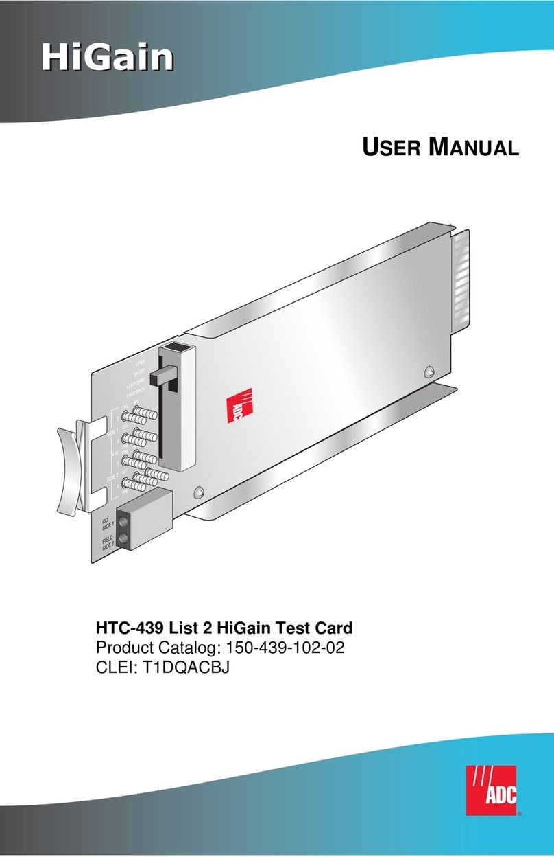
LOOPBACK TESTING
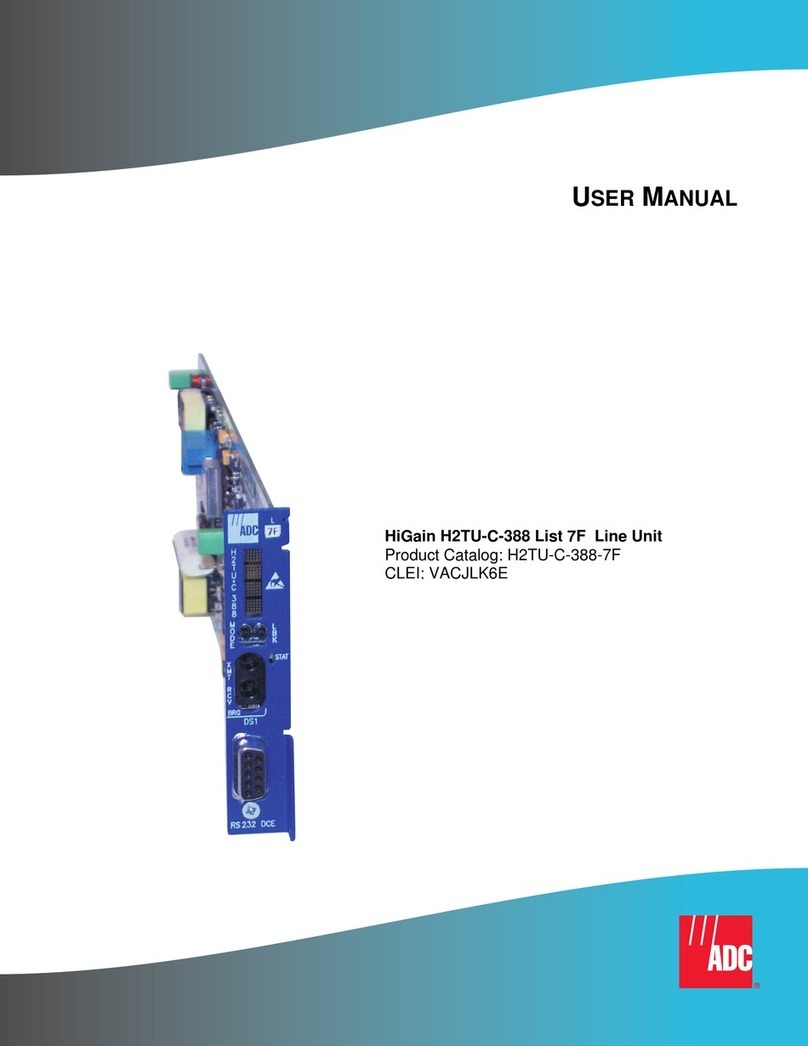
Initiate loopback testing from the HiGain maintenance menus. The inband codes shown
below can be sent by a test set.
Craft Port Configuration Options
CONFIGURATION SWITCH DESCRIPTION
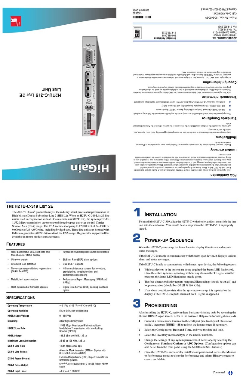
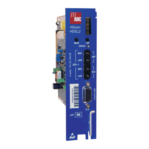
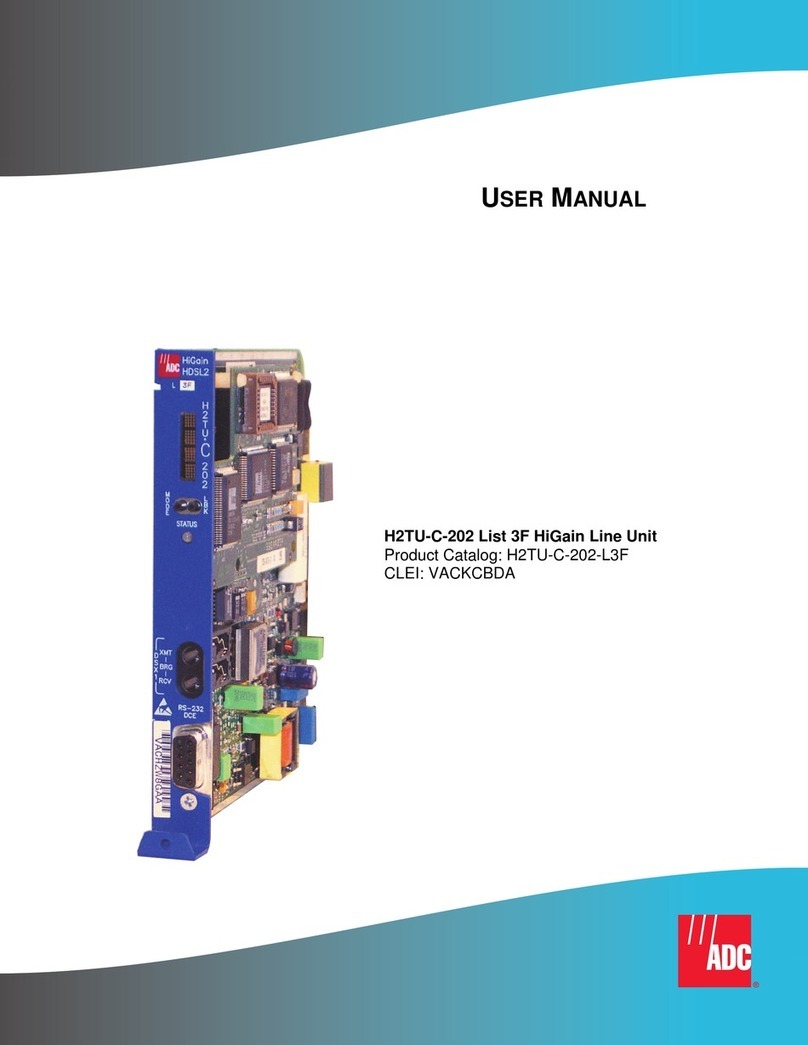
The H2TU-C-202 has a dip switch bank containing eight switches (located on the board).
The switches are shown in the figure below and are described in detail in the Switch
Descriptions table below.
For more detailed information about the HiGain HDSL2 screens, provisioning, and
loopback testing, refer to the H2TU-C-202 List 1E user manual, catalog number
152-202-115-xx. It can be downloaded from the ADC Web site at www.adc.com.
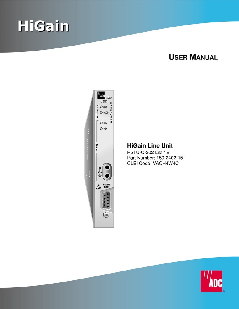
Card handle
List number
Status LEDs
Report the following conditions:
DSX-1 test access jacks
Connect standard test equipment.
Craft port provisioning
To access all system maintenance, provisioning,
and performance screens, connect a standard
9-pin terminal cable between the serial port on a PC
and the H2TU-C craft port.
BRG Provides non-intrusive bridging jack
access to (IN) and from (OUT) the
HDSL2 span at the DSX-1 interface.
Allows monitoring of the T1 payloads.
MaintenanceTerminal Modem Settings
9600 baud
8 data bits
No parity
1 stop bit
Hardware flow control:OFF
Terminal emulation software:VT-100
HiGain
IN
l
BRG
l
OUT
H
2
T
U
*
C
2
0
2
H
D
S
L
2
RS-232
DCE
*
H2TU-C-202 does not have a display
or MODE and SEL buttons.To provision
the , set the board dip
or access the maintenance
terminal menus through the craft port.
H2TU-C-202
switches
(Configuration number
and CLEI code label on
outside of handle)
L
ALM
LOOP
LBK
DSX
D
S
1
ALM LED:
LOOP LED:
LBK LED:
-Solid red when a fuse alarm is present.
-Flashes red once per second while a
local alarm is present.
-Flashes red five times per second while a remote
alarm is present.
-Off when no alarm is present.
-Solid green while all HDSL2 spans are up.
-Flashes green once per second during
a loop acquisition on the span.
-Flashes green five times per second when a
margin or loop attenuation threshold is exceeded.
-Solid yellow when the system is in loopback, NLOC,
or CREM mode.
-Flashes yellow five times a second when the
system is armed.
-Off when the system is not armed or in loopback
mode.
DSX LED:
-Solid green when DSX-1 signal is present and no
alarm is present.
-Flashes green once per second for BPV, FERR,
UAS, or CRC DSX-1 error.
-Flashes green five times per second when network
side framing or line code provisioning does
not match the DSX-1 signal being received.
-Off when the DSX-1 signal is not present.
1E
Dip Switch (located on the board) *Card-edge Connector
DSX-1 EQL Equalization
(switches 1-4)
AMI/B8ZS Line code
(switch 5)
LBTO Loopback timeout
(switch 6)
FT1 Fractional T1
(switch 7)
LCL/SPAN Local/Span Powering
(switch 8)
27
25
23
21
19
17
15
13
11
9
7
3
5
1
DS1 Ring1
DS1 Tip1
Managementbus
Factory use only
Factory use only
HDSL2 Ring
Circuit ground
(-)
(+)
DS1 Ring
DSX-1In
DS1 Tip
HDSL2 Tip
Chassis ground*
Fusealarm
28
26
24
22
20
18
16
14
12
10
8
4
6
2
55
53
51
49
47
45
43
41
39
37
35
32 31
56
54
52
50
48
46
44
42
40
38
36
34
30
33
29
Note: Active pins are highlighted in black.
*Chassis ground may be tied to earth ground per local practice.
DSX-1Out
HDSL2
Span
-48Vdc Local Power
Chassis ground*
Alarm
A3LB Loopback Commands
Loopback Inband Code Description
NLOC 1111-1111-0001-1
110 (FF1E) DSX-1 signal is looped back to the network at the H2TU-C.
NRG1 (a)
(a) Regenerators (doublers) are supported in firmware version 3.0 and higher.
1111-1111-0000-0
100 (FF04) DSX-1 signal is looped back to the network at H2RU1.
NRG2 (a) 1111-1111-0000-0
110 (FF06) DSX-1 signal is looped back to the network at H2RU2.
NREM 1111-1111-0000-0
010 (FF02) DSX-1 signal is looped back to the network at the H2TU-R.
SMJK 1111-1111-0100-1
000 (FF48)
100000
11000
DSX-1 signal is looped back to the network at the H2TU-R
SmartJack module. (Choose any one of the three commands.)
CREM 0011-1111-0001-1
110 (3F1E) Signal from customer is looped back to the customer at the
H2TU-C.
CRG1 (a) 0011-1111-0000-0
100 (3F04) Signal from customer is looped back to the customer at H2RU1.
CRG2 (a) 0011-1111-0000-0
110 (3F06) Signal from customer is looped back to the customer at H2RU2.
CLOC 0011-1111-0000-0
010 (3F02) Signal from customer is looped back to the customer at the
H2TU-R.
Loopdown 1111-1111-0010-0
100 (FF24)
11100
100
Deactivates any of the above loopbacks. (Choose any one of the
three commands.)
NLOC 1111-1111-0001-1
110 (FF1E) DSX-1 signal is looped back to the network at the H2TU-C.
Display Code Description (default values in bold)
RLBO Sets the H2TU-R line buildout to 0 dB, -7.5 dB, or -15 dB.
LPBK Enables (ENA) or disables (DIS) SmartJack loopback commands.
SPLB xxxx Configures system for generic (GNLB) or special inband loopback commands (A1LB, A2LB, A3LB,
A4LB, A5LB).
SPLB xxxx Configures system for generic (GNLB) or special inband loopback commands (A1LB, A2LB, A3LB,
A4LB, A5LB).
HBER 1E-6 or 1E-7 = alarm activates when the HDSL2 BER alarm threshold exceeds 10-6 or 10-7.
NONE = prevents generation of a system alarm due to BER.
DBER Enables (ENA) or disables (DIS) fixed 24-hour DSX-1 BER alarm threshold.
ALM Enables (ENA) or disables (DIS) alarm indications on pin H.
FRMG DS1 frame formatting = AUTO (auto framing mode) or UNFR (unframed mode).
ALMP Enables system to output an alarm pattern: AIS or LOS.
BPVT Enables (ENA) or disables (DIS) Bipolar Violation Transparency.
NLBP Enables the H2TU-R to transmit either AIS or LOS towards CI for any network loopback.
TLOS Enables (ENA) or disables (DIS) a logic loopback at the H2TU-R when an LOS occurs at its
DS1 input.
RTPV Enables (ENA) or disables (DIS) remote provisioning.
PRM OFF = No enhanced Performance Report Messaging; SPRM = Supplemental PRM; NPRM =
Network PRM; S+N = SPRM + NPRM.
NAIS If ALMP is set to AIS, this option specifies which pattern is sent to the network when a
remote LOS or AIS occurs.
Network Customer
Premises
H2TU-C H2RU1 H2RU2 H2TU-R
NLOC
FF1E NRG1
FF04 NRG2
FF06 CLOC
3F02
CRG1
3F04 CRG2
3F06
CREM
3F1E
SMJK
11000
NREM
FF02
Switch Descriptions (default values in bold)
Left Side Options Switch
Number Right Side Options
Set the equalizer to 133 to 265 feet 1 (a)
(a) Only one of the DSX-1 line equalization switches (1 - 4) can be selected at a time. If more than one switch
is enabled, the lowest value setting has priority.
0
Set the equalizer to 266 to 398 feet 2 (a) 0
Set the equalizer to 399 to 532 feet 3(a) 0
Set the equalizer to 533 to 655 feet 4 (a) 0
Selects the DSX-1 line code Alternate Mark
Inversion (AMI) 5Selects Bipolar with 8-zero Substitution
(B8ZS)
Enables the Loopback Timeout (LBTO) to
120 minutes 6Disables LBTO to NONE
Enables Fractional T1 (FT1) loopback
capability 7Disables FT1 loopback capability
Configures the system for local powering 8Configures the system for Span powering
